EP0846995B1 - Appareil à commande liquide - Google Patents
Appareil à commande liquide Download PDFInfo
- Publication number
- EP0846995B1 EP0846995B1 EP19970121144 EP97121144A EP0846995B1 EP 0846995 B1 EP0846995 B1 EP 0846995B1 EP 19970121144 EP19970121144 EP 19970121144 EP 97121144 A EP97121144 A EP 97121144A EP 0846995 B1 EP0846995 B1 EP 0846995B1
- Authority
- EP
- European Patent Office
- Prior art keywords
- extension
- regulator
- gatelike
- controller
- control apparatus
- Prior art date
- Legal status (The legal status is an assumption and is not a legal conclusion. Google has not performed a legal analysis and makes no representation as to the accuracy of the status listed.)
- Expired - Lifetime
Links
Images


Classifications
-
- F—MECHANICAL ENGINEERING; LIGHTING; HEATING; WEAPONS; BLASTING
- F16—ENGINEERING ELEMENTS AND UNITS; GENERAL MEASURES FOR PRODUCING AND MAINTAINING EFFECTIVE FUNCTIONING OF MACHINES OR INSTALLATIONS; THERMAL INSULATION IN GENERAL
- F16K—VALVES; TAPS; COCKS; ACTUATING-FLOATS; DEVICES FOR VENTING OR AERATING
- F16K27/00—Construction of housing; Use of materials therefor
-
- G—PHYSICS
- G05—CONTROLLING; REGULATING
- G05D—SYSTEMS FOR CONTROLLING OR REGULATING NON-ELECTRIC VARIABLES
- G05D7/00—Control of flow
- G05D7/06—Control of flow characterised by the use of electric means
- G05D7/0617—Control of flow characterised by the use of electric means specially adapted for fluid materials
- G05D7/0629—Control of flow characterised by the use of electric means specially adapted for fluid materials characterised by the type of regulator means
- G05D7/0635—Control of flow characterised by the use of electric means specially adapted for fluid materials characterised by the type of regulator means by action on throttling means
-
- H—ELECTRICITY
- H10—SEMICONDUCTOR DEVICES; ELECTRIC SOLID-STATE DEVICES NOT OTHERWISE PROVIDED FOR
- H10P—GENERIC PROCESSES OR APPARATUS FOR THE MANUFACTURE OR TREATMENT OF DEVICES COVERED BY CLASS H10
- H10P72/00—Handling or holding of wafers, substrates or devices during manufacture or treatment thereof
-
- H—ELECTRICITY
- H10—SEMICONDUCTOR DEVICES; ELECTRIC SOLID-STATE DEVICES NOT OTHERWISE PROVIDED FOR
- H10P—GENERIC PROCESSES OR APPARATUS FOR THE MANUFACTURE OR TREATMENT OF DEVICES COVERED BY CLASS H10
- H10P95/00—Generic processes or apparatus for manufacture or treatments not covered by the other groups of this subclass
-
- F—MECHANICAL ENGINEERING; LIGHTING; HEATING; WEAPONS; BLASTING
- F16—ENGINEERING ELEMENTS AND UNITS; GENERAL MEASURES FOR PRODUCING AND MAINTAINING EFFECTIVE FUNCTIONING OF MACHINES OR INSTALLATIONS; THERMAL INSULATION IN GENERAL
- F16K—VALVES; TAPS; COCKS; ACTUATING-FLOATS; DEVICES FOR VENTING OR AERATING
- F16K51/00—Other details not peculiar to particular types of valves or cut-off apparatus
-
- Y—GENERAL TAGGING OF NEW TECHNOLOGICAL DEVELOPMENTS; GENERAL TAGGING OF CROSS-SECTIONAL TECHNOLOGIES SPANNING OVER SEVERAL SECTIONS OF THE IPC; TECHNICAL SUBJECTS COVERED BY FORMER USPC CROSS-REFERENCE ART COLLECTIONS [XRACs] AND DIGESTS
- Y10—TECHNICAL SUBJECTS COVERED BY FORMER USPC
- Y10T—TECHNICAL SUBJECTS COVERED BY FORMER US CLASSIFICATION
- Y10T137/00—Fluid handling
- Y10T137/8593—Systems
- Y10T137/877—With flow control means for branched passages
- Y10T137/87885—Sectional block structure
Definitions
- Fluid control apparatus comprise a regulator for regulating the rate of flow or pressure, a regulator extension provided on each of the front and rear sides of lower end of the regulator, and a connecting member butted against the bottom face of the extension, the extension being removably connected to the connecting member with a seal portion interposed therebetween so that an inverted L-shaped channel formed in the extension and having an opening in its bottom face communicates with an L-shaped channel formed in the connecting member and having an opening in its upper surface (see JP-A-241400/1994).
- the fluid control apparatus of the type described it is necessary to frequently perform the procedure of removing the regulator and installing the regulator again for the maintenance and inspection of the regulator. Accordingly, it is desired to mount the fluid control apparatus on an aluminum panel so as to render the regulator singly removable upward.
- the regulator is attached to the connecting member by inserting two bolts through the regulator extension and screwing the bolts into respective threaded bores in the connecting member.
- the two bolts are positioned symmetrically on opposite sides of the seal portion.
- the apparatus has the problem that this procedure is cumbersome and difficult.
- the panel for mounting the apparatus thereon is vertical, difficulty is experienced in screwing the bolts into the respective threaded bores in the connecting member, so that the apparatus also has the problem of causing damage to the seal portion by this procedure to result in impaired fluid tightness, and the problem of allowing the bolt to fall off and become lost in removing the regulator.
- the flow rate is controlled on the premise that the fluid flowing into the controller is in the form of a laminar flow, whereas turbulence will occur because the fluid passes through the inverted L-shaped channel and the L-shaped channel before flowing into the massflow controller. This entails the problem of impairing the flow rate control accuracy of the controller.
- An object of the invention is to provide a fluid control apparatus comprising a regulator which is easy to install and remove.
- the terms upper and lower as used herein refer respectively to the upper and lower sides of FIG. 1. Further the right-hand side and the left-hand side of the drawing are referred to as front and rear, respectively. The terms upper and lower are used for the sake of convenience; the apparatus may be used as turned upside down or with its upper side positioned laterally.
- the term regulator refers to a massflow controller, pressure regulator or like device for regulating a flow rate or pressure.
- the term connecting member refers to a monofunctional member which is to be connected to the regulator, such as an on-off valve, regulating valve, check valve, filter or block formed with a fluid channel.
- the pressing member presses the regulator extension against the connecting member from immediately above the seal portion, so that there is no need to consider the fastening balance unlike the case wherein two bolts symmetrically positioned with respect to the seal portion are tightened.
- the regulator is therefore easy to install.
- the pressing member comprises, for example, a male screw portion screwed in a female screw portion extending through a top wall of the gatelike member, a spanner engaging head integral with an upper end of the male screw portion, and a projection in the form of a short cylinder integral with a lower end of the male screw portion. Since only one pressing member is disposed above the seal portion in this case, the male screw portion can be given a greater thickness than in the conventional arrangement wherein two bolts are positioned symmetrically on opposite sides of the seal portion, with the result that the male screw can be given a greater thread pitch. This assures proper tightening by controlling not only the torque but also the number of turns.
- the pressing member may comprise a female screw element in the form of a bottomed tube and having a lower end face movable into contact with an upper surface of the extension, and a male screw element screwed in the female screw element, the male screw element comprising a shank upwardly and downwardly movably inserted through a bore extending through a top wall of the gatelike member, and a spanner engaging head provided at an upper end of the shank and having a bottom face bearing on an upper surface of the top wall of the gatelike member.
- the male screw element moves the female screw element upward when screwed into the female screw element or moves the female screw element down when unscrewed from this element. Further since the female screw element merely moves upward or downward without rotation at this time, the female screw element is thus movable free of the influence of the friction between the lower end face of the female screw element and the upper surface of extension of the controller, hence a stabilized tightening torque value.
- the connecting member has a through bore extending transversely therethrough, and a rod rotatably inserted through the bore has opposite ends fixed to respective lower ends of the side walls of the gatelike member, the gatelike member being pivotally movable to a position where the gatelike member permits removal and installation of the regulator free of interference therewith.
- the gatelike member can then be pivotally moved so as not to interfere with the regulator to be removed, while the gatelike member is prevented from slipping off from the connecting member.
- the regulator is therefore removable with ease.
- the connecting member has a guide groove extending therethrough transversely of the apparatus and extending longitudinally thereof, and a rod fitted in the guide groove and movable forward and rearward has opposite ends fixed to respective lower ends of the side walls of the gatelike member, the gatelike member being movable forward or rearward to a position where the gatelike member permits removal and installation of the regulator free of interference therewith.
- the gatelike member is then moved forward or rearward so as not to interfere with the regulator to be removed. In removing the regulator, moreover, the gatelike member is prevented from slipping off from the connecting member. This assures facilitated removal of the regulator.
- the regulator is formed with positioning pin fitting grooves extending vertically. Positioning pins are provided upright on the panel for mounting the regulator thereon, and are fitted into the respective grooves. This restrains the regulator from moving forward, rearward or transversely of the apparatus, consequently precluding displacement of the seal portion and uneven tightening. In the case where the regulator is to be attached to a vertical panel, the regulator can be prevented from falling off under gravity and can therefore be installed with greater ease.
- the bottom face of the extension is inclined upward toward a direction away from the regulator, and the connecting member has an inclined face in conformity with and butted against the inclined bottom face.
- the connecting member has an inclined face in conformity with and butted against the inclined bottom face.
- the regulator is a massflow controller
- a channel formed in the extension and a channel formed in the connecting member preferably have an obtuse angle of intersection at the butting faces.
- the fluid flowing into the massflow controller is then likely to become a laminar flow, with the result that the controller which is designed to control the rate of a laminar flow provides accurate flow rate control without impairment.
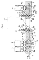
- FIG. 1 shows a first embodiment of fluid control apparatus for use in semiconductor manufacturing equipment.
- the embodiment comprises a first fluid inlet portion 1, first on-off valve 2, second on-off valve 3, channel block 4, massflow controller (regulator) 5, third on-off valve 6 and fluid outlet portion 7 which are arranged in this order from the rear forward.
- a second fluid inlet portion 8 is provided under the second on-off valve 3.
- the members 1, 2, 3, 4, 5, 6, 7 adjacent to one another longitudinally of the apparatus, as well as the second on-off valve 3 and the second fluid inlet portion 8, are joined to one another with a seal portion 18 of common construction (not shown in detail) interposed therebetween.
- a rearward extension 9 in the form of a block is provided at the rear side of lower end portion of the massflow controller 5.
- a forward extension 10 in the form of a block is provided at the front side of lower end portion of the controller 5.
- the rearward extension 9 of the controller 5 is removably attached to the front end of the channel block 4 by a fastener 11.
- the forward extension 10 of the controller 5 is attached to the rear end of main body 16 of the third on-off valve 6 in the same manner.
- Each of the fasteners 11 comprises a rotatable rod 20 rotatably inserted through a bore 19 extending through the front end of the channel block 4 or the rear end of main body 16 of the third on-off valve 6 transversely of the apparatus, a gatelike member 21 mounted on the rotatable rod 20, and a pressing member 22 for pressing the extension 9 or 10 of the massflow controller 5 from above the seal portion 18 against the block 4 or the third on-off valve main body 16 as will be described later in greater detail.
- the rearward extension 9 has a bottom face 9a in the form of a slope inclined forwardly downward at an angle of about 45 deg.
- the extension 9 has an inflow channel 42 communicating with a channel 43 in the main body of the massflow controller 5 for passing a fluid therethrough from the rear forward.
- the inflow channel 42 has an inclination smaller than a right angle with respect to the bottom face 9a of the extension 9. Consequently, the inflow channel 42 forms an obtuse angle of about 150 deg with the channel 43 in the main body of the massflow controller.
- the forward extension 10 has a bottom face 10a in the form of a slope inclined forwardly upward at an angle of about 45 deg.
- the extension 10 has an outflow channel 44 communicating with the channel 43 in the massflow controller 5.
- the outflow channel 44 extends in a direction approximately perpendicular to the bottom face 10a of the extension 10. Consequently, the outflow channel 44 forms an obtuse angle of about 135 deg with the controller main body channel 43.
- the channel block 4 provided between the second on-off valve 3 and the massflow controller 5 is formed with the communication channel 41 for causing the outflow channel 40 in the main body 3a of the second on-off valve 3 to communicate with the inflow channel 42 of the rearward extension 9 of the controller 5.
- the block 4 has a front-end upper face 4a butting against the controller rearward extension 9 and in the form of a slope inclined forwardly downward in conformity with the forwardly downward bottom face 9a of the extension 9.
- the communication channel 41 of the channel block 4 comprises an upstream portion 41a communicating with an outflow channel 40 of the second on-off valve 3, and a downstream portion 41b communicating with the inflow channel 42 of the controller 5.
- the upstream portion 41a is slightly inclined forwardly downward
- the downstream portion 41b is slightly inclined forwardly upward
- these portions 41a and 41b make an obtuse angle of about 150 deg.
- the downstream portion 41b has an inclination smaller than a right angle with respect to the front-end upper face 4a of the block 4. Consequently, the downstream portion 41b makes an obtuse angle of about 165 deg with the inflow channel 42 of the controller 5.
- the length of main body 3a of the second on-off valve 3 is equal to that of the main body 2a of the first one-off valve.
- the main body 16 of the third on-off valve 6 has approximately twice the length of the main body 2a of the first on-off valve 2.
- the third on-off vale 6 has an actuator portion 6a which is provided in the front half of the valve main body 16.
- the main body 16 of the third on-off valve 6 has a rear-end upper face 16a butting against the forward extension 10 of the controller 5 and in the form of a slope which is inclined forwardly upward at the same angle as the forwardly upward bottom face 10a of forward extension 10 of the controller 5, i.e., about 45 deg.
- the third on-off valve 6 has an inflow channel 45 which comprises an upstream portion 45a extending forwardly downward from the front end of outflow channel 44 of the controller forward extension 10, and a downstream portion 45b extending vertically upward from the front end of the upstream portion 45a.
- the upstream portion 45a has a smaller inclination than a right angle with respect to the rear-end upper face 16a of the third on-off valve main body 16. Consequently, the inflow channel upstream portion 45a of the main body 16 makes an obtuse angle of about 150 deg with the outflow channel 44 of the controller 5.
- the upstream portion 45a further forms an acute angle of about 75 deg with the downstream portion 45b.
- the fluid flowing out from the outflow channel 40 of the second on-off valve 3 flows through the communication channel upstream portion 41a of the channel block 4, the downstream portion 41b making an obtuse angle with the portion 41a and the inflow channel 42 of the controller rearward extension 9 making an obtuse angle with the portion 41b, enters the channel 43 of the controller main body making an obtuse angle with the channel 42, and further flows through the forward extension outflow channel 44 making an obtuse angle with the channel 43 into the inflow channel upstream portion 45a of the third on-off valve 6 making an obtuse angle with the channel 44.
- the channels 41a, 41b, 42, 43, 44, 45a in front and rear of the massflow controller 5 all make an obtuse angle with one another. This assures that the fluid through the channel 43 in the controller main body will be in the form of a laminar flow. This obviates the problem of the conventional fluid control apparatus that the passage through the inverted L-shaped channel and L-shaped channel before entering the massflow controller produces turbulence to impair the flow control accuracy of the controller.
- FIG. 3 is a view in section taken along the line III-III of FIG. 2, which is an enlarged view of FIG. 1.
- the left- and right-hand sides of FIG. 3 correspond respectively to the terms left and right as used herein.
- Each side wall 21a is formed with a hole 30 in its lower end.
- the rotatable rod 20 has its opposite ends fixedly fitted in the respective holes 30, whereby the gatelike member 21 is made pivotally movable about the axis of the rod 20 extending transversely of the apparatus, and the fastener 11 is prevented from falling off.
- This structure for making the member 21 pivotally movable and preventing the fastener 11 from falling off is not limitative; the rod 20 may be replaced by opposed flanged pins loosely inserted through the respective holes 30 of the side walls 21a from outside having their inner ends inserted into a through bore 19 19 of the channel block 4 by a press fit.
- the pressing member 22 comprises the above-mentioned elements, i.e., the female screw element 24 in the form of a tube having a bottom, and the male screw element 23 screwed in the element 24.
- the female screw element 24 which is a tube having an approximately circular cross section, is internally threaded and formed on its outer periphery with a pair of left and right flat faces 24a parallel to each other. The distance between the flat faces 24a is made approximately equal to the left-to-right width of the female element guide recess 29 formed in the bottom of top wall 21b of the gatelike member 21.
- the female screw element 24 has an upper end portion fitted in the recess 29 slidably and nonrotatably, and a lower end face which is movable into or out of contact with the upper surface of extension 9 or 10 of the massflow controller 5 with the rotation of the male screw element 23.
- the extension 9 or 10 is formed in its upper surface with a cavity 39 circular-arc in vertical section and extending transversely of the apparatus for receiving the lower end face, circular-arc in vertical section, of the female screw element 24 to position the pressing member 22 in place when the controller 5 is installed.
- the male screw element 23 comprises a shank 25 inserted through the bore 28 of the gatelike member top wall 21b and movable upward or downward, a spanner engaging head 26 provided at the upper end of the shank 25 and having a lower face bearing on the upper surface of the top wall 21b, and an externally threaded portion 27 extending from the lower end of the shank 25 and having a slightly greater diameter than the shank 25.
- the head 26 has a regular hexagonal cross section and a socket 26a facing downward and having fitted therein the upper end of the shank 25 projecting upward beyond the top wall 21b.
- the shank 25 is connected to the head 26 by a spring pin 31.
- the head 26 may be square in cross section, or may have a circular cross section and a spanner engaging socket in its top.
- the male screw element 23 moves the female screw element 24 upward when screwed into the female screw element 24 or moves the element 24 down when unscrewed from the element 24. Since the female screw element 24 merely moves upward or downward without rotation at this time, the element 24 is thus movable free of the influence of the friction between the lower end face of the element 24 and the upper surface of extension 9 or 10 of the controller 5, hence a stabilized tightening torque value.
- the male and female screw elements 23 and 24 may be right-handed or left-handed, whereas when the element 24 is to be pressed against the extension by rotating the male screw element 23 rightward, both the screw elements 23, 24 are left-handed.
- the massflow controller 5 is removable upward by moving the female screw element 24 in the state shown in FIGS. 1 to 3 upward and then turning the element away from the controller 5.
- the controller extension 9 and the channel block 4 have their left and right sides held between the lower portions of the side walls 21a and are thereby positioned in place transversely of the apparatus, so that even if the panel on which the apparatus is to be installed is vertical, the apparatus can be installed efficiently without necessitating much time for positioning or effecting screw-thread engagement. This obviates problems such as causing damage to the seal portions during the installation procedure to result in impaired fluid tightness.
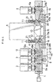
- FIG. 4 shows a second embodiment of fluid control apparatus for use in semiconductor manufacturing equipment.
- the embodiment comprises a first fluid inlet portion 1, first on-off valve 2, second on-off valve 3, fourth on-off valve 12, massflow controller 5, third on-off valve 6 and fluid outlet portion 7 which are arranged in this order from the rear forward.
- a second fluid inlet portion 8 is provided under the second on-off valve 3.
- Channel blocks 13, 14 are provided under the fourth on-off valve 12 and the third on-off valve 6, respectively, and interconnected by a tube 15.
- the first fluid inlet portion 1, first on-off valve 2, second on-off valve 3, massflow controller 5 and fluid outlet portion 7 are the same as those in the first embodiment.
- the main body 16 of the third on-off valve 6 is additionally provided with a channel communicating with the channel block 14.
- the fourth on-off valve 12 has a main body 17 in the form of a block.
- the main body 17 has approximately twice the length of the main body 2a of the first on-off valve 2.
- the valve 12 has an actuator portion 12a which is provided on the rear half of the valve main body 17.
- the valve main body 17 has a front-end upper face 17a which is in the form of a slope inclined forwardly downward at the same angle as the bottom face 9a of rearward extension 9 of the controller 5, i.e., about 45 deg.
- the upper face 17a is butted against the bottom face 9a of the extension 9.
- the fourth on-off valve 12 has an outflow channel 48, which comprises a downwardly extending upstream portion 48a, and a downstream portion 48b communicating with the inflow channel 42 of the controller 5.
- the upstream portion 48a makes an acute angle of about 75 deg with the downstream portion 48b which is slightly inclined forwardly upward.
- the downstream portion 48b has an inclination smaller than a right angle with respect to the front-end upper face 17a of the valve main body 17. Consequently, the outflow channel downstream portion 48b of the fourth on-off valve forms an obtuse angle of about 165 deg with the inflow channel 42 of the massflow controller 5.
- the channel block 4 of the first embodiment is replaced by the fourth on-off valve 12.
- like parts are designated by like reference numerals or symbols and will not be described repeatedly.
- the massflow controller 5 is connected to the channel block 4 or the valve main body 17, and to the valve main body 16, whereas the controller 5 may be replaced by a regulator such as a pressure regulator or one of various valves for regulating the rate of low or pressure.
- a filter or other member may be connected to such a regulator or valve in a suitable combination to provide a fluid control apparatus.
- the bottom faces 9a, 10a of the extensions 9, 10 and the butt faces 4a, 16a, 17a of the block 4 and the valve main bodies 16, 17 are slopes according to the foregoing embodiments, whereas the fasteners 11 are usable even if these butt faces 9a, 10a, 4a, 16a, 17a are not slopes. While the channels 41a, 41b, 42, 43, 44, 45a, 48b in front and rear of the massflow controller 5 make an obtuse angle with one another, this arrangement is usable even if the butt faces 9a, 10a, 4a, 16a, 17a are not inclined.
- the third embodiment of fluid control apparatus comprises a massflow controller 5, and first and second on-off valves 33, 34 arranged respectively at the rear side and the front side of the controller.
- the controller 5 differs from those of the foregoing embodiments in that it is formed in each of its left and right sides with a vertical pin fitting groove 35 extending to the lower end of the controller. Accordingly, the same reference numerals as in the foregoing embodiments are used for the controller 5 to avoid repeated description.
- the first on-off valve 33 has a blocklike forward extension 36 at the front side of its main body.
- the second on-off valve 34 has a blocklike rearward extension 37 at the rear side of its main body.
- the forward extension 36 of the first on-off valve 33 is formed with an outflow channel 64 communicating with the controller 5 and comprising a horizontal upstream portion 64a, and a downstream portion 64b orthogonal to the slanting face 37c.
- the upstream portion 64a makes an obtuse angle of about 145 deg with the downstream portion 64b.
- the angle between the downstream portion 64b and the inflow channel 42 of the controller 5 is 180 deg.
- the rearward extension 9 of the controller 5 is removably attached to the forward extension 36 of the first on-off valve 33 by a fastener 38.
- the forward extension 10 of the controller 5 is similarly attached to the rearward extension 37 of the second on-off valve 34.
- Each of the fasteners 38 comprises gatelike member 51 including left and right side walls 51a opposed to each other as spaced apart by a distance equal to the left-to-right width of the extension 36 or 37 of the valve 33 or 34, and a top wall 51b formed with a female screw portion 54 extending therethrough; a horizontal rod 52 connected between the lower ends of the member 51; and a pressing member 53 extending through the female screw portion 54 of the gatelike member 51 in screw-thread engagement therewith for pressing the extension 9 or 10 against the valve extension 36 or 37.
- the pressing member 53 comprises a male screw portion 55 screwed in the female screw portion 54 of the gatelike member 51, a spanner engaging head 56 integral with the upper end of the portion 55, and a projection 57 integral with the lower end of the male screw portion 55, in the form of a short cylinder and having a lower end face with a circular-arc vertical section.
- the rearward or forward extension 9 or 10 of the massflow controller 5 is formed in its upper surface with the cavity 39 circular-arc in vertical section and extending transversely of the apparatus for receiving the lower end face of the projection 57 of the pressing member 53 to position the pressing member in place when the controller 5 is installed.
- the upper surfaces 36b, 37b of extensions 36, 37 of the on-off valves 33, 34 are also each formed with a cavity 49 shaped similarly for positioning the pressing member 53 in place when the controller 5 is to be removed.
- the lower surfaces 36a, 37a of extensions 36, 37 of the on-off valves 33, 34 are each formed with a guide groove 58 for guiding the horizontal rod 52 of the fastener 38.
- the guide groove 58 is open downward, and the bottom face of the grooved portion 58 is formed at its front and rear end with respective cavities 59, 60 circular-arc in vertical section and extending transversely of the apparatus for the horizontal rod 52 to engage in to position the rod 52 in place when the controller is installed and when it is to be removed.
- the rod positioning cavity 59 for the installation of the controller is positioned below the pressing member positioning cavity 39 for the installation of the controller.
- the rod positioning cavity 60 for the removale of the controller is positioned below the pressing member positioning cavity 49 of extension 36 or 37 of the valve 33 or 34 for the removal of the controller.
- the center of the cavity 39 and the center of the cavity 59 are arranged on a vertical line above and below the center of the seal portion 18, respectively.
- a panel 61 for mounting the massflow controller 5 and the on-off valves 33, 34 thereon is provided with a pair of left and right vertical guide pins 62 fittable in the respective pin fitting grooves 35 in the controller 5.
- the first and second on-off valves 33, 34 are first fastened to the panel 61 from above.
- the horizontal rod 52 of each fastener 38 wherein the male screw portion 55 is unscrewed is fitted into the guide groove 58 of each of the extensions 36, 37 of the valves 33, 34, the projection 57 of the pressing member 53 is positioned above the cavity 49, and the rod 52 is fitted to the cavity 60.
- the male screw portion 55 of the pressing member 53 is tightened in this state, whereby the fastener 38 is temporarily held in a position where the fastener will not interfere with the massflow controller 5 to be mounted as indicated in broken lines in FIG. 6.
- the guide pins 62 are then fitted into the grooves 35 in the controller 5, whereby the bottom face 9a of rearward extension 9 of the controller 9 is butted against the slanting face 36c of forward extension 36 of the first valve 33, and the bottom face 10a of forward extension of the controller 5 against the slanting face 37c of rearward extension 37 of the second valve 34.
- the male screw portion 55 of each pressing member 53 is subsequently loosened, the horizontal rod 52 is moved toward the controller 5 along the guide groove 58, the projection 57 of the pressing member 53 is positioned above the recess 39, and the rod 52 is fitted into the cavity 59.
- the male screw portion 55 of each pressing member 53 is then progressively screwed in, the projection 57 of the pressing member 53 fits into the cavity 39.
- the controller 5 is connected to the first and second on-off valves 33, 34.
- the rod positioning cavity 59 for the installation of the controller and the pressing member positioning cavity 39 for the installation of the controller determine the position of the fastener 38, whereby the extension 9 (10) of the controller 5 is pressed against the extension 36 (37) of the valve 33 (34).
- the controller 5 is positioned in place for installation by fitting the guide pins 62 into the grooves 35 of the controller 5, and also by the side walls 51a of each gatelike member 51 holding the controller extension 9 (10) and extension 36 (37) of the valve 33 (34) from opposite sides thereof. Accordingly, the controller 5 is restrained from moving forward, rearward or transversely, so that even if the panel for mounting the apparatus thereon is vertical, the controller can be positioned in place and the bolts can be screwed into the respective threaded bores without necessitating much time, hence an improved work efficiency.
- the above feature also obviates the problem of causing damage to the seal portions by the work to impair the sealing property, and the problem of displacement of the seal portions and uneven tightening.
- the massflow controller 5 can be installed to the panel 61 as positioned vertically, without falling off under gravity. This assures a further facilitated installation procedure.
- the fastener 38 can be held temporarily and is therefore unlikely to pivotally move downward under gravity and to block, for example, the space for the installation of the controller 5, even if the panel 61 is vertical.
- the arrangement described is thus advantageous especially for mounting the controller 5, etc. on the vertical panel 61.
- the fastener 11 of the first and second embodiments and the fastener 38 of the third embodiment are interchangeable.
- the fastener 11 of the first and second embodiments may be incorporated into the third embodiment, while the fastener 38 of the third embodiment is usable in the form of the first or second embodiment.
- the pressing member 53 having the male screw member 23 or the male screw portion 55 is singly disposed above the seal portion 18.
- the male screw portion 27 or 55 can therefore be given a greater thickness than in the conventional arrangement wherein two bolts are positioned symmetrically on opposite sides of the seal portion 18, with the result that the male screw portion 27 or 55 can be given a greater thread pitch. This assures proper tightening by controlling not only the torque but also the number of turns.
Landscapes
- Engineering & Computer Science (AREA)
- Physics & Mathematics (AREA)
- General Physics & Mathematics (AREA)
- Automation & Control Theory (AREA)
- General Engineering & Computer Science (AREA)
- Mechanical Engineering (AREA)
- Valve Housings (AREA)
- Flow Control (AREA)
- Control Of Non-Electrical Variables (AREA)
- Sliding Valves (AREA)
- Pipeline Systems (AREA)
Claims (8)
- Un dispositif de contrôle de fluide comprenant un régulateur (5) pour régler le débit de flux ou la pression, une extension de régulateur (9, 10) pourvu sur chaque côté frontal ou arrière d'une partie terminale inférieure du régulateur (5) et un membre de connexion (4, 16, 17, 16, 36, 37) butés contre une face de fond (9a, 10a) de l'extension du régulateur (9, 10), l'extension de régulateur (9, 10) étant connexion de façon amovible au membre de connexion (4, 16, 17, 16, 36, 37) avec une partie d'étanchéité (18) interposée entre les deux, le dispositif de contrôle de fluide étant caractérisé en ce que le membre en forme d'arche (21, 51) est fixé au membre de connexion (4, 16, 17, 16, 36, 37) de telle sorte à éviter le glissement hors du membre de connexion (4, 16, 17, 16, 36, 37) et en ce qu'il a des parois latérales gauches et droites (21a, 51a) pour maintenir l'extension (9, 10) et le membre de connexion (4, 16, 16, 17, 36, 37) entre eux à partir des côtés opposés gauches et droits; le membre en forme d'arche (21, 51) ayant un membre de pression (22, 53) pour presser l'extension (9, 10) contre le membre de connexion (4, 16, 17, 16, 36, 37) immédiatement au dessus de la partie d'étanchéité (18).
- Un dispositif de contrôle de fluide selon la revendication 1, dans laquelle le membre de connexion (4, 16, 17, 16, 36, 37) a un alésage de passage (19) s'étendant de manière transversale à travers ledit membre et une tige (20) insérée de manière à pouvoir tourner à travers l'alésage (19) ayant des extrémités opposées fixées aux extrémités inférieures respectives des parois latérales (21a) du membre en forme d'arche (21); le membre en forme d'arche (21) pouvant être déplacé de manière à pivoter dans une position où le membre en forme d'arche (21) permet de retirer et d'installer le régulateur (5) sans avoir d'interférence.
- Un dispositif de contrôle de fluide selon la revendication 1, dans lequel le membre de connexion (36, 37) a une rainure de guidage (58) s'étendant au travers de manière transversale par rapport au dispositif et s'étendant de maniéré longitudinale par rapport au dispositif ainsi qu'une tige (52) placée dans la rainure de guidage (58) qui est susceptible de se déplacer vers l'avant et vers l'arrière et a des extrémités opposées fixées aux extrémités inférieures respectives des parois latérales (51) du membre en forme d'arche (51), le membre en forme d'arche étant susceptible de se déplacer vers l'avant et vers l'arrière vers une position dans laquelle le membre en forme d'arche 51 permet un enlèvement et une installation du régulateur (5) sans difficultés.
- Un dispositif de contrôle de fluide selon n'importe laquelle des revendications précédentes, dans lequel le régulateur (5) est formé de rainures de guidage (35) de positionnement de tige s'étendant verticalement.
- Un dispositif de contrôle de fluide selon n'importe laquelle des revendications, dans lequel la face de fond (9a, 10a) de l'extension (9,10) est inclinée vers le haut en direction qui s'éloigne du régulateur (5) et dans lequel le membre de connexion (4, 16, 17, 16, 36, 37) a une face inclinée (4a, 16a, 17a, 36c, 37c) conforme avec et butée contre la face de fond inclinée (9a, 10a).
- Un dispositif de contrôle de flux selon n'importe laquelle des revendications, dans lequel le régulateur est un contrôleur de flux de masse (5) et un canal (42, 44) formé dans l'extension (9, 10) et un canal (41a, 41b, 45a, 48b) formé dans le membre de connexion (4, 16) qui ont un angle obtus à l'intersection des faces de butée (4a, 16a).
- Un dispositif de contrôle de fluide selon la revendication 1, dans lequel le membre de pression (53) comprend une partie de vis (55) mâle vissée dans une partie de vis (54) femelle s'étendant à travers une paroi de plafond (51b) du membre en forme d'arche (51), une tête (56) s'engageant dans une clé et formant une pièce avec une extrémité supérieure de la partie (55) de vis mâle et une saillie (57) sous la forme d'un court cylindre formant une pièce avec une extrémité inférieure à la partie (55) de vis mâle.
- Un dispositif de contrôle de fluide selon la revendication 1, dans lequel le membre de pression (22) comprend un élément de vis (24) femelle sous la forme d'un tube doté d'un fond et ayant une face d'extrémité inférieure susceptible d'être bougée lors d'un contact avec une surface supérieure de l'extension (9, 10) et un élément (23) de vis mâle vissé dans l'élément (24) de vis femelle; l'élément (23) de vis mâle comprenant une tige (25) qui peut être déplacée vers le haut et vers le bas et qui est inséré à travers un alésage (28) s'étendant à travers une paroi de plafond (21b) du membre en forme d'arche (21) et comprenant une tête (26) s'engageant dans une clé pourvue à une extrémité supérieure de la tige (25) et ayant une face de fond s'appuyant sur une surface supérieure de la paroi de plafond du membre en forme d'arche (21).
Applications Claiming Priority (6)
| Application Number | Priority Date | Filing Date | Title |
|---|---|---|---|
| JP322664/96 | 1996-12-03 | ||
| JP32266496 | 1996-12-03 | ||
| JP32266496 | 1996-12-03 | ||
| JP18658097A JPH10220698A (ja) | 1996-12-03 | 1997-07-11 | 流体制御装置 |
| JP18658097 | 1997-07-11 | ||
| JP186580/97 | 1997-07-11 |
Publications (3)
| Publication Number | Publication Date |
|---|---|
| EP0846995A2 EP0846995A2 (fr) | 1998-06-10 |
| EP0846995A3 EP0846995A3 (fr) | 1998-07-08 |
| EP0846995B1 true EP0846995B1 (fr) | 2003-01-15 |
Family
ID=26503854
Family Applications (1)
| Application Number | Title | Priority Date | Filing Date |
|---|---|---|---|
| EP19970121144 Expired - Lifetime EP0846995B1 (fr) | 1996-12-03 | 1997-12-02 | Appareil à commande liquide |
Country Status (6)
| Country | Link |
|---|---|
| US (1) | US5967489A (fr) |
| EP (1) | EP0846995B1 (fr) |
| JP (1) | JPH10220698A (fr) |
| KR (1) | KR19980063650A (fr) |
| DE (1) | DE69718428T2 (fr) |
| TW (1) | TW338091B (fr) |
Cited By (1)
| Publication number | Priority date | Publication date | Assignee | Title |
|---|---|---|---|---|
| USD486501S1 (en) | 2001-10-13 | 2004-02-10 | Swagelok Company | Combined snap assembly actuator housing and mounting bracket |
Families Citing this family (22)
| Publication number | Priority date | Publication date | Assignee | Title |
|---|---|---|---|---|
| JP3921565B2 (ja) * | 1998-07-10 | 2007-05-30 | 株式会社フジキン | 流体制御装置 |
| JP4200245B2 (ja) * | 1998-11-11 | 2008-12-24 | 株式会社フジキン | 流体継手 |
| JP2004526919A (ja) * | 2001-04-26 | 2004-09-02 | スウエイジロク・カンパニー | スナップコネクタを備えた弁 |
| US20030079786A1 (en) * | 2001-10-30 | 2003-05-01 | Diana Michael J. | Modular fluid pressure regulator with bypass |
| JP2005539375A (ja) * | 2002-08-27 | 2005-12-22 | セレリティ・インコーポレイテッド | 共通の平面にマニホルド接続を有するモジュール式基板ガスパネル |
| JP2005121210A (ja) * | 2003-09-26 | 2005-05-12 | Fujita Giken Kogyo Kk | 弁装置の取付構造、取付方法及び弁装置 |
| JP2006234110A (ja) * | 2005-02-25 | 2006-09-07 | Ckd Corp | ガス供給ユニット及びガス供給システム |
| US8403124B2 (en) * | 2005-03-30 | 2013-03-26 | Strattec Security Corporation | Residual magnetic devices and methods |
| JP2007046697A (ja) * | 2005-08-10 | 2007-02-22 | Fujikin Inc | 継手付き流体制御器 |
| JP5096696B2 (ja) * | 2006-03-02 | 2012-12-12 | サーパス工業株式会社 | 流体機器ユニット構造 |
| WO2007141828A1 (fr) | 2006-06-02 | 2007-12-13 | Ckd Corporation | Unité et système d'alimentation en gaz |
| WO2008149702A1 (fr) * | 2007-05-31 | 2008-12-11 | Tokyo Electron Limited | Appareil de régulation de fluide |
| US8307854B1 (en) | 2009-05-14 | 2012-11-13 | Vistadeltek, Inc. | Fluid delivery substrates for building removable standard fluid delivery sticks |
| CN102804335B (zh) | 2009-06-10 | 2015-10-21 | 威斯塔德尔特有限责任公司 | 极限流速和/或高温流体递送基体 |
| US9074686B2 (en) | 2010-12-06 | 2015-07-07 | Microflex Technologies Llc | Ring seal retainer assembly and methods |
| US9454158B2 (en) | 2013-03-15 | 2016-09-27 | Bhushan Somani | Real time diagnostics for flow controller systems and methods |
| JP1528532S (fr) * | 2014-09-30 | 2015-07-13 | ||
| JP1539278S (fr) * | 2015-03-31 | 2015-11-30 | ||
| US10983538B2 (en) | 2017-02-27 | 2021-04-20 | Flow Devices And Systems Inc. | Systems and methods for flow sensor back pressure adjustment for mass flow controller |
| CN113994460B (zh) * | 2019-04-15 | 2025-05-20 | 朗姆研究公司 | 用于气体输送的模块部件系统 |
| JP7214222B2 (ja) * | 2019-11-15 | 2023-01-30 | 株式会社不二工機 | 流路切換弁 |
| IL308720A (en) * | 2023-11-20 | 2025-06-01 | Ham Let Israel Canada Ltd | Mounting arrangement for interconnecting fluid control devices |
Family Cites Families (11)
| Publication number | Priority date | Publication date | Assignee | Title |
|---|---|---|---|---|
| US2640492A (en) * | 1949-11-14 | 1953-06-02 | Stanley J Sawicki | Device for testing fluid pressure lines |
| US3424430A (en) * | 1966-10-31 | 1969-01-28 | Madeleine M Hoelsch | Swingably supported valve |
| US3548651A (en) * | 1968-12-26 | 1970-12-22 | Junnosuke Itoh | Devices for the adjustment of tire pressures |
| US3981482A (en) * | 1973-10-15 | 1976-09-21 | Whitey Research Tool Co. | Fluid system device |
| FR2446939A1 (fr) * | 1979-01-19 | 1980-08-14 | Outillage Air Comprime | Dispositif d'assemblage d'un embout sur une embase de composants modulaires d'installation hydro-pneumatique |
| CH672011A5 (fr) * | 1987-03-27 | 1989-10-13 | Fischer Ag Georg | |
| JP2603160B2 (ja) * | 1990-12-29 | 1997-04-23 | エスエムシー株式会社 | 弁取付装置 |
| DE4111892C2 (de) * | 1991-04-09 | 1995-04-13 | Mannesmann Ag | Ventilbatterie, insbesondere für gasförmige Medien |
| FR2687193B1 (fr) * | 1992-02-10 | 1994-04-29 | Rexroth Sigma | Dispositif distributeur de telecommande hydraulique. |
| US5305788A (en) * | 1992-08-13 | 1994-04-26 | Whitey Co. | Stream selector for process analyzer |
| JP2568365B2 (ja) * | 1993-02-10 | 1997-01-08 | 株式会社東芝 | ガス供給装置 |
-
1997
- 1997-07-11 JP JP18658097A patent/JPH10220698A/ja not_active Withdrawn
- 1997-12-01 TW TW086118034A patent/TW338091B/zh active
- 1997-12-01 KR KR1019970064988A patent/KR19980063650A/ko not_active Ceased
- 1997-12-02 US US08/982,583 patent/US5967489A/en not_active Expired - Lifetime
- 1997-12-02 EP EP19970121144 patent/EP0846995B1/fr not_active Expired - Lifetime
- 1997-12-02 DE DE69718428T patent/DE69718428T2/de not_active Expired - Fee Related
Cited By (1)
| Publication number | Priority date | Publication date | Assignee | Title |
|---|---|---|---|---|
| USD486501S1 (en) | 2001-10-13 | 2004-02-10 | Swagelok Company | Combined snap assembly actuator housing and mounting bracket |
Also Published As
| Publication number | Publication date |
|---|---|
| KR19980063650A (ko) | 1998-10-07 |
| TW338091B (en) | 1998-08-11 |
| EP0846995A3 (fr) | 1998-07-08 |
| DE69718428D1 (de) | 2003-02-20 |
| JPH10220698A (ja) | 1998-08-21 |
| DE69718428T2 (de) | 2003-08-14 |
| US5967489A (en) | 1999-10-19 |
| EP0846995A2 (fr) | 1998-06-10 |
Similar Documents
| Publication | Publication Date | Title |
|---|---|---|
| EP0846995B1 (fr) | Appareil à commande liquide | |
| CA2276552C (fr) | Dispositif de regulation de flux | |
| CA2208765C (fr) | Valve et appareil de controle de liquide integrant cette valve | |
| KR100232549B1 (ko) | 기기설치용 프레임부재에 대한 유체관련기구의 설치기구 | |
| US6546961B2 (en) | Integrated gas control device | |
| US10197183B2 (en) | Valve stem and plug connections and staking tools | |
| EP0971277B1 (fr) | Dispositif de commande du débit d'un fluide | |
| US7270035B2 (en) | Single-wedge wrenches | |
| JP2006009969A (ja) | 集積化ガス制御装置用流路ブロックとその製造方法並びに集積化ガス制御装置 | |
| KR20090031335A (ko) | 조인트부재의 접속구조 | |
| US20020154959A1 (en) | Insert holder for parting and grooving operations | |
| JP4780558B2 (ja) | 流体制御装置用継手およびそれを用いた流体制御装置 | |
| JP2011149554A (ja) | 流体制御装置用継手 | |
| EP1031733B1 (fr) | Actionneur linéaire avec un système de fixation entre un actionneur et un socle | |
| US6056325A (en) | Swivel body for fluid driven torque wrenches | |
| EP0695883A1 (fr) | Dispositif de mise sous tension de vis | |
| JP7065531B2 (ja) | バルブ装置および流体制御装置 | |
| JPH08164475A (ja) | スライドバルブのプレート煉瓦固定機構 | |
| KR100525821B1 (ko) | 밸브 유지보수장치 | |
| CN220508334U (zh) | 双面可拆螺旋板换热器的试压工装 | |
| JPS628430Y2 (fr) | ||
| JPH10132093A (ja) | 弁装置 | |
| EP3015225A1 (fr) | Outil pneumatique | |
| FR3132129B1 (fr) | Boulon comprenant un écrou permettant d’exercer un effort de traction, outil de serrage permettant d’appliquer une précharge au boulon et procédé de serrage du boulon | |
| AU2021258098A1 (en) | Blanking and Testing arrangement |
Legal Events
| Date | Code | Title | Description |
|---|---|---|---|
| PUAI | Public reference made under article 153(3) epc to a published international application that has entered the european phase |
Free format text: ORIGINAL CODE: 0009012 |
|
| PUAL | Search report despatched |
Free format text: ORIGINAL CODE: 0009013 |
|
| AK | Designated contracting states |
Kind code of ref document: A2 Designated state(s): CH DE FR GB IT LI NL |
|
| AX | Request for extension of the european patent |
Free format text: AL;LT;LV;MK;RO;SI |
|
| AK | Designated contracting states |
Kind code of ref document: A3 Designated state(s): AT BE CH DE DK ES FI FR GB GR IE IT LI LU MC NL PT SE |
|
| AX | Request for extension of the european patent |
Free format text: AL;LT;LV;MK;RO;SI |
|
| 17P | Request for examination filed |
Effective date: 19981023 |
|
| AKX | Designation fees paid |
Free format text: CH DE FR GB IT LI NL |
|
| RBV | Designated contracting states (corrected) |
Designated state(s): CH DE FR GB IT LI NL |
|
| 17Q | First examination report despatched |
Effective date: 20000928 |
|
| GRAG | Despatch of communication of intention to grant |
Free format text: ORIGINAL CODE: EPIDOS AGRA |
|
| GRAG | Despatch of communication of intention to grant |
Free format text: ORIGINAL CODE: EPIDOS AGRA |
|
| GRAH | Despatch of communication of intention to grant a patent |
Free format text: ORIGINAL CODE: EPIDOS IGRA |
|
| RAP1 | Party data changed (applicant data changed or rights of an application transferred) |
Owner name: FUJIKIN INCORPORATED |
|
| GRAH | Despatch of communication of intention to grant a patent |
Free format text: ORIGINAL CODE: EPIDOS IGRA |
|
| GRAA | (expected) grant |
Free format text: ORIGINAL CODE: 0009210 |
|
| AK | Designated contracting states |
Kind code of ref document: B1 Designated state(s): CH DE FR GB IT LI NL |
|
| REG | Reference to a national code |
Ref country code: GB Ref legal event code: FG4D Ref country code: CH Ref legal event code: EP |
|
| REF | Corresponds to: |
Ref document number: 69718428 Country of ref document: DE Date of ref document: 20030220 Kind code of ref document: P |
|
| ET | Fr: translation filed | ||
| PGFP | Annual fee paid to national office [announced via postgrant information from national office to epo] |
Ref country code: DE Payment date: 20031103 Year of fee payment: 7 |
|
| PGFP | Annual fee paid to national office [announced via postgrant information from national office to epo] |
Ref country code: GB Payment date: 20031112 Year of fee payment: 7 |
|
| PLBE | No opposition filed within time limit |
Free format text: ORIGINAL CODE: 0009261 |
|
| STAA | Information on the status of an ep patent application or granted ep patent |
Free format text: STATUS: NO OPPOSITION FILED WITHIN TIME LIMIT |
|
| PGFP | Annual fee paid to national office [announced via postgrant information from national office to epo] |
Ref country code: NL Payment date: 20031217 Year of fee payment: 7 |
|
| PGFP | Annual fee paid to national office [announced via postgrant information from national office to epo] |
Ref country code: FR Payment date: 20031218 Year of fee payment: 7 |
|
| PGFP | Annual fee paid to national office [announced via postgrant information from national office to epo] |
Ref country code: CH Payment date: 20031224 Year of fee payment: 7 |
|
| 26N | No opposition filed |
Effective date: 20031016 |
|
| PG25 | Lapsed in a contracting state [announced via postgrant information from national office to epo] |
Ref country code: GB Free format text: LAPSE BECAUSE OF NON-PAYMENT OF DUE FEES Effective date: 20041202 |
|
| PG25 | Lapsed in a contracting state [announced via postgrant information from national office to epo] |
Ref country code: LI Free format text: LAPSE BECAUSE OF NON-PAYMENT OF DUE FEES Effective date: 20041231 Ref country code: CH Free format text: LAPSE BECAUSE OF NON-PAYMENT OF DUE FEES Effective date: 20041231 |
|
| PG25 | Lapsed in a contracting state [announced via postgrant information from national office to epo] |
Ref country code: NL Free format text: LAPSE BECAUSE OF NON-PAYMENT OF DUE FEES Effective date: 20050701 Ref country code: DE Free format text: LAPSE BECAUSE OF NON-PAYMENT OF DUE FEES Effective date: 20050701 |
|
| GBPC | Gb: european patent ceased through non-payment of renewal fee |
Effective date: 20041202 |
|
| REG | Reference to a national code |
Ref country code: CH Ref legal event code: PL |
|
| PG25 | Lapsed in a contracting state [announced via postgrant information from national office to epo] |
Ref country code: FR Free format text: LAPSE BECAUSE OF NON-PAYMENT OF DUE FEES Effective date: 20050831 |
|
| NLV4 | Nl: lapsed or anulled due to non-payment of the annual fee |
Effective date: 20050701 |
|
| REG | Reference to a national code |
Ref country code: FR Ref legal event code: ST |
|
| PG25 | Lapsed in a contracting state [announced via postgrant information from national office to epo] |
Ref country code: IT Free format text: LAPSE BECAUSE OF NON-PAYMENT OF DUE FEES Effective date: 20051202 |