EP0847028A2 - Méthode et appareil pour la création et modification de courbes sur l'écran d'ordinateur - Google Patents
Méthode et appareil pour la création et modification de courbes sur l'écran d'ordinateur Download PDFInfo
- Publication number
- EP0847028A2 EP0847028A2 EP97308772A EP97308772A EP0847028A2 EP 0847028 A2 EP0847028 A2 EP 0847028A2 EP 97308772 A EP97308772 A EP 97308772A EP 97308772 A EP97308772 A EP 97308772A EP 0847028 A2 EP0847028 A2 EP 0847028A2
- Authority
- EP
- European Patent Office
- Prior art keywords
- curve
- point
- points
- segment
- slope
- Prior art date
- Legal status (The legal status is an assumption and is not a legal conclusion. Google has not performed a legal analysis and makes no representation as to the accuracy of the status listed.)
- Granted
Links
Images








Classifications
-
- G—PHYSICS
- G06—COMPUTING OR CALCULATING; COUNTING
- G06T—IMAGE DATA PROCESSING OR GENERATION, IN GENERAL
- G06T11/00—Two-dimensional [2D] image generation
- G06T11/20—Drawing from basic elements
Definitions
- the invention relates to creating and modifying curves on a computer display.
- Curves in graphics programs can be created on a computer display by a user using free-hand motion of a mouse.
- curves are represented as constructs of control points.
- three control points are used in which two control points P0 and P3 are segment end points (through which the curve segment passes), and the two control points P1 and P2 are slope points defining the slope of the curve segment at the segment end points P0 and P3.
- a composite curve can be formed by concatenating multiple Bezier curve segments.
- a user can modify a composite curve by selecting and dragging control points. The grabbed points then move by the distance specified by the cursor.
- a point on a curve can be fixed and a segment of the curve can be reshaped by moving a cursor on a computer display.
- a composite curve can be modified by dragging a control point after fixed points are specified on the composite curve.
- the invention features a computer-implemented method modifying a curve in response to a user action through a graphical user interface in a computer system.
- the curve is defined by a plurality of control points. Each of the control points is identified in response to user input as a fixed control point, a selected control point, or a free control point. A displacement of a plurality of selected points is received. A free control point of the curve is mapped to a point Tp on a line t.
- An interpolation curve IC(t) is defined on the line t. The point Tp is projected to the value of the interpolation curve IC(t) at t equals Tp to find a scale factor. The scale factor is multiplied by the displacement of the selected points to determine the displacement of the free control point.
- the invention features a computer-implemented method modifying a plurality of curves in response to a user action through a graphical user interface in a computer system, wherein each curve is defined by a plurality of control points.
- Each of the control points is identified in response to user input as a fixed control point, a selected control point, or a free control point.
- a displacement of a selected point of each curve is received.
- a free control point of each curve is mapped to a point of a corresponding one of a plurality of lines.
- An interpolation curve is defined on each line. The point on each line is projected to the corresponding interpolation curve to find a scale factor for each free control point.
- the scale factors are multiplied by the displacement of the selected control points to determine the displacements of the free control points.
- the invention features a computer-implemented graphical user interface method creating a Bezier curve segment on a display in a computer system.
- a selection of a first segment end point is received through a graphical user interface in the computer system.
- the position of a cursor on the computer display is received as a second segment end point.
- First and second slope points are calculated so that the Bezier segment defined by the first and second segment end points and the first and second slope points approximates an arc.
- the calculated Bezier curve segment is displayed on a computer display.
- the invention features a computer program residing on a computer-readable medium for modifying a curve in response to a user action through a graphical user interface in a computer system.
- the curve is defined by a plurality of control points.
- the computer program includes instructions for causing the computer system to identify in response to user input each of the control points as a fixed control point, a selected control point, or a free control point.
- the instructions also cause the computer system to receive a displacement of a plurality of selected points, map a free control point of the curve to a point Tp on a line t, and define an interpolation curve IC(t) on the line t.
- the instructions further cause the computer system to project the point Tp to the value of the interpolation curve IC(t) at t equals Tp to find a scale factor, and the scale factor is multiplied by the displacement of the selected points to determine the displacement of the free control point.
- the invention features a computer program residing on a computer-readable medium for modifying a plurality of curves in response to user action through a graphical user interface in a computer system.
- Each curve is defined by a plurality of control points.
- the computer system includes instructions for causing the computer system to identify in response to user input each of the control points as a fixed control point, a selected control point, or a free control point.
- the instructions also cause the computer system to receive a displacement of a selected point of each curve, map a free control point of each curve to a point of a corresponding one of a plurality of lines, and define an interpolation curve on each line.
- the instructions further cause the computer system to project the point on each line to the corresponding interpolation curve to find a scale factor for each free control point, and to multiply the scale factors by the displacement of the selected control points to determine the displacements of the free control points.
- the invention features a computer program residing on a computer-readable medium for creating a Bezier curve segment.
- the computer program includes instructions for causing the computer system to receive a selection of a first segment point through a graphical user interface in a computer system, and to receive the position of a cursor on a computer display as a second segment end point.
- the instructions also cause the computer system to calculate first and second slope points so that the Bezier segment defined by the first and second end points and the first and second slope points approximates an arc, and to display the carculated Bezier curve segment on a computer display.
- the invention features a computer-implemented method modifying a curve in response to a user action through a graphical user interface in a computer system, with the curve being defined by a plurality of control points and having two curve end points.
- a slope adjustment point is defined, and a displacement is received through the graphical user interface of the slope adjustment point.
- a control point of the curve is mapped to a point Tp on a line t, an interpolation curve IC(t) is defined on the line t.
- the point Tp is projected to the value of the interpolation curve IC(t) at t equals Tp to find a scale factor, and the scale factor is multiplied by the displacement of the selected points to determine the displacement of the free control point.
- the invention features a computer program residing on a computer-readable medium for modifying a curve in response to a user action through a graphical user interface in a computer system with the curve being defined by a plurality of control points.
- the computer program includes instructions for causing the computer system to define a slope adjustment point and to receive a displacement through the graphical user interface of the slope adjustment point.
- the instructions further cause the computer system to map a control point of the curve to a point Tp on a line t, to define an interpolation curve IC(t) on the line t, to project the point Tp to the value of the interpolation curve IC(t) at t equals Tp to find a scale factor, and to multiply the scale factor by the displacement of the selected points to determine the displacement of the free control point.
- Multiple fixed points can be specified and multiple selected points can be selected and moved rigidly as a group.
- Points on multiple curves can be selected and moved.
- the points of the curve are moved so as to maintain the general shape and details of the original curve and to maintain the smoothness of the transitions between segments of the curve.
- a user can select any portion of a curve to be modified and the smoothness of the rest of the curve is maintained.
- the slope of a composite curve at end points can be adjusted.
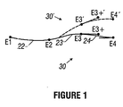
- Fig. 1 is a diagram showing movement of a composite curve on a computer display.
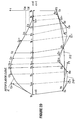
- Fig. 2A is a diagram illustrating a two-step mapping scheme used to calculate the displacement of control points defining a composite curve in response to movement of selected segment end points.
- Fig. 2B is a flow diagram of the two-step mapping scheme.
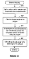
- Fig. 2C is a flow diagram of a distance mapping method used in the two-step mapping scheme.
- Fig. 2D is a diagram of a two-step mapping scheme of the modification of the slope of a composite curve at a curve end point.
- Fig. 2E is a flow diagram of the two-step mapping scheme of the modification of the slope of a composite curve at a curve end point.
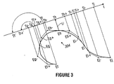
- Fig. 3 is a diagram of a projection mapping method to map points on a composite curve to an orthogonal line.
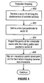
- Fig. 4 is a flow diagram of the projection mapping method.
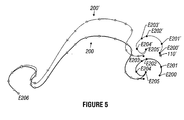
- Fig. 5 is a diagram showing movement of a composite curve in which multiple control points are selected and moved rigidly as a group.
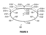
- Fig. 6 is a diagram showing movement of a closed-path curve.
- Fig. 7A is a diagram showing movement of a composite curve having disjoint groups of moved points.
- Fig. 7B is a diagram showing movement of two composite curves.
- Fig. 8 is a diagram showing modification of the slope of a composite curve at a curve end point.
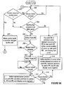
- Fig. 9A is a flow diagram of a method creating a Bezier curve segment.
- Fig. 9B is a diagram showing of a Bezier curve segment being created by a user.
- Fig. 10A is a diagram of a Bezier curve segment along with associated control points and vectors.
- Fig. 10B is a diagram of a composite curve having multiple Bezier curve segments.
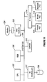
- Fig. 11 is a block diagram of a computer system.
- Fig. 12 is a diagram of a Bezier curve segment.
- a portion of a composite curve is selected to be modified or distorted in a manner specified by a user
- other portions of the curve are modified to maintain the general shape and details of the curve and to maintain smooth transitions between the segments of the entire curve. For example, if a composite curve includes hundreds of curve segments defining many details in the curve, the program will retain the details of the original composite curve after the modification operation. With the program, the user does not need to manually adjust the segments of the composite curve to retain the details and smoothness of the curve.
- the program also allows a user to adjust the slope of a composite curve at its curve end points.
- a slope adjustment point is provided which is selectable by the user to modify the slope by any desired amount.
- a composite curve is made up of a number of segments connected end to end.
- composite Bezier curve 30 has three Bezier segments 22, 23, and 24.
- the end points of segments are identified with the letter E followed by a number: in this example the segment end points are E1 through E4.
- the curve end points are E1 and E4.
- a segment end point that is not a curve end point is shared by two segments: in this example, these are E2 and E3.
- Bezier segments have another kind of control point, the slope point.
- Each end point in a segment is associated with one slope point.
- end points P0 and P3 are associated with slope points P1 and P2, respectively.
- the slope points associated with an end point En are identified as En+ and En-.
- the slope point of segment 22 associated with E2 is E2-, while the slope point of segment 23 associated with E2 is E2+.
- control points are moved.
- the control points in their new, post-move positions are identified by an apostrophe. If two moves are shown, the second positions are identified by two apostrophes, and so on.
- new control points E3', E3+', and E4' are shown.
- a segment end point may also be identified generically as P, and its associated slope control points as P+ and P-.
- the slope of the composite curve-at its curve end points can also be adjusted by the user by selecting what are referred to as "pseudo" slope points, which are described below in connection with Figs. 2D, 2E, and 8.
- each control point When a user moves a curve, the user marks each control point as being of one of three types: selected, free, and fixed. Normally, all control points will be free by default, and user actions will explicitly mark (through the graphical user interface of the program) particular control points as selected or fixed. Slope points of the curve segments are invisible to the user on the graphical user interface of the program, and thus cannot be marked as selected or fixed. Alternatively, the segment end points can default to fixed points (while slope points default to free points), with the user having to mark which segment end points are free or selected.
- Selected points are those points that move as a rigid group by a displacement specified by the user.
- Fixed points are those points that do not move.
- Free points are all other points whose displacements are calculated as will be described. However, the free points (including slope points E1+ and E2-) that are bounded solely by fixed points will remain in place.
- free points bounded solely by selected points normally will move with the selected points, depending upon the nature of the curve modification.
- Free segment end points are moved so as to maintain the general shape of the curve.
- Free slope points are moved so as to maintain smooth transitions between curve segments.
- a program determines the displacements of each free end point P along with associated slope points P- and P+ using an algorithm that performs a two-step mapping function.
- the program receives at step 400 a displacement V of a selected end point or selected end points on a composite curve.
- the program determines at step 401 if there are two or more disjoint groups of points. In a move operation that involves multiple disjoint groups of points to be moved, multiple separate mappings are performed. Two groups of selected points are considered disjoint if they are separated by a fixed point. Further, disjoint groups of control points also can occur if multiple composite curves are being moved at the same time. In the multiple-curve case, each composite curve is considered to contain at least one disjoint group of control points.
- control points on the composite curve are mapped at step 402 to points on one unit line segment t [0,1], as shown in Fig. 2A, using either a distance mapping method (Fig. 2C) or a projection mapping method (Figs. 3A and 3B).
- Fig. 2C a distance mapping method
- Figs. 3A and 3B a projection mapping method
- Each segment end point Ep (or simply P) on the composite curve is mapped to a point called Tp on t; each slope point Ep+ or Ep- (or simply P+ or P-), to a parameter Tp+ or Tp-.
- one interpolation curve IC is defined at step 403 on t.
- the points Tp are projected perpendicularly at step 404 from t onto the interpolation curve IC to obtain the values of parameters Cp.
- the shape of the interpolation curve IC(t) determines the value of parameters Cp, Cp-, and Cp+ and thus the amount of displacement of each of the free points.
- a cubic interpolation curve IC(t) is optimal for most applications involving third order Bezier segments.
- a differently shaped interpolation curve, such as a fifth degree polynomial or even a sine wave, will cause the free points to move differently.
- Selection of the shape of the interpolation curve IC(t) is application specific and is normally done by the manufacturer of the graphics program to produce the optimal behavior of the free points for the specific application. Once the interpolation curve IC(t) is set, then the same interpolation curve defined on the line segment t will be used for all curve distort operations.
- Fig. 2A shows an interpolation curve IC associated with one portion 300 of a composite curve in which point Ee is a selected point and point Ea is a fixed point.
- the interpolation curve IC is extended from Ce down to the line t on the other side of point Ee to form generally a bell-shaped curve.
- each group of control points is mapped at step 405 to points Tp, Tp-, and Tp+ on a corresponding one of unit line segments t1-tN.
- interpolation curves IC(t1)-IC(tN) are defined at step 406 on the line t1-tN, respectively, and points on the line segments t1-tN are in turn mapped at step 407 to parameters Cp, Cp-, and Cp+ on the interpolation curves IC(t1)-IC(tN).
- the same interpolation curve IC is used in each case as defined on line segment t [0, 1].
- step 404 or 407 the program calculates displacements for each free control point P-, and P+ using the parameters Cp, Cp-, and Cp+.
- the program then moves at step 412 the free points by the calculated displacements.
- step 410 the displacements are expressed in terms of new positions P-', P', and P+' using the parameters Cp-, Cp or Cp+ as scale factors to scale the vector displacement V.
- Each scaled displacement is then added to the corresponding original point to derive new points P-', P', and P+', as shown in Eqs. 1-3.
- P -' P - + V * Cp - ( Eq. 1)
- P ' P + V * Cp ( Eq. 2)
- P +' P + + V * Cp + ( Eq. 3)
- Equation 4 ensures that if the vectors (P+ - P) and (P - P-) are collinear in the original composite curve (as is required for a smooth Bezier curve), then the vectors will remain collinear in the distorted curve.
- a "bendable" section 300 of a composite curve that is, the section between the fixed point Ea and the selected point Ee.
- the other segment end points Eb, Ec, and Ed and slope points Ea+, Eb-, Eb+, Ec-, Ec+, Ed-, Ed+, and Ee- are free points whose displacements are calculated.
- the fixed segment end point Ea and the selected segment end point Ee are mapped to parameters Ta and Te, and the free points Ea+, Eb-, Eb, Eb+, Ec-, Ec, Ec+, Ed-, Ed, Ed+, and Ee- are mapped to parameters Ta+, Tb-, Tb, Tb+, Tc-, Tc, Tc+, Td-, Td, Td+, and Te-, respectively, along line t.
- a polyline 302 is first defined at step 420 that includes line segments that pass through the control points Ea, Ea+, Eb-, Eb, Eb+, Ec-, Ec, Ec+, Ed-, Ed, Ed+, Ee- and Ee.
- the total length L of the polyline 302 is calculated at step 422. Then, for each point P, P-, or P+, a length Dp, Dp-, or Dp+ (length of polyline 302 from point Ea to point Ep, Ep-, or Ep+) is calculated at step 424.
- the parameter Ta has value zero, since the length from point Ea to itself is zero.
- the parameter Ta+ is the length Da+ of the polyline 302 from point Ea to point Ea+ divided by the total length L of the polyline 302.
- the parameter Tb- is the length Db- of the polyline 302 from point Ea to Ea+ and from Ea+ to Eb- divided by the total length L of the polyline 302.
- the other parameters Tb through Te are calculated in similar fashion. Since the line segment t is defined between 0 and 1, the value of parameter Te is 1.
- distance mapping causes the points Ea through Ee to be mapped onto the straight line t according to the Euclidean distance between each point.
- Fig. 2A shows mapping to line segment t between the values 0 and 1.
- the mapping could be to a line segment t between any two arbitrary values as long as the distance relationships between the control points on the polyline are maintained.
- distance mapping Although one advantage of distance mapping is its simplicity, it also has limitations.
- One limitation of distance mapping is that the distortion of the composite curve is not reversible. Thus, for example, if a selected control point is then moved through a vector V to distort the curve, and the point is then moved through the opposite vector -V, the curve control points will not always return to their original locations if distance mapping is used.
- Projection mapping another mapping scheme for mapping points onto the line t, avoids this limitation in certain cases.
- the program first receives at step 450 a vector U that defines the direction of movement of a selected point or points.
- a vector U that defines the direction of movement of a selected point or points.
- line t is defined at step 452 to be perpendicular to the vector U.
- each of the control points Ef, Ef+, Eg-, Eg, Eg+, Eh-, Eh, Eh+, Ei-, Ei, Ei+, Ej-, and Ej is projected at step 454 onto the line t along a path that is parallel to the vector U to obtain a corresponding parameter Tf, Tf+, Tg-, Tg, Tg+, Th-, Th, Th+, Ti-, Ti, Ti+, Tj-, and Tj.
- projection mapping maps control points along corresponding parallel vectors to an orthogonal line t.
- Another mapping scheme can be used to map onto the line t.
- this third scheme assuming there are N+1 control points, the control points are mapped onto the straight line such that the distance between each control point is equal, that is, the distance between each control point is 1/N.
- This third mapping scheme has the advantage in that it is completely reversible.
- the shape of the composite curve resulting from a distort operation is highly dependent on the location of control points. If the control points are generally equally dispersed throughout the composite curve, then the distortion of the curve will be smooth over its entire length. However, if some control points are bunched together in clusters while other control points are farther apart, then there could be more abrupt changes in the shape of the curve after the distort operation.
- the program determines at step 456 if the parameters along the line t are monotonic, that is, Tf is less than Tf+, Tf+ is less than Tg-, Tg- is less than Tg, and so forth. If the parameters Ty are monotonic, nothing further is done. Otherwise, the non-monotonic points Tp, Tp-, or Tp+ are flipped at step 458 about the point Tp at which the projection-mapping became non-monotonic.
- the parameters Tf and Tf+ are each greater in value than the parameter Tg for point Eg.
- the parameters Tf and Tf+ are "unfolded" about the point where the mapping reverses direction (in this case parameter Tg-) to new parameters Tf' and Tf+', respectively.
- the distance between Tg- and Tf' is the same as the distance between Tg- and Tf
- the distance between Tg- and Tf+' is the same as the distance between Tg- and Tf+.
- Projection mapping is reversible because for displacements in opposite directions, the line t onto which the points are projected will be the same (that is, perpendicular to the vectors through which the selected points are dragged), and therefore the t values will be the same. Consequently, the distortions of the curve will be exactly reversed if a curve is first dragged through a vector U followed by a drag through a vector -U without any intervening operation.
- Projection mapping is more calculation intensive than distance mapping.
- the path through which the selected points are dragged to distort the composite curve is not likely to follow a straight line, but rather, the path of the cursor in a single drag operation is approximated as a succession of multiple vector displacements V1, V2, ... ., Vn from a common point.
- the parameters Cp-, Cp+, and Cp must be reapplied for each vector displacement V1, V2, . . ., Vn.
- the parameters Tp and Cp must be recalculated for each vector displacement V1, V2, . .
- the second step of the mapping scheme maps the parameters Tp, Tp-, and Tp+ to scale factors Cp, Cp-, and Cp+ derived from the interpolation curve IC for control points between Ea and Ee.
- Parameters Tb, Tc, and Td associated with free segment end points are mapped to points on the interpolation curve IC.
- the value of the parameter Ce is 1, since the point Ee is the selected point dragged through a displacement V with the cursor, and the value of the parameter Ca is zero since it is associated with the fixed point Ea.
- a composite curve 310 is associated with a single, approximating Bezier curve segment 312, which approximates the composite curve 310 using a least squares fit to points sampled from the composite curve 310.
- the approximating Bezier segment 312 is defined by segment end points P0 and P3 and slope points P1 and P2 (referred hereinafter as "pseudo" slope points P1 and P2 of the composite curve 310).
- the approximating segment 312 is strictly a user interface function to allow the user to adjust the slope at either curve end point Ea or curve end point Ee of the composite curve 310.
- Alternative schemes can be used for modifying the slope at curve end points.
- a simpler user interface method is to define pseudo slope points P1 and P2 along a line defined between end points P0 and P3, with point P1 at a position 1/3 and point P2 at a position 2/3 along the line.
- the program can provide a button in the user interface selectable by the user to enter into a slope adjustment mode. Then the user can mark which curve end point is to be modified and drag an arbitrary slope adjustment point to provide a displacement vector of the slope adjustment point to adjust the slope of the composite at one of its curve end points.
- the program calculates displacements for the control points of the composite curve using a two-step mapping scheme similar to that described above for movement of segment end points.
- the difference is in the interpolation curve used in the slope modification mapping steps.
- the interpolation curve must be defined such that the displacements of control points near the point P1 are larger than the other control points. Only the slope at one curve end point is adjusted, with the slope at the opposite curve end point remaining unchanged.
- the displacement vector V of pseudo slope point P1 is received at step 440.
- the program maps the control points Ea, Ea+, Eb-, Eb, Eb+, Ec-, Ec, Ec+, Ed-, Ed, Ed+, Ee-, and Ee onto a line segment t, using either distance mapping or projecting mapping (with distance mapping shown in Fig. 2D).
- the points Ta+, Tb-, Tb, Tb+, Tc-, Tc, Tc+, Td-, Td, Td+, and Te- are then mapped at step 446 onto the interpolation curve IC(t).
- the program calculates at step 448 the values of scale factors Cp, Cp-, and Cp+ to determine the displacements of the control points Ea through Ee. Then, at step 449, the control points are moved by the program by the calculated displacements.
- a point does not necessarily correspond to a point Tp, Tp+, or Tp- associated with a composite curve control point.
- the slope of any segment end point in a composite curve can be modified.
- the program displays an approximating curve between that segment end point and the segment end point at the other end of the portion of the composite curve the user wants to select. For example, in Fig. 2D, if the portion of the composite curve to be affected is between points Eb and Ed, and the slope at Eb is to be modified, then the approximating curve will be defined between points Eb and Ed.
- Pseudo slope point P1 of the shortened approximating curve can then be dragged to modify the slope at the segment end point Eb. Note that modifying the slope at segment end point Eb (since it is not a curve end point) will destroy the smooth transition between the affected curve segment (between Eb and Ec) and its adjacent curve segment (between Ea and Eb).
- Figs. 5-8 Exemplary curve distortions are shown below in Figs. 5-8, in which an original curve is represented with solid lines and a modified or distorted curve is represented with dashed lines where they differ from the original curve.
- a multi-segment composite curve 200 can be modified by the techniques of the invention to produce a composite curve 200'.
- the fixed point is the segment end point E206
- the selected points are segment end points E200, E201, E202, E203, E204 and E205, which are dragged as a group to new segment end points E200'-E205', respectively.
- the displacements of the free points between the fixed segment end point E206 and the selected segment end point E205 are determined by the program to maintain the general shape and detail of the original curve 200 and the smoothness of transitions between the curve segments.
- the path modification techniques can also be applied to cyclic, or closed, curves, such as the oval 120 defined by four Bezier segments 122, 123, 124, and 125 between segment end points E120, E121, E122, E123, and E124.
- the only new consideration is that the points need to be dealt with cyclically, that is, the first and last points are considered adjacent.
- the oval 120 is modified from original path 120 to new path 120', with segment end point E120 being the fixed point and the segment end point E123 being the selected point.
- the remaining points are free points whose displacements are calculated by the program to maintain the circular shape of the composite curve 120'.
- Figs. 7A and 7B illustrate disjoint groups of control points moved by the program.
- a six-segment composite curve 320 is distorted to a curve 320' with segment end points E320, E323, and E326 being fixed points and segment end points E321 and E324 being selected points.
- the control points between fixed points E320 and E323 form a first group of control points and the control points between fixed points E323 and E326 form a second group of control points. Separate mappings are performed for the two groups to determine the displacements of the free control points.
- Fig. 7B illustrates four disjoint groups of control points, with two groups in composite curve 220 and two groups in composite curve 230.
- the fixed points are segment end points E220, E223, E225, E231, and E235, and the selected points are segment end points E221, E224, E230, and E234.
- displacements of free points in the four disjoint groups are calculated using four separate mappings (with a mapping defined being the mapping required for control points between two fixed points). Again the slope points are adjusted to maintain the smooth transitions of the curve segments in the two composite curves 220' and 230'.
- Fig. 8 illustrates the modification of the slope of a composite curve 320 at curve end point P0.
- the composite curve 320 includes multiple Bezier curve segments (not shown explicitly).
- Pseudo slope point P1 is moved by a displacement vector V to point P1', and the slope of the composite curve 320 is adjusted accordingly to create composite curve 320'.
- the approximating curve 322 is moved to curve 322'.
- the pseudo slope points P1' and P2 can be further moved.
- a Bezier segment is defined by four control points P0, P1, P2, and P3, in which points P0 and P3 are segment end points and points P1 and P2 are slope points.
- the program creates and displays a curve between segment end point P0 and the cursor at the time the mouse button is pressed, and tracks the cursor with a "rubber band" Bezier segment using the current cursor position as the instantaneous location of the segment end point P3 and calculated positions for slope points P1 and P2, as will be described.
- the program determines at step 500 if the mouse button is pressed. If so, the program checks at step 501 if the cursor is located within a predetermined radius of a control point of an existing Bezier curve segment. If so, the program at step 502 moves the control point to a position indicated by the cursor.
- the program recognizes that curve segment creation is desired, and the program next determines at step 503 if a modifier key (e.g., Ctr1 key) is pressed or if no other curve is displayed on the computer screen.
- a modifier key e.g., Ctr1 key
- the first segment end point P0 is defined at step 504 as the point of the cursor when the user pressed the mouse button.
- the program detects at step 506 when the mouse button to be released.
- the position of the cursor at the time of release is defined at step 508 as an intermediate slope point S1, as shown in Fig. 10A.
- the point S1 is selected by the user to indicate the direction of a vector S from point P0 to point S1. Slope point P1 will be located along a line in the direction of the vector S. Further, the curve segment is tangent the vector S at the segment end point P0.
- the program determines at step 510 if the mouse button has been pressed again. If so, then the current position of the cursor is defined at step 512 as the position of the segment end point P3. The slope points P1 and P2 are also calculated at step 512 for the current position of the segment end point P3, and the curve segment is displayed to provide user feedback of the shape of the curve segment.
- the positions of points P1 and P2 are calculated by the program in step 512 so that the curve is a close approximation of an arc of a circle that goes through P0 and the cursor, as shown in Fig. 9B.
- the instantaneous position of the segment end point P3 follows the cursor (as indicated by points P3, P3', and P3"), and the slope points P1 and P2 are recalculated (as indicated by points P1, P2; P1', P2'; and P1", P2") to maintain an approximation of a circular arc.
- the program determines at step 514 if the mouse button has been released. If not, the current position of the cursor continues to indicate the position of the segment end point P3. If the mouse button is released, then the final position of the segment end point P3 is specified at step 516 as being the position of the cursor when the mouse button was released. The final positions of slope points P1 and P2 are also calculated and the curve segment is displayed.
- the program assumes that the user desires to create the next segment of a composite curve. As shown in Fig. 10B, the point P2 of the first curve segment 600 is reflected through the point P3 to define the position of the intermediate slope point S1' for the next curve segment 602.
- the line (P2 - P3) is collinear with the line (P3 - S1') to create a smooth transition between the curve segments 600 and 602.
- the current position of the cursor is used as the instantaneous position of the segment end point P3' of the new curve segment 602, and the positions of slope points P1' and P2' of the curve segment 602 are calculated as the segment end point P3' changes positions.
- the program detects at step 514 if the mouse button has been released, at which time the final position of the segment end point P3' is determined. The process described above can be applied to create additional curve segments to add to the composite curve.
- Equations 7-13 the mathematics for calculating the positions of slope points P1 and P2 is presented in Equations 7-13.
- the points P0, P1, P2, P3, and S1 are expressed as vectors in an arbitrary coordinate system.
- W P3 - P0 ( Eq. 7)
- S S1 - P0 ( Eq. 8)
- sA W ⁇ S /
- m 2*
- v 1 - (2* m * cosA /
- P1 P0 + m * S /
- P2 P1 + v * W ( Eq. 13)
- Equation 9 calculatescalar values m and v, with the value m used as a scale factor of a unit vector pointing in the direction of the S vector to derive the vector P1 in Equation 11, and the value v used as a scale factor of the vector W to derive the vector P2 in Equation 12.
- a program for creating and modifying curves in accordance with this specification may be implemented in digital electronic circuitry or in computer hardware, firmware, software, or in combinations of them, such as in a computer system 500.
- the computer system 500 includes a central processing unit (CPU) 502 connected to a internal system bus 504.
- the storage media in the computer system 500 include a main memory 506 (which can be implemented with dynamic random access memory devices), a hard disk drive 508 for mass storage, and an electrically erasable programmable read only memory (EEPROM) 510.
- the main memory 506 and EEPROM 510 are connected to the bus 504, and the hard disk drive 508 is coupled to the bus 504 through a hard disk drive controller 512.
- Apparatus of the invention may be implemented in a computer program product tangibly embodied in a machine-readable storage device (such as the hard disk drive 508, main memory 506, or EEPROM 510) for execution by the CPU 502.
- Suitable processors include, by way of example, both general and special purpose microprocessors.
- a processor will receive instructions and data from the read-only memory 510 and/or the main memory 506.
- Storage devices suitable for tangibly embodying computer program instructions include all forms of non-volatile memory, including by way of example semiconductor memory devices, such as EPROM, EEPROM, and flash memory devices; magnetic disks such as the internal hard disk drive 508 and removable disks; magneto-optical disks; and CD-ROM disks. Any of the foregoing may be supplemented by, or incorporated in, specially-designed ASICs (application-specific integrated circuits).
- the computer system 500 further includes an input/output (I/O) controller 514 connected to the bus 504 and which provides a keyboard interface 516 (for connection to an external keyboard), a mouse interface 518 (for connection to an external mouse or other pointer device), and a parallel port interface 520 (for connection to a printer).
- I/O input/output
- the bus 504 is connected to a video controller 522 which couples to an external computer monitor or display 524. Data associated with an image for display on the computer monitor 524 (such as the curves) are provided over the system bus 504 by application programs to the video controller 522.
- the various received commands can be provided to a computer in a number of different ways; for example, mouse gestures, keyboard strokes, and a graphical user interface can be used to communicate the commands to the computer system.
Landscapes
- Physics & Mathematics (AREA)
- General Physics & Mathematics (AREA)
- Engineering & Computer Science (AREA)
- Theoretical Computer Science (AREA)
- Image Generation (AREA)
- Processing Or Creating Images (AREA)
- Numerical Control (AREA)
Applications Claiming Priority (2)
| Application Number | Priority Date | Filing Date | Title |
|---|---|---|---|
| US08/761,186 US6111588A (en) | 1996-12-05 | 1996-12-05 | Creating and modifying curves on a computer display |
| US761186 | 1996-12-05 |
Publications (3)
| Publication Number | Publication Date |
|---|---|
| EP0847028A2 true EP0847028A2 (fr) | 1998-06-10 |
| EP0847028A3 EP0847028A3 (fr) | 1999-11-03 |
| EP0847028B1 EP0847028B1 (fr) | 2004-01-14 |
Family
ID=25061433
Family Applications (1)
| Application Number | Title | Priority Date | Filing Date |
|---|---|---|---|
| EP97308772A Expired - Lifetime EP0847028B1 (fr) | 1996-12-05 | 1997-10-31 | Méthode et programme pour la création et modification de courbes sur l'écran d'ordinateur |
Country Status (5)
| Country | Link |
|---|---|
| US (1) | US6111588A (fr) |
| EP (1) | EP0847028B1 (fr) |
| JP (1) | JP4153065B2 (fr) |
| CA (1) | CA2220375A1 (fr) |
| DE (1) | DE69727200T2 (fr) |
Cited By (3)
| Publication number | Priority date | Publication date | Assignee | Title |
|---|---|---|---|---|
| WO2000063847A1 (fr) * | 1999-04-16 | 2000-10-26 | Avid Technology, Inc. | Procede et systeme d'edition de courbes de fonctions dans deux dimensions |
| GB2391349B (en) * | 2001-12-20 | 2006-05-31 | Schlumberger Holdings | Designing the trajectory of a well bore |
| WO2009117619A1 (fr) * | 2008-03-20 | 2009-09-24 | Qualcomm Incorporated | Tessellation à étapes multiples pour rendu graphique |
Families Citing this family (61)
| Publication number | Priority date | Publication date | Assignee | Title |
|---|---|---|---|---|
| US8352400B2 (en) | 1991-12-23 | 2013-01-08 | Hoffberg Steven M | Adaptive pattern recognition based controller apparatus and method and human-factored interface therefore |
| AUPP557898A0 (en) * | 1998-08-28 | 1998-09-24 | Canon Kabushiki Kaisha | Method and apparatus for orientating a character stroke |
| US6674435B1 (en) * | 1998-09-16 | 2004-01-06 | Texas Instruments Incorporated | Fast, symmetric, integer bezier curve to polygon conversion |
| US7966078B2 (en) | 1999-02-01 | 2011-06-21 | Steven Hoffberg | Network media appliance system and method |
| US6462739B1 (en) * | 1999-03-18 | 2002-10-08 | Abode Systems Incorporated | Curve smoothing without shrinking |
| JP4427127B2 (ja) * | 1999-04-28 | 2010-03-03 | 東芝医用システムエンジニアリング株式会社 | 関心領域形状の修正方法および医用画像表示装置 |
| US6784886B1 (en) * | 2000-08-28 | 2004-08-31 | Adobe Systems Incorporated | Method for apparatus for associating objects with a spline by value |
| US6765589B1 (en) * | 2000-11-16 | 2004-07-20 | Adobe Systems Incorporated | Brush for warping and water reflection effects |
| US6963350B1 (en) | 2001-07-03 | 2005-11-08 | Adobe Systems Incorporated | Painting interface to computer drawing system curve editing |
| US8576232B2 (en) * | 2001-12-31 | 2013-11-05 | Siemens Product Lifecycle Management Software Inc. | Apparatus, method, and system for drafting multi-dimensional drawings |
| GB2406028A (en) * | 2003-09-11 | 2005-03-16 | Autodesk Canada Inc | Tangent handle adjustment for Bezier curves |
| US8442331B2 (en) | 2004-02-15 | 2013-05-14 | Google Inc. | Capturing text from rendered documents using supplemental information |
| US7707039B2 (en) | 2004-02-15 | 2010-04-27 | Exbiblio B.V. | Automatic modification of web pages |
| EP1562138B1 (fr) * | 2004-02-06 | 2009-08-19 | Dassault Systèmes | Méthode pour dessiner une courbe dans un système de conception assistée par ordinateur |
| US7812860B2 (en) | 2004-04-01 | 2010-10-12 | Exbiblio B.V. | Handheld device for capturing text from both a document printed on paper and a document displayed on a dynamic display device |
| US10635723B2 (en) | 2004-02-15 | 2020-04-28 | Google Llc | Search engines and systems with handheld document data capture devices |
| US9116890B2 (en) | 2004-04-01 | 2015-08-25 | Google Inc. | Triggering actions in response to optically or acoustically capturing keywords from a rendered document |
| US8146156B2 (en) | 2004-04-01 | 2012-03-27 | Google Inc. | Archive of text captures from rendered documents |
| US9143638B2 (en) | 2004-04-01 | 2015-09-22 | Google Inc. | Data capture from rendered documents using handheld device |
| US7990556B2 (en) | 2004-12-03 | 2011-08-02 | Google Inc. | Association of a portable scanner with input/output and storage devices |
| US20060081714A1 (en) | 2004-08-23 | 2006-04-20 | King Martin T | Portable scanning device |
| US9008447B2 (en) | 2004-04-01 | 2015-04-14 | Google Inc. | Method and system for character recognition |
| US8081849B2 (en) | 2004-12-03 | 2011-12-20 | Google Inc. | Portable scanning and memory device |
| US20060098900A1 (en) | 2004-09-27 | 2006-05-11 | King Martin T | Secure data gathering from rendered documents |
| US7894670B2 (en) | 2004-04-01 | 2011-02-22 | Exbiblio B.V. | Triggering actions in response to optically or acoustically capturing keywords from a rendered document |
| US8713418B2 (en) | 2004-04-12 | 2014-04-29 | Google Inc. | Adding value to a rendered document |
| US8874504B2 (en) | 2004-12-03 | 2014-10-28 | Google Inc. | Processing techniques for visual capture data from a rendered document |
| US8489624B2 (en) | 2004-05-17 | 2013-07-16 | Google, Inc. | Processing techniques for text capture from a rendered document |
| US8620083B2 (en) | 2004-12-03 | 2013-12-31 | Google Inc. | Method and system for character recognition |
| DE102004022320A1 (de) * | 2004-05-06 | 2005-11-24 | Daimlerchrysler Ag | Elektronische Konstruktionsvorrichtung |
| US8346620B2 (en) | 2004-07-19 | 2013-01-01 | Google Inc. | Automatic modification of web pages |
| US7433504B2 (en) * | 2004-08-27 | 2008-10-07 | General Electric Company | User interactive method for indicating a region of interest |
| JP4255449B2 (ja) * | 2005-03-01 | 2009-04-15 | 株式会社ソニー・コンピュータエンタテインメント | 描画処理装置、テクスチャ処理装置、およびテセレーション方法 |
| US7405733B2 (en) * | 2005-03-24 | 2008-07-29 | Autodesk Canada Co. | Spline drawing in a computer-implemented graphics program |
| US7643970B2 (en) * | 2005-11-09 | 2010-01-05 | The Boeing Company | Tape course generation method and apparatus for programming a composite tape lamination machine |
| EP2067119A2 (fr) | 2006-09-08 | 2009-06-10 | Exbiblio B.V. | Scanners optiques, tels que des scanners optiques portables |
| ATE501472T1 (de) * | 2007-01-18 | 2011-03-15 | Studer Ag Fritz | Verfahren zum ansteuern eines verfahrbaren werkzeugs, eingabevorrichtung sowie bearbeitungsmaschine |
| JP4540123B2 (ja) * | 2007-04-10 | 2010-09-08 | 富士フイルム株式会社 | 曲線修正方法および装置並びにプログラム |
| US7969440B1 (en) * | 2007-05-02 | 2011-06-28 | Evernote Corporation | Method and system for curve fitting using digital filtering |
| US8014630B1 (en) | 2007-05-02 | 2011-09-06 | Evernote Corporation | Method and apparatus for representing image data using digital filtering and adaptive parameterization |
| CN101354639A (zh) * | 2007-07-25 | 2009-01-28 | 联想(北京)有限公司 | 在终端之间操作对象的方法及终端 |
| JP2009271909A (ja) * | 2008-04-08 | 2009-11-19 | Canon Inc | 図形描画編集システム、図形描画編集装置及び図形描画編集方法 |
| KR20100070733A (ko) * | 2008-12-18 | 2010-06-28 | 삼성전자주식회사 | 아이템 표시방법 및 이를 적용한 디스플레이 장치 |
| WO2010096191A2 (fr) | 2009-02-18 | 2010-08-26 | Exbiblio B.V. | Informations de capture automatique telles que des informations de capture utilisant un dispositif prenant en charge des documents |
| EP2406767A4 (fr) | 2009-03-12 | 2016-03-16 | Google Inc | Fourniture automatique de contenu associé à des informations capturées, de type informations capturées en temps réel |
| US8447066B2 (en) | 2009-03-12 | 2013-05-21 | Google Inc. | Performing actions based on capturing information from rendered documents, such as documents under copyright |
| US9081799B2 (en) | 2009-12-04 | 2015-07-14 | Google Inc. | Using gestalt information to identify locations in printed information |
| US9323784B2 (en) | 2009-12-09 | 2016-04-26 | Google Inc. | Image search using text-based elements within the contents of images |
| US8521484B2 (en) * | 2010-06-02 | 2013-08-27 | Livermore Software Technology Corp. | Curve matching for parameter identification |
| TWI476640B (zh) | 2012-09-28 | 2015-03-11 | Ind Tech Res Inst | 時間資料序列的平滑化方法與裝置 |
| US20140098142A1 (en) * | 2012-10-09 | 2014-04-10 | School Yourself, Inc. | System and method for generation and manipulation of a curve in a dynamic graph based on user input |
| CN105765502B (zh) | 2013-11-19 | 2019-10-08 | 株式会社和冠 | 用于墨水数据生成、墨水数据呈现、墨水数据操纵以及墨水数据通信的方法和系统 |
| RU2608885C2 (ru) * | 2014-06-30 | 2017-01-25 | Общество С Ограниченной Ответственностью "Яндекс" | Способ определения точки кривой, ближайшей к позиции на карте |
| CN107767429B (zh) * | 2016-08-18 | 2021-11-16 | 阿里巴巴集团控股有限公司 | 曲线生成方法及设备 |
| CN109521731B (zh) * | 2017-09-19 | 2021-07-30 | 沈阳高精数控智能技术股份有限公司 | 一种基于公差带的G2连续Bézier刀具轨迹平滑算法 |
| CN111443864B (zh) * | 2020-04-14 | 2023-03-07 | 重庆赋比兴科技有限公司 | 基于iOS的曲线绘制方法 |
| CN114491377B (zh) * | 2020-11-13 | 2024-07-26 | 北京广利核系统工程有限公司 | 应用于核电站的斜率计算方法及装置 |
| US11321884B1 (en) * | 2021-03-19 | 2022-05-03 | Adobe Inc. | Generating candidate mirror snap points using determined axes of symmetry |
| US11769281B2 (en) * | 2022-02-01 | 2023-09-26 | Adobe Inc. | Vector object transformation |
| US12541891B2 (en) * | 2022-06-23 | 2026-02-03 | Adobe Inc. | Generating chain pull painting styles in digital applications |
| US12243135B2 (en) | 2022-11-04 | 2025-03-04 | Adobe Inc. | Vector object blending |
Family Cites Families (20)
| Publication number | Priority date | Publication date | Assignee | Title |
|---|---|---|---|---|
| CA1274919A (fr) * | 1985-07-27 | 1990-10-02 | Akio Ohba | Methode et dispositif de formage de surfaces galbees |
| US4760548A (en) * | 1986-06-13 | 1988-07-26 | International Business Machines Corporation | Method and apparatus for producing a curve image |
| GB2204216B (en) * | 1987-04-30 | 1991-02-06 | Ibm | Curve generation in a display system |
| JP3000101B2 (ja) * | 1987-08-19 | 2000-01-17 | 洋 牧野 | 軌跡制御補間方法 |
| KR930002339B1 (ko) * | 1989-04-20 | 1993-03-29 | 가부시기가이샤 도시바 | 짧은 직선 벡터의 곡선 세그멘트에 3차 베지어(Bzxier)곡선을 정합시키는 방법 |
| FR2646256A1 (fr) * | 1989-04-24 | 1990-10-26 | Digital Equipment Int | Procede pour realiser des dessins a l'aide d'un ordinateur |
| JPH03127186A (ja) * | 1989-10-12 | 1991-05-30 | Mitsubishi Electric Corp | 描画方式 |
| US5317682A (en) * | 1989-10-24 | 1994-05-31 | International Business Machines Corporation | Parametric curve evaluation method and apparatus for a computer graphics display system |
| JP2734711B2 (ja) * | 1990-01-12 | 1998-04-02 | 日本電気株式会社 | 曲線発生装置 |
| JP3049096B2 (ja) * | 1990-12-20 | 2000-06-05 | 株式会社リコー | 曲面間のフィレット面生成方式 |
| JP3137245B2 (ja) * | 1991-10-30 | 2001-02-19 | ソニー株式会社 | 自由曲線作成方法及び自由曲面作成方法 |
| EP0551543A1 (fr) * | 1992-01-16 | 1993-07-21 | Hewlett-Packard GmbH | Procédé de modification d'un objet géométrique et système de conception assistée par ordinateur |
| US5588100A (en) * | 1992-05-18 | 1996-12-24 | Microsoft Corporation | Method and system for creating a freeform drawing object |
| US5367617A (en) * | 1992-07-02 | 1994-11-22 | Microsoft Corporation | System and method of hybrid forward differencing to render Bezier splines |
| JPH06110992A (ja) * | 1992-09-25 | 1994-04-22 | Agency Of Ind Science & Technol | Cadシステムにおける形状変形入力操作方法 |
| US5715473A (en) * | 1992-12-29 | 1998-02-03 | Apple Computer, Inc. | Method and apparatus to vary control points of an outline font to provide a set of variations for the outline font |
| US5500927A (en) * | 1993-03-18 | 1996-03-19 | Macromedia, Inc. | System and method for simplifying a computer-generated path |
| US5594852A (en) * | 1994-08-17 | 1997-01-14 | Laser Products, Inc. | Method for operating a curve forming device |
| US5566288A (en) * | 1994-09-02 | 1996-10-15 | Caterpillar Inc. | System and method for automatically fitting a B-spline curve to a set of data points |
| US5694535A (en) * | 1995-03-24 | 1997-12-02 | Novell, Inc. | Direct interactive, constant-time curve apparatus and method |
-
1996
- 1996-12-05 US US08/761,186 patent/US6111588A/en not_active Expired - Lifetime
-
1997
- 1997-10-31 EP EP97308772A patent/EP0847028B1/fr not_active Expired - Lifetime
- 1997-10-31 DE DE69727200T patent/DE69727200T2/de not_active Expired - Lifetime
- 1997-11-06 CA CA002220375A patent/CA2220375A1/fr not_active Abandoned
- 1997-12-05 JP JP33537997A patent/JP4153065B2/ja not_active Expired - Fee Related
Cited By (5)
| Publication number | Priority date | Publication date | Assignee | Title |
|---|---|---|---|---|
| WO2000063847A1 (fr) * | 1999-04-16 | 2000-10-26 | Avid Technology, Inc. | Procede et systeme d'edition de courbes de fonctions dans deux dimensions |
| US6469702B1 (en) | 1999-04-16 | 2002-10-22 | Avid Technology, Inc. | Method and system for editing function curves in two dimensions |
| GB2391349B (en) * | 2001-12-20 | 2006-05-31 | Schlumberger Holdings | Designing the trajectory of a well bore |
| WO2009117619A1 (fr) * | 2008-03-20 | 2009-09-24 | Qualcomm Incorporated | Tessellation à étapes multiples pour rendu graphique |
| US8643644B2 (en) | 2008-03-20 | 2014-02-04 | Qualcomm Incorporated | Multi-stage tessellation for graphics rendering |
Also Published As
| Publication number | Publication date |
|---|---|
| DE69727200T2 (de) | 2004-10-14 |
| JPH10293859A (ja) | 1998-11-04 |
| EP0847028B1 (fr) | 2004-01-14 |
| US6111588A (en) | 2000-08-29 |
| DE69727200D1 (de) | 2004-02-19 |
| EP0847028A3 (fr) | 1999-11-03 |
| JP4153065B2 (ja) | 2008-09-17 |
| CA2220375A1 (fr) | 1998-06-05 |
Similar Documents
| Publication | Publication Date | Title |
|---|---|---|
| EP0847028B1 (fr) | Méthode et programme pour la création et modification de courbes sur l'écran d'ordinateur | |
| JP6869249B2 (ja) | 2つのタイプのインクベクトルデータを生成して選択的に出力する方法及びシステム | |
| US4731606A (en) | Method for rapid windowing of display information in computer graphics | |
| CN100433064C (zh) | 在基于扫描线的光栅图像处理器中跟踪深度的方法 | |
| KR102385256B1 (ko) | 디지털 잉크의 스무딩 및 gpu-구동 렌더링 | |
| WO2002047033A1 (fr) | Dispositif de generation de donnees caracteres 3-d et dispositif de generation de donnees graphiques 3-d | |
| GB2313028A (en) | Method of transforming a basic shape element of a character | |
| US5303321A (en) | Integrated hardware generator for area fill, conics and vectors in a graphics rendering processor | |
| CN109101171A (zh) | 一种在触摸屏设备中生成滑动轨迹的方法 | |
| US6201542B1 (en) | Three-dimensional polygon display apparatus using progressive polygon data | |
| US5664071A (en) | Graphics plotting apparatus and method | |
| CN116547718A (zh) | 用户界面 | |
| CN111462205B (zh) | 图像数据的变形、直播方法、装置、电子设备和存储介质 | |
| JP2003250039A (ja) | 画像処理装置,画像処理方法および記録媒体 | |
| EP0623231A1 (fr) | Unite de commande videographique a capacites ameliorees de production de configurations de pixels. | |
| JPH0567216A (ja) | 図形塗りつぶし装置 | |
| WO2006019022A1 (fr) | Dispositif de mise en correspondance, procede de mise en correspondance et son programme | |
| CN111127589B (zh) | 顾及线宽一致性的矢量地图圆形虚线符号绘制方法 | |
| JP3479282B2 (ja) | 文字図形変形処理装置 | |
| JP2686012B2 (ja) | 太線描画方法 | |
| CN114187383B (zh) | 曲线渲染方法、装置、计算机设备及存储介质 | |
| JP3268484B2 (ja) | シェーディング方法およびシェーディング装置 | |
| JP2768331B2 (ja) | 曲線の直線近似装置 | |
| JPH0424774A (ja) | 曲線描画機能を備えた情報処理装置および処理方法 | |
| JP2748787B2 (ja) | 曲線発生装置 |
Legal Events
| Date | Code | Title | Description |
|---|---|---|---|
| PUAI | Public reference made under article 153(3) epc to a published international application that has entered the european phase |
Free format text: ORIGINAL CODE: 0009012 |
|
| AK | Designated contracting states |
Kind code of ref document: A2 Designated state(s): DE FR GB |
|
| AX | Request for extension of the european patent |
Free format text: AL;LT;LV;RO;SI |
|
| PUAL | Search report despatched |
Free format text: ORIGINAL CODE: 0009013 |
|
| AK | Designated contracting states |
Kind code of ref document: A3 Designated state(s): AT BE CH DE DK ES FI FR GB GR IE IT LI LU MC NL PT SE |
|
| AX | Request for extension of the european patent |
Free format text: AL;LT;LV;RO;SI |
|
| 17P | Request for examination filed |
Effective date: 20000502 |
|
| AKX | Designation fees paid |
Free format text: DE FR GB |
|
| 17Q | First examination report despatched |
Effective date: 20020614 |
|
| RTI1 | Title (correction) |
Free format text: METHOD AND PROGRAM FOR CREATING AND MODIFYING CURVES ON A COMPUTER DISPLAY |
|
| GRAP | Despatch of communication of intention to grant a patent |
Free format text: ORIGINAL CODE: EPIDOSNIGR1 |
|
| GRAS | Grant fee paid |
Free format text: ORIGINAL CODE: EPIDOSNIGR3 |
|
| GRAA | (expected) grant |
Free format text: ORIGINAL CODE: 0009210 |
|
| AK | Designated contracting states |
Kind code of ref document: B1 Designated state(s): DE FR GB |
|
| PG25 | Lapsed in a contracting state [announced via postgrant information from national office to epo] |
Ref country code: FR Free format text: LAPSE BECAUSE OF FAILURE TO SUBMIT A TRANSLATION OF THE DESCRIPTION OR TO PAY THE FEE WITHIN THE PRESCRIBED TIME-LIMIT Effective date: 20040114 |
|
| REG | Reference to a national code |
Ref country code: GB Ref legal event code: FG4D |
|
| REF | Corresponds to: |
Ref document number: 69727200 Country of ref document: DE Date of ref document: 20040219 Kind code of ref document: P |
|
| PLBE | No opposition filed within time limit |
Free format text: ORIGINAL CODE: 0009261 |
|
| STAA | Information on the status of an ep patent application or granted ep patent |
Free format text: STATUS: NO OPPOSITION FILED WITHIN TIME LIMIT |
|
| 26N | No opposition filed |
Effective date: 20041015 |
|
| EN | Fr: translation not filed | ||
| PGFP | Annual fee paid to national office [announced via postgrant information from national office to epo] |
Ref country code: DE Payment date: 20161025 Year of fee payment: 20 Ref country code: GB Payment date: 20161026 Year of fee payment: 20 |
|
| REG | Reference to a national code |
Ref country code: DE Ref legal event code: R071 Ref document number: 69727200 Country of ref document: DE |
|
| REG | Reference to a national code |
Ref country code: GB Ref legal event code: PE20 Expiry date: 20171030 |
|
| PG25 | Lapsed in a contracting state [announced via postgrant information from national office to epo] |
Ref country code: GB Free format text: LAPSE BECAUSE OF EXPIRATION OF PROTECTION Effective date: 20171030 |