EP0847071B1 - Kathode für eine elektronenröhre - Google Patents
Kathode für eine elektronenröhre Download PDFInfo
- Publication number
- EP0847071B1 EP0847071B1 EP96904298A EP96904298A EP0847071B1 EP 0847071 B1 EP0847071 B1 EP 0847071B1 EP 96904298 A EP96904298 A EP 96904298A EP 96904298 A EP96904298 A EP 96904298A EP 0847071 B1 EP0847071 B1 EP 0847071B1
- Authority
- EP
- European Patent Office
- Prior art keywords
- alkaline
- earth metal
- crystalline particles
- metal carbonate
- dendritic
- Prior art date
- Legal status (The legal status is an assumption and is not a legal conclusion. Google has not performed a legal analysis and makes no representation as to the accuracy of the status listed.)
- Expired - Lifetime
Links
Images


Classifications
-
- H—ELECTRICITY
- H01—ELECTRIC ELEMENTS
- H01J—ELECTRIC DISCHARGE TUBES OR DISCHARGE LAMPS
- H01J1/00—Details of electrodes, of magnetic control means, of screens, or of the mounting or spacing thereof, common to two or more basic types of discharge tubes or lamps
- H01J1/02—Main electrodes
- H01J1/13—Solid thermionic cathodes
- H01J1/14—Solid thermionic cathodes characterised by the material
- H01J1/142—Solid thermionic cathodes characterised by the material with alkaline-earth metal oxides, or such oxides used in conjunction with reducing agents, as an emissive material
Definitions
- This invention relates to cathodes for electron tubes used for a cathode ray tube (CRT), etc., and relates in particular to improvement of the emitter thereof.
- CRT cathode ray tube
- cathodes for electron tubes which comprise a base mainly comprising nickel and including a reducing element such as silicon and magnesium coated with alkaline-earth metal carbonate crystalline particles and thermally decomposed in a vacuum to generate an emitter mainly comprising an alkaline-earth metal oxide, have been used broadly.
- FIG. 8 - FIG. 10 Scanning electron microscope images illustrating the shapes of representative alkaline-earth metal carbonate crystalline particles used for an emitter of cathodes conventionally used for electron tubes are shown in FIG. 8 - FIG. 10.
- Various shapes of the alkaline-earth metal carbonate crystalline particles are known such as spherical represented by FIG. 8, dendritic represented by FIG. 9, and bar-like represented by FIG. 10.
- an aggregate of crystalline particles having the same shape, namely, only spherical particles or only dendritic particles JP-A-3-280322
- the "same shape” herein denotes the shape of crystalline particles obtained under the same synthetic conditions, and thus strictly speaking, individual crystalline particles may have slight variations in size or shape, but the shape of one kind by a geometric classification is suggested.
- the above mentioned emitter mainly comprising an alkaline-earth metal oxide produced by coating the cathode base with an alkaline-earth metal carbonate and thermally decomposing in a vacuum
- the emitter since the emitter is maintained at a temperature around 700 °C in a usual CRT operation state, a problem occurs in that the entire emitter gradually has thermal shrinkage as time passes.
- the thermal shrinkage triggers the gradual drift of the cut-off voltage to cut off the emission (hereinafter called cut-off drift).
- cut-off drift amount The amount of the cut-off drift (hereinafter called cut-off drift amount) varies depending upon the shape of the crystalline particles of the above mentioned alkaline-earth metal carbonate; and the cut-off drift amount is smaller in the dendritic than in the bar-like, and smaller in the spherical than in the dendritic.
- the emission characteristic varies depending upon the above mentioned shape; and the emission characteristic is better in the dendritic than in the spherical, and better in the bar-like than in the dendritic.
- a vacuum a high vacuum of 10 -6 Torr or less herein
- the saturation current remaining ratio is the normalized value of the saturation current with respect to the operation time based on the initial value of the saturation current as 1 (the ratio of the saturation current with respect to the operation time in the case of setting the initial value of the saturation current as 1), and it can be said that the larger the saturation current remaining ratio, the better the emission characteristic.
- the operation conditions in FIG. 11 and FIG. 12 are that the voltage of the heater to heat the cathode is operated at a 10 % increased rate with respect to the ordinary use condition to accelerate the change with the passage of time, the so-called examination results under the accelerated conditions.
- FIG. 11 and FIG. 12 denote the results when the alkaline-earth metal carbonate crystalline particles of the spherical form having an average diameter of 0.7 ⁇ m, the dendritic form having an average length of 5 ⁇ m, and the bar-like form having an average length of 7 ⁇ m illustrated in FIG. 8, FIG. 9, FIG. 10 respectively are used as the material.
- the length of the dendritic crystals is the length between the edge of the trunk to the farthest edge of the branch on the opposite side.
- the object of the present invention is to solve the problem in the above mentioned conventional example to provide a cathode for electron tube improved both in the cut-off drift and in the emission characteristic of the cathode for electron tube.
- EP-A-416535 EP-A-330355, EP-A-445956, EP-A-204477, EP-A-482704 and JP-A-47016994.
- the present invention relates to a cathode for an electron tube as described in claim 1.
- a cathode for an electron tube of the present invention comprises a base for the cathode for the electron tube, coated with an alkaline-earth metal carbonate containing at least barium as the alkaline-earth metal, and thermally decomposed in a vacuum to generate an emitter mainly comprising an alkaline-earth metal oxide, wherein a mixture of two or more kinds of alkaline-earth metal carbonate crystalline particles having different shapes is used as the alkaline-earth metal carbonate.
- alkaline-earth metal carbonates containing barium used in the present invention are not particularly limited, but alkaline-earth metal carbonates containing 40 mol % or more of barium as the alkaline-earth metal component are preferably used.
- Alkaline-earth metal carbonates containing other alkaline-earth metal components such as strontium and calcium together with barium as an alkaline-earth metal component can be used preferably as well.
- alkaline-earth metal carbonates containing barium and strontium are preferably used, for example, binary carbonates such as barium-strontium carbonate or ternary carbonates such as barium-strontium-calcium carbonate are preferably used.
- alkaline-earth metal carbonates containing 40 mol % or more of barium and 30 mol % or more of strontium as a component of alkaline-earth metal are preferable.
- alkaline-earth metal carbonates a mixture of two or more kinds of alkaline-earth metal carbonate crystalline particles having different shapes is used.
- "Different shapes” denotes shapes classified geometrically in different groups from a macroscopic point of view. For example, taking the spherical crystalline particles, even when the variety in size or shape of the crystalline particles exists, if the crystalline particles are nearly spherical, they are not described as different shapes.
- alkaline-earth metal carbonate crystalline particles obtained under the same synthetic conditions have the same shape, and thus in order to obtain a mixture of alkaline-earth metal carbonate crystalline particles having two or more kinds of different shapes, alkaline-earth metal carbonate crystalline particles having different shapes obtained from two or more kinds of different synthetic conditions respectively are mixed and used.
- spherical alkaline-earth metal carbonate crystalline particles can be obtained by adding an aqueous solution of sodium carbonate as the precipitant to an aqueous solution of an alkaline-earth metal nitrate to precipitate the crystals of the alkaline-earth metal carbonate and drying after filtration.
- ammonium hydrogencarbonate can be used as the precipitant in place of sodium carbonate in the above mentioned synthetic method.
- dendritic alkaline-earth metal carbonate crystalline particles ammonium carbonate can be used as the precipitant in place of sodium carbonate in the above mentioned synthesis method.
- the mixing of alkaline-earth metal carbonate crystalline particles having different shapes can be carried out by, for example, mechanically mixing crystalline particles having two or more kinds of different shapes with an agitator. Further, it is preferable to add a rare earth metal oxide such as europium oxide, yttrium oxide, dysprosium oxide, scandium oxide, lanthanum oxide, and gadolinium oxide in the range of 20 weight % or less to the alkaline-earth metal carbonate, since it can further improve the emission characteristic of the cathode of the present invention.
- a rare earth metal oxide such as europium oxide, yttrium oxide, dysprosium oxide, scandium oxide, lanthanum oxide, and gadolinium oxide
- the mixing ratio of the alkaline-earth metal carbonate crystalline particles having two or more kinds of different shapes is not particularly limited, and if even a little amount of crystalline particles of another shape is mixed, it contributes to the improvement of the cut-off drift and the emission characteristic compared with the case of crystalline particles having the shape of only one kind, but favorably it is preferable to contain crystalline particles of each shape at the ratio of about 0.2 or more based on the entire weight ratio respectively.
- a base usually used can be used, and thus it is not particularly limited.
- a base mainly comprising nickel and containing a reducing element such as silicon and magnesium is used, and as the reducing element, although it is not particularly limited, at least one kind from silicon, magnesium, aluminum, thallium, etc. is used.
- the amount of the reducing element is not particularly limited, but it is in general, about 0.05 to 0.8 weight % in total based on the weight of the base.
- a method of dispersing the above mentioned mixture of alkaline earth metal carbonate crystalline particles in an organic medium, which does not dissolve the alkaline-earth metal carbonate crystalline particles and preferably has a comparatively low boiling point, to form a dispersion, and spraying the dispersion to the base of a cathode with a spray gun and drying is generally used, but it is not limited to this method.
- organic media for the dispersion ethyl nitrate, ethyl acetate, diethyl oxalate can be illustrated as typical examples, but it is not limited thereto, and other organic media can be used as long as they have a comparatively low boiling point and do not dissolve a carbonate nor react with a carbonate.
- the thickness of the above mentioned mixture of alkaline-earth metal carbonate crystalline particles coated on the base of the cathode for electron tube cannot be prescribed sweepingly since it varies depending upon the kind of the electron tube, etc., but for example, it is about 30 - 80 ⁇ m.
- alkaline-earth metal carbonate crystalline particles coated as heretofore described to the base of the cathode for electron tube are thermally decomposed in a vacuum to form an alkaline-earth metal oxide.
- alkaline-earth metal oxide it depends on the kind of the contained alkaline-earth metal, in general, they are thermally decomposed in a high vacuum of 10 -6 Torr or less at a high temperature of 900 °C or more.
- the alkaline-earth metal carbonate containing barium and strontium with the composition ratio (molar ratio) of 1 : 1 as the alkaline-earth metal, and comprising the spherical crystalline particles having an average diameter of 0.7 ⁇ m shown in FIG. 8 and the dendritic crystalline particles having an average longer axis of 5 ⁇ m shown in FIG. 9 mixed at the weight ratio of 1 : 1 will be explained.
- the above mentioned spherical alkaline-earth metal carbonate crystalline particles were obtained by dissolving barium nitrate and strontium nitrate at the molecular ratio of 1 : 1 in water, adding an aqueous solution of sodium carbonate as the precipitant to precipitate the crystals of barium-strontium carbonate, filtering and then drying.
- the above mentioned dendritic alkaline-earth metal carbonate crystalline particles were obtained using the same conditions as mentioned above except that an aqueous solution of ammonium carbonate was used as the precipitant in place of an aqueous solution of sodium carbonate.
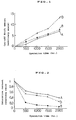
- FIG. 1 The state of the cut-off drift with respect to the operation time when the obtained cathode was used as the cathode of the CRT is shown in FIG. 1, and the saturation current remaining ratio, which is one of the indicators of the emission characteristics, is shown in FIG. 2.
- FIG. 2 the saturation current remaining ratio, which is one of the indicators of the emission characteristics.
- Solid lines “A” in FIG. 1 and FIG. 2 denote this example, and dotted lines “a”, “b” are conventional examples shown in FIG. 11 and FIG. 12 partially described for comparison.
- “a” is the case where only the spherical crystalline particles having an average diameter of 0.7 ⁇ m shown in FIG. 8 were used, and
- “b” is the case where only the dendritic crystalline particles having an average longer axis of 5 ⁇ m shown in FIG. 9 were used as the alkaline-earth metal carbonate.
- the cut-off drift amount of "A” which is a mixture of the spherical crystalline particles and the dendritic crystalline particles of this example, is smaller than the cut-off drift amount of "b”, which includes only the dendritic crystalline particles of the conventional technology, and shows the value equivalent or slightly smaller than the cut-off drift amount of "a”, which includes only the spherical crystalline particles. That is, it can be said that the characteristics concerning the cut-off drift of "A" are equivalent or superior to the others, "a” and "b".
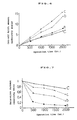
- the saturation current remaining ratio of "A” which is the case when the spherical crystalline particles and dendritic crystalline particles were mixed and used according to this embodiment, is larger than the saturation current remaining ratio of "a”, which includes only the spherical form of the conventional technology, and slightly larger than the saturation current remaining ratio of "b”, which includes only the dendritic form. That is, it can be said that the emission characteristic of "A” is superior to others, "a", "b". Accordingly, it can be learned that both the cut-off drift and the emission characteristic can be improved at the same time by this invention illustrated in this example.
- the average diameter of the spherical crystalline particles was 0.7 ⁇ m and the average length of the dendritic crystalline particles was 5 ⁇ m, and the mixing ratio of the spherical crystalline particles and the dendritic crystalline particles was 1 : 1 by weight ratio in the above mentioned first example, these values are representative and thus other various combinations of values can be used, and the experiment results are shown in FIG. 3 collectively.
- the horizontal axis of FIG. 3 illustrates the weight ratio "R" of the spherical crystalline particles with respect to the dendritic crystalline particles, and the vertical axis illustrates the cut-off drift amount after 2000 hours of operation under the acceleration conditions.
- the alkaline-earth metal carbonate containing barium and strontium with the composition ratio (molar ratio) of 1 : 1 as the alkaline-earth metal, and comprising the spherical crystalline particles having an average diameter of 0.7 ⁇ m shown in FIG. 8 and the bar-like crystalline particles having an average length of 7 ⁇ m shown in FIG. 10 mixed at the weight ratio of 1 : 1 will be explained.
- the bar-like alkaline-earth metal carbonate crystalline particles were obtained by dissolving barium nitrate and strontium nitrate at the molecular ratio of 1 : 1 in water, adding an aqueous solution of ammonium hydrogen carbonate as the precipitant to precipitate the crystals of barium-strontium carbonate, filtering and then drying.
- the other conditions are the same as the first example, and hereinafter in the same process, 3 weight % of scandium oxide was included in the mixture of the alkaline-earth metal carbonate crystalline particles, coated on the cathode base, and thermally decomposed in a vacuum to generate an emitter mainly comprising alkaline-earth metal oxide.
- the state of the cut-off drift with respect to the operation time when it was used as the cathode of the CRT is shown in FIG. 4, and the saturation current remaining ratio is shown in FIG. 5.
- the operation conditions of the CRT were the accelerated conditions.
- Solid lines “B” in FIG. 4 and FIG. 5 denote this example, and dotted lines “a”, “c” are conventional examples shown in FIG. 11 and FIG. 12 partially described for comparison.
- “a” is the case where only the spherical crystalline particles having an average diameter of 0.7 ⁇ m shown in FIG. 8 were used, and
- “c” is the case where only the bar-like crystalline particles having an average length of 7 ⁇ m shown in FIG. 10 were used as the alkaline-earth metal carbonate.
- the cut-off drift amount of "B” which is the case of this example when the spherical crystalline particles and the bar-like crystalline particles were mixed and used is smaller than the cut-off drift amount of "c”, which includes only the bar-like crystalline particles of the conventional technology, and shows the value equivalent or slightly smaller than the cut-off drift amount of "a”, which includes only the spherical crystalline particles. That is, it can be said that the characteristics concerning the cut-off drift of "B” is equivalent or superior to the others, "a” and "c".
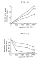
- the saturation current remaining ratio of "B” which is the case when the spherical crystalline particles and bar-like crystalline particles were mixed and used according to this embodiment, is larger than the saturation current remaining ratio of "a”, which includes only the spherical crystalline particles of the conventional technology, and slightly larger than the saturation current remaining ratio of "c", which includes only the bar-like crystalline particles. That is, it can be said that the emission characteristic of "B” is superior to the others, "a” and "c". Accordingly, it can be learned that both the cut-off drift and the emission characteristic can be improved at the same time by this invention, as illustrated in this example as well as in the first example.
- the alkaline-earth metal carbonate containing barium and strontium with the composition ratio (molar ratio) of 1 : 1 as the alkaline-earth metal, and comprising the spherical crystalline particles having an average diameter of 0.7 ⁇ m shown in FIG. 8, the dendritic crystalline particles having an average length of 5 ⁇ m shown in FIG. 9, and the bar-like crystalline particles having an average length of 7 ⁇ m shown in FIG. 10, mixed at the weight ratio of 1 : 1 : 1 will be explained.
- Alkaline-earth metal carbonate crystalline particles of each shape were synthetized according to the same method as in the preceding examples respectively, and other conditions are the same as in the preceding examples, and hereinafter in the same process, 3 weight % of scandium oxide was included in the mixture of the alkaline-earth metal carbonate crystalline particles, coated on the cathode base, and thermally decomposed in a vacuum to generate an emitter mainly comprising alkaline-earth metal oxide.
- the state of the cut-off drift with respect to the operation time when it was used as the cathode of the CRT is shown in FIG. 6, and the saturation current remaining ratio is shown in FIG. 7.
- the operation conditions of the CRT were the accelerated conditions.
- Solid lines “C” in FIG. 6 and FIG. 7 denote this example, and dotted lines “a”, “b”, “c” are conventional examples shown in FIG. 11 and FIG. 12 described for comparison.
- “a” is the case where only the spherical crystalline particles having an average diameter of 0.7 ⁇ m shown in FIG. 8 were used
- “b” is the case where only the dendritic crystalline particles having an average length of 5 ⁇ m shown in FIG. 9 were used
- “c” is the case where only the bar-like crystalline particles having an average length of 7 ⁇ m shown in FIG. 10 were used as the alkaline-earth metal carbonate.
- the cut-off drift amount of "C” which is the case when the spherical crystalline particles, the dendritic crystalline particles and the bar-like crystalline particles were mixed and used according to this embodiment, is smaller than the cut-off drift amount of "b”, which includes only the dendritic crystalline particles, or "c", which includes only the bar-like crystalline particles of the conventional technology, and shows the value equivalent or slightly smaller than the cut-off drift amount of "a”, which includes only the spherical crystalline particles of the conventional technology. That is, it can be said that the characteristics concerning the cut-off drift of "C” are equivalent or superior to the others, "a", "b” and "c".
- the saturation current remaining ratio of "C” which is the case when the spherical, dendritic and bar-like crystalline particles were mixed and used according to this embodiment is larger than the saturation current remaining ratio of "a”, which includes only the spherical of the conventional technology, or "b", which includes only the dendritic, and slightly larger than the saturation current remaining ratio of "c”, which includes only the bar-like crystalline particles and further larger compared with the saturation current remaining ratios in the first and second examples. That is, it can be said that the emission characteristic of "C” is not only superior to the others, “a”, “b", “c", but also superior to the first and second examples stated above.
- the mixing ratio in mixing the spherical, dendritic and the bar-like crystalline particles is not particularly limited but it is more effective when the crystalline particles of each shape are included in a ratio of 20 weight % or more respectively.
- alkaline-earth metal carbonates including barium and strontium by the composition ratio of 1 : 1 as the alkaline-earth metal were mentioned, by having the above mentioned composition ratio other than 1 : 1 or by including calcium in addition to barium and strontium as the above mentioned alkaline-earth metal, the effects of the present invention can be attained.
- the content ratio can be other than 3 weight %, for example, the content ratio can be 0 weight %, and for example, yttrium oxide or dysprosium oxide can be used in place of scandium oxide.
- a cathode for an electron tube having improved both cut-off drift and emission characteristic at the same time can be provided.
- the alkaline-earth metal carbonate is a mixture of three kinds of the spherical, dendritic and bar-like alkaline-earth metal carbonate crystalline particles, a cathode for electron tube having further improved cut-off drift and emission characteristic at the same time can be provided.
- the cathodes for electron tube of the present invention have the above mentioned effects, they can be effectively used as the cathode for electron tube which is used as the cathode for the cathode ray tube of a television or other CRTs, or as the electron gun of an electron microscope.
Landscapes
- Solid Thermionic Cathode (AREA)
Claims (1)
- Kathode für eine Elektronenröhre, die gebildet wird durch Beschichten einer Basis der Kathode für eine Elektronenröhre mit einem Erdalkalimetallkarbonat, das mindestens Barium als das Erdalkalimetall enthält, und thermische Zersetzung in einem Vakuum, um einen Emitter zu erzeugen, der hauptsächlich ein Erdalkalimetalloxid aufweist, wobei das Erdalkalimetallkarbonat besteht aus(a) einer Mischung von zwei Arten kristalliner Erdalkalimetallkarbonatteilchen, wobei die beiden Arten eine Kugelform und eine Form sind, die aus einer dendritischen Form mit Verzweigungen und einer stangenförmigen Form ausgewählt wird,
oder(b) einer Mischung von drei Arten kristalliner Erdalkalimetallkarbonatteilchen, wobei die drei Arten eine Kugelform, eine dendritische Form und eine stangenförmige Form sind,
wobei
in dem Fall, wo das Erdalkalimetallkarbonat die Mischung(a) ist, eine durchschnittliche Teilchengröße der dendritischen oder stangenförmigen kristallinen Erdalkalimetallkarbonatteilchen größer als eine durchschnittliche Teilchengröße der kugelförmigen kristallinen Erdalkalimetallkarbonatteilchen ist, und
in dem Fall, wo das Erdalkalimetallkarbonat die Mischung(b) ist, eine durchschnittliche Teilchengröße der stangenförmigen kristallinen Erdalkalimetallkarbonatteilchen größer als eine durchschnittliche Teilchengröße der dendritischen kristallinen Erdalkalimetallkarbonatteilchen ist und die durchschnittliche Teilchengröße der dendritischen kristallinen Erdalkalimetallkarbonatteilchen größer als eine durchschnittliche Teilchengröße der kugelförmigen kristallinen Erdalkalimetallkarbonatteilchen ist.
Applications Claiming Priority (1)
| Application Number | Priority Date | Filing Date | Title |
|---|---|---|---|
| PCT/JP1996/000493 WO1997032330A1 (en) | 1996-02-29 | 1996-02-29 | Electron-tube cathode |
Publications (3)
| Publication Number | Publication Date |
|---|---|
| EP0847071A1 EP0847071A1 (de) | 1998-06-10 |
| EP0847071A4 EP0847071A4 (de) | 2000-03-01 |
| EP0847071B1 true EP0847071B1 (de) | 2005-08-03 |
Family
ID=14152986
Family Applications (1)
| Application Number | Title | Priority Date | Filing Date |
|---|---|---|---|
| EP96904298A Expired - Lifetime EP0847071B1 (de) | 1996-02-29 | 1996-02-29 | Kathode für eine elektronenröhre |
Country Status (7)
| Country | Link |
|---|---|
| US (1) | US5959395A (de) |
| EP (1) | EP0847071B1 (de) |
| KR (1) | KR100252817B1 (de) |
| CA (1) | CA2188802C (de) |
| DE (1) | DE69635024T2 (de) |
| NO (1) | NO964573L (de) |
| WO (1) | WO1997032330A1 (de) |
Families Citing this family (3)
| Publication number | Priority date | Publication date | Assignee | Title |
|---|---|---|---|---|
| TW419688B (en) * | 1998-05-14 | 2001-01-21 | Mitsubishi Electric Corp | Cathod ray tube provided with an oxide cathod and process for making the same |
| JP2001006521A (ja) * | 1999-06-22 | 2001-01-12 | Nec Kansai Ltd | カソード構体およびカラーブラウン管 |
| FR2808377A1 (fr) * | 2000-04-26 | 2001-11-02 | Thomson Tubes & Displays | Cathode a oxydes pour tube a rayons cathodiques |
Family Cites Families (10)
| Publication number | Priority date | Publication date | Assignee | Title |
|---|---|---|---|---|
| JPS4716993Y1 (de) * | 1969-12-15 | 1972-06-14 | ||
| JPS4716994Y1 (de) * | 1969-12-15 | 1972-06-14 | ||
| JPS4716994A (de) * | 1969-12-15 | 1972-06-14 | ||
| KR900007751B1 (ko) * | 1985-05-25 | 1990-10-19 | 미쯔비시덴끼 가부시기가이샤 | 전자관 음극 및 그 제조방법 |
| KR910009660B1 (ko) * | 1988-02-23 | 1991-11-25 | 미쓰비시전기 주식회사 | 전자관용 산화물피복음극 |
| JPH06105585B2 (ja) * | 1988-03-01 | 1994-12-21 | 三菱電機株式会社 | 電子管用陰極 |
| JPH0393126A (ja) * | 1989-09-05 | 1991-04-18 | Sony Corp | 電子管用陰極 |
| JP2758244B2 (ja) * | 1990-03-07 | 1998-05-28 | 三菱電機株式会社 | 電子管用陰極 |
| JP3226041B2 (ja) * | 1990-03-28 | 2001-11-05 | 日亜化学工業株式会社 | エミッタ用アルカリ土類炭酸塩 |
| NL9002291A (nl) * | 1990-10-22 | 1992-05-18 | Philips Nv | Oxydekathode. |
-
1996
- 1996-02-29 WO PCT/JP1996/000493 patent/WO1997032330A1/ja not_active Ceased
- 1996-02-29 DE DE69635024T patent/DE69635024T2/de not_active Expired - Fee Related
- 1996-02-29 US US08/727,619 patent/US5959395A/en not_active Expired - Fee Related
- 1996-02-29 EP EP96904298A patent/EP0847071B1/de not_active Expired - Lifetime
- 1996-02-29 KR KR1019960706556A patent/KR100252817B1/ko not_active Expired - Fee Related
- 1996-02-29 CA CA002188802A patent/CA2188802C/en not_active Expired - Fee Related
- 1996-10-28 NO NO964573A patent/NO964573L/no not_active Application Discontinuation
Also Published As
| Publication number | Publication date |
|---|---|
| WO1997032330A1 (en) | 1997-09-04 |
| US5959395A (en) | 1999-09-28 |
| KR100252817B1 (ko) | 2000-04-15 |
| NO964573D0 (no) | 1996-10-28 |
| CA2188802A1 (en) | 1997-08-30 |
| DE69635024D1 (de) | 2005-09-08 |
| KR970706595A (ko) | 1997-11-03 |
| NO964573L (no) | 1997-09-04 |
| DE69635024T2 (de) | 2006-06-08 |
| CA2188802C (en) | 2001-12-11 |
| EP0847071A4 (de) | 2000-03-01 |
| EP0847071A1 (de) | 1998-06-10 |
Similar Documents
| Publication | Publication Date | Title |
|---|---|---|
| KR100342044B1 (ko) | 녹색발광 형광체 조성물 및 이를 이용하여 제조된 음극선관 | |
| EP0847071B1 (de) | Kathode für eine elektronenröhre | |
| US6222308B1 (en) | Emitter material for cathode ray tube having at least one alkaline earth metal carbonate dispersed or concentrated in a mixed crystal or solid solution | |
| EP0841676B1 (de) | Kathode für eine Elektronenröhre und Herstellungsverfahren | |
| CN1081386C (zh) | 电子管的阴极 | |
| CN1087482C (zh) | 电子管阴极 | |
| JP3411130B2 (ja) | 電子管用陰極 | |
| US5804098A (en) | Low-velocity electron excited phosphor | |
| US5982083A (en) | Cathode for electron tube | |
| CN1097278C (zh) | 电子管用阴极 | |
| KR100325859B1 (ko) | 금속염 코팅 녹색 발광 형광체 및 그의 제조방법 | |
| JPH1064404A (ja) | 陰極およびその製造方法 | |
| KR100329559B1 (ko) | 녹색 발광 형광체, 이를 포함하는 녹색발광 형광체 조성물 및 이를 이용하여 제조된 음극선관 | |
| JPH0891833A (ja) | バリウムを含むアルカリ土類金属炭酸塩樹枝状結晶の製造方法 | |
| JPH0233822A (ja) | 電子管用陰極 | |
| KR20000066210A (ko) | 녹색발광 형광체, 그 제조방법, 및 이를 이용하여 제조된 음극선관 | |
| JPH02247934A (ja) | 電子管用陰極 | |
| JPH10144202A (ja) | 電子管陰極およびその製造方法 | |
| JPH0684448A (ja) | 酸化物陰極 | |
| JPH1021819A (ja) | 電子管用陰極の製造方法 |
Legal Events
| Date | Code | Title | Description |
|---|---|---|---|
| PUAI | Public reference made under article 153(3) epc to a published international application that has entered the european phase |
Free format text: ORIGINAL CODE: 0009012 |
|
| 17P | Request for examination filed |
Effective date: 19961128 |
|
| AK | Designated contracting states |
Kind code of ref document: A1 Designated state(s): DE FR GB IT NL SE |
|
| A4 | Supplementary search report drawn up and despatched |
Effective date: 20000118 |
|
| AK | Designated contracting states |
Kind code of ref document: A4 Designated state(s): DE FR GB IT NL SE |
|
| RAP1 | Party data changed (applicant data changed or rights of an application transferred) |
Owner name: MATSUSHITA ELECTRIC INDUSTRIAL CO., LTD. |
|
| 17Q | First examination report despatched |
Effective date: 20030519 |
|
| GRAP | Despatch of communication of intention to grant a patent |
Free format text: ORIGINAL CODE: EPIDOSNIGR1 |
|
| GRAA | (expected) grant |
Free format text: ORIGINAL CODE: 0009210 |
|
| GRAS | Grant fee paid |
Free format text: ORIGINAL CODE: EPIDOSNIGR3 |
|
| AK | Designated contracting states |
Kind code of ref document: B1 Designated state(s): DE FR GB IT NL SE |
|
| PG25 | Lapsed in a contracting state [announced via postgrant information from national office to epo] |
Ref country code: NL Free format text: LAPSE BECAUSE OF FAILURE TO SUBMIT A TRANSLATION OF THE DESCRIPTION OR TO PAY THE FEE WITHIN THE PRESCRIBED TIME-LIMIT Effective date: 20050803 Ref country code: IT Free format text: LAPSE BECAUSE OF FAILURE TO SUBMIT A TRANSLATION OF THE DESCRIPTION OR TO PAY THE FEE WITHIN THE PRESCRIBED TIME-LIMIT;WARNING: LAPSES OF ITALIAN PATENTS WITH EFFECTIVE DATE BEFORE 2007 MAY HAVE OCCURRED AT ANY TIME BEFORE 2007. THE CORRECT EFFECTIVE DATE MAY BE DIFFERENT FROM THE ONE RECORDED. Effective date: 20050803 |
|
| REG | Reference to a national code |
Ref country code: GB Ref legal event code: FG4D |
|
| REF | Corresponds to: |
Ref document number: 69635024 Country of ref document: DE Date of ref document: 20050908 Kind code of ref document: P |
|
| PG25 | Lapsed in a contracting state [announced via postgrant information from national office to epo] |
Ref country code: SE Free format text: LAPSE BECAUSE OF FAILURE TO SUBMIT A TRANSLATION OF THE DESCRIPTION OR TO PAY THE FEE WITHIN THE PRESCRIBED TIME-LIMIT Effective date: 20051103 |
|
| NLV1 | Nl: lapsed or annulled due to failure to fulfill the requirements of art. 29p and 29m of the patents act | ||
| ET | Fr: translation filed | ||
| PLBE | No opposition filed within time limit |
Free format text: ORIGINAL CODE: 0009261 |
|
| STAA | Information on the status of an ep patent application or granted ep patent |
Free format text: STATUS: NO OPPOSITION FILED WITHIN TIME LIMIT |
|
| 26N | No opposition filed |
Effective date: 20060504 |
|
| PGFP | Annual fee paid to national office [announced via postgrant information from national office to epo] |
Ref country code: DE Payment date: 20070222 Year of fee payment: 12 |
|
| PGFP | Annual fee paid to national office [announced via postgrant information from national office to epo] |
Ref country code: GB Payment date: 20070228 Year of fee payment: 12 |
|
| PGFP | Annual fee paid to national office [announced via postgrant information from national office to epo] |
Ref country code: FR Payment date: 20070208 Year of fee payment: 12 |
|
| GBPC | Gb: european patent ceased through non-payment of renewal fee |
Effective date: 20080229 |
|
| REG | Reference to a national code |
Ref country code: FR Ref legal event code: ST Effective date: 20081031 |
|
| PG25 | Lapsed in a contracting state [announced via postgrant information from national office to epo] |
Ref country code: DE Free format text: LAPSE BECAUSE OF NON-PAYMENT OF DUE FEES Effective date: 20080902 |
|
| PG25 | Lapsed in a contracting state [announced via postgrant information from national office to epo] |
Ref country code: FR Free format text: LAPSE BECAUSE OF NON-PAYMENT OF DUE FEES Effective date: 20080229 |
|
| PG25 | Lapsed in a contracting state [announced via postgrant information from national office to epo] |
Ref country code: GB Free format text: LAPSE BECAUSE OF NON-PAYMENT OF DUE FEES Effective date: 20080229 |