EP0847153A2 - Procédé et appareil pour mésurer la qualité de forme d'onde signaux AMDC - Google Patents
Procédé et appareil pour mésurer la qualité de forme d'onde signaux AMDC Download PDFInfo
- Publication number
- EP0847153A2 EP0847153A2 EP19970121669 EP97121669A EP0847153A2 EP 0847153 A2 EP0847153 A2 EP 0847153A2 EP 19970121669 EP19970121669 EP 19970121669 EP 97121669 A EP97121669 A EP 97121669A EP 0847153 A2 EP0847153 A2 EP 0847153A2
- Authority
- EP
- European Patent Office
- Prior art keywords
- signal
- parameters
- measuring
- ideal
- parameter
- Prior art date
- Legal status (The legal status is an assumption and is not a legal conclusion. Google has not performed a legal analysis and makes no representation as to the accuracy of the status listed.)
- Granted
Links
Images

Classifications
-
- H—ELECTRICITY
- H04—ELECTRIC COMMUNICATION TECHNIQUE
- H04B—TRANSMISSION
- H04B1/00—Details of transmission systems, not covered by a single one of groups H04B3/00 - H04B13/00; Details of transmission systems not characterised by the medium used for transmission
- H04B1/69—Spread spectrum techniques
- H04B1/707—Spread spectrum techniques using direct sequence modulation
-
- G—PHYSICS
- G01—MEASURING; TESTING
- G01R—MEASURING ELECTRIC VARIABLES; MEASURING MAGNETIC VARIABLES
- G01R23/00—Arrangements for measuring frequencies; Arrangements for analysing frequency spectra
- G01R23/16—Spectrum analysis; Fourier analysis
-
- H—ELECTRICITY
- H04—ELECTRIC COMMUNICATION TECHNIQUE
- H04B—TRANSMISSION
- H04B17/00—Monitoring; Testing
- H04B17/10—Monitoring; Testing of transmitters
- H04B17/15—Performance testing
- H04B17/16—Test equipment located at the transmitter
-
- H—ELECTRICITY
- H04—ELECTRIC COMMUNICATION TECHNIQUE
- H04B—TRANSMISSION
- H04B17/00—Monitoring; Testing
- H04B17/20—Monitoring; Testing of receivers
- H04B17/21—Monitoring; Testing of receivers for calibration; for correcting measurements
- H04B17/22—Monitoring; Testing of receivers for calibration; for correcting measurements for calibration of the receiver components
- H04B17/221—Monitoring; Testing of receivers for calibration; for correcting measurements for calibration of the receiver components of receiver antennas, e.g. as to amplitude or phase
-
- H—ELECTRICITY
- H04—ELECTRIC COMMUNICATION TECHNIQUE
- H04B—TRANSMISSION
- H04B7/00—Radio transmission systems, i.e. using radiation field
- H04B7/24—Radio transmission systems, i.e. using radiation field for communication between two or more posts
- H04B7/26—Radio transmission systems, i.e. using radiation field for communication between two or more posts at least one of which is mobile
- H04B7/2628—Radio transmission systems, i.e. using radiation field for communication between two or more posts at least one of which is mobile using code-division multiple access [CDMA] or spread spectrum multiple access [SSMA]
-
- H—ELECTRICITY
- H04—ELECTRIC COMMUNICATION TECHNIQUE
- H04B—TRANSMISSION
- H04B2201/00—Indexing scheme relating to details of transmission systems not covered by a single group of H04B3/00 - H04B13/00
- H04B2201/69—Orthogonal indexing scheme relating to spread spectrum techniques in general
- H04B2201/707—Orthogonal indexing scheme relating to spread spectrum techniques in general relating to direct sequence modulation
Definitions
- the present invention relates to a method and apparatus for measuring the waveform quality of a CDMA (Code Division Multiple Access) modulated signal that is used in mobile communications or the like.
- CDMA Code Division Multiple Access
- a conventional method for measuring evaluation parameters of each channel signal in a radio wave radiated from a base station of CDMA mobile communications that is, a power coefficient ⁇ i , the output timing ⁇ i and a phase offset ⁇ i , is described, for example, in a thesis entitled “Overview of Code-Domain Power, Timing, and Phase Measurements", Hewlett-Packard Journal, pp.73-93, Feb. 1996.
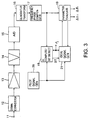
- a CDMA signal from a base station is inputted via an input terminal 11 into a down converter 12.
- the CDMA signal is converted by the down converter 12 to an IF signal which is, in turn, amplified by an amplifier 13.
- the amplified IF signal is band-limited by a filter 14 and converted by an A/D (analog-to-digital) converter 15 to a digital signal.
- the measuring signal (the CDMA signal), converted to digital form, is transformed by a quadrature transform part 16 to a complex base band signal.
- the base band signal is applied to a frequency/phase compensating part 17 wherein its frequency and phase shifts are compensated for.
- the compensated base band signal is applied to a ⁇ i computation/bit detection part 18 and a parameter evaluating part 19.
- a pilot signal generating part 20 is a means for generating a known pilot signal. Based on the known pilot signal from the pilot signal generating part 20 and the output from the frequency/phase compensating part 17, the ⁇ i computation/bit detection part 18 computes the power coefficient ⁇ i and detects a bit for each channel. The power coefficient ⁇ i and the bit thus detected are provided to an ideal signal generating part 21 which generates an ideal signal from the detected bit and power coefficient ⁇ i and the pilot signal fed from the pilot signal generating part 20. The ideal signal is applied to the parameter evaluating part 19.
- the parameter evaluating part 19 is also supplied with the output from the frequency/phase compensating part 17. Based on the both input signals, the parameter evaluating part 19 computes an output timing (a time lag) ⁇ i and a phase offset (a phase shift) ⁇ i of each of other channels relative to a pilot channel in the input signal (the CDMA signal) so as to minimize the mean square of the difference between the two input signals. The thus computed outputs ⁇ i and ⁇ i are fed back to the ideal signal generating part 21. The ideal signal generating part 21 re-creates and applies an ideal signal to the parameter evaluating part 19 which repeatedly computes the output timing ⁇ i and the phase offset ⁇ i .
- the above conventional method computes the output timing ⁇ i and the phase offset ⁇ i in the parameter evaluating part 19 through their optimization but does not involve optimization of the power coefficient ⁇ i .
- the computed power coefficient ⁇ i remains affected by the output timing ⁇ i and the phase offset ⁇ i , and hence its accuracy of measurement is low. Since the ideal signal generating part 21 uses the low-accuracy power coefficient ⁇ i to generate the ideal signal, the measured output timing and phase offset ⁇ i and ⁇ i also lack accuracy.
- Another object of the present invention is to provide a measuring apparatus with which it is possible to measure the waveform quality of the CDMA modulated signal with high accuracy.
- a method for measuring the waveform quality of a CDMA signal which comprises: a correcting steps of correcting a carrier frequency shift of a digital measuring signal transformed to a base band signal; a demodulating step of demodulating the corrected digital measuring signal to obtain demodulated data (bit data) and an amplitude value; an ideal signal generating step of generating an ideal signal based on the demodulated data, the amplitude value and estimated parameters; a parameter estimating step of estimating various parameters from the ideal signal and the corrected measuring signal; an optimization step of repeating the correction of the carrier frequency shift of the digital measuring signal in the correcting step and the generation of the ideal signal in the ideal signal generating step through utilization of the estimated parameters and repeating the demodulating step and the parameter estimating step until the estimated parameters are optimized; and a power coefficient computation step of computing the power coefficient of the measuring signal with the estimated parameters optimized.
- the correcting step corrects the measuring signal also using amplitude, time lag or delay and phase parameters of a specified channel thereof.
- the parameter estimating step estimates the amplitude, time lag or delay and phase parameters by solving approximate simultaneous equations of a parameter that minimizes the square of the difference between the measuring signal and the ideal signal.
- the parameter estimating step comprises a step of computing five pieces of auxiliary data A(k), B(k), C(k), I(k) and H(k) using the ideal signal, the amplitude parameter, the time lag or delay parameter, the phase parameter and a data number (time) k as variables, and a step of solving the approximate simultaneous equations through the use of the five pieces of auxiliary data and the measuring signal.
- an apparatus for measuring the waveform quality of a CDMA signal which comprises: analog-to-digital converting means for converting an input CDMA signal to a digital signal; quadrature transform and correcting means for transforming the digital signal to a digital measuring signal of the baseband and for correcting its carrier frequency shift; demodulating means for demodulating the corrected digital measuring signal to obtain its demodulated data and amplitude value; pilot signal generating means for generating a known pilot signal; means for generating an ideal signal from the demodulated data and the pilot signal and for generating auxiliary data from the ideal signal through calculation; parameter estimating means for estimating various parameters from the auxiliary data and the corrected digital measuring signal through calculation; means for updating estimated parameters used so far with the parameters currently estimated by the parameter estimating means; and power coefficient computation means for computing the power coefficient of the measuring signal with the estimated parameters optimized.
- storage means for storing the digital signal converted by the analog-to-digital converting means.
- the stored digital signal is read out from the storage means by the analog-to-digital converting means.
- the input signal is corrected using various parameters to create a measuring base band signal.
- demodulated data and an initially estimated amplitude value are detected from the measuring base band signal.
- ideal signal generating step an ideal signal is generated from the demodulated data, the amplitude value and other estimated parameters.
- parameter estimating step various parameters are estimated from the ideal signal and the measuring base band signal.
- optimizing step the estimated various parameters are used to optimize the generation of the measuring base band signal and the ideal signal, after which the demodulating step, the ideal signal generating step and the parameter estimating step are repeated. After the optimization the power coefficient of the measuring signal is computed in the power coefficient computation step.
- R ⁇ k i R i (t k + ⁇ i )exp(j[ ⁇ ⁇ (t k + ⁇ i )+ ⁇ i ])
- ⁇ ⁇ i the optimum value of i-th channel signal output timing
- ⁇ ⁇ is the optimum value of a carrier frequency error
- ⁇ ⁇ i the optimum value of the carrier phase of the i-th channel signal
- R i a i [ k g(t-kT c )cos ⁇ i,k +j k g(t-kT c )sin ⁇ i,k ]
- R i (t) a i [ k g(t-kT c )cos ⁇ i,k +j k g(t-kT c )sin ⁇ i,k ]
- the term inside the bracket [ ] represents an ideal signal whose amplitude is 1
- a ⁇ i is the optimum value of the amplitude of the i-th channel signal
- R ⁇ k can be expressed by the following equation (5):
- R k i a i ⁇ R' i (t k + ⁇ i )exp(j[ ⁇ ⁇ (t k + ⁇ i )+ ⁇ i ])
- R' 1 is the term inside the bracket [ ] in Eq. (4).
- the sampling of the measuring signal Z is repeated so that ⁇ ⁇ 0 is reduced down to zero. Consequently, optimized parameters will ultimately be determined from sampling data at the time when ⁇ ⁇ 0 becomes zero.
- k 1 64 Z j,k R i,j,k *
- 2 k 1 64
- 2 where j and k are symbols used in place of sampling numbers. If k until now is replaced with k', the Eq. (6) can be expressed by the following equation: k' k-1 + (j-1) ⁇ 64 In Eq. (6) R i,j,k is the same as R' used so far.
- the partial differential equation is a polynomial using a combination of parameters.
- the parameters are each determined by formulating simultaneous linear equations approximate to respective partial differential equations with terms of the second and subsequent orders of each parameter omitted and by solving the simultaneous linear equations.
- the following correction parameters ⁇ ', ⁇ ' i , ⁇ ' i and a' i are introduced.
- These parameters are optimized so that the parameters added with ⁇ will ultimately be zero.
- These parameters ⁇ ', ⁇ ' i , ⁇ ' i and a' i contain errors prior to their optimization.
- the parameter ⁇ ' is used as an estimated value before it is optimized. This parameter is used to correct the measuring signal in advance.
- the other parameters are used as estimated values prior to their optimization. These parameters are used to correct the ideal signal in advance.
- ⁇ is formulated in the equation of the ideal signal R.
- R is given as follows: R(t k )
- a digital filtering scheme is known as a method for obtaining a value displaced ⁇ from the sampled value R.
- R(t k - ⁇ ) Letting an impulse response of a suitable digital filter be represented by h(t), a ⁇ -shifted impulse response h(mT s - ⁇ ) is pre-computed.
- This impulse response is approximated by using a Taylor expansion around zero and leaving the equation down to the second order term.
- p p ( ⁇ ) ⁇ ⁇ + i p ( ⁇ a i ) ⁇ ⁇ a i + i p ( ⁇ i ) ⁇ ⁇ i + i p ( ⁇ i ) ⁇ ⁇ i +Const.
- p's are coefficients of respective terms. These p's form a coefficient matrix.
- the results of respective partial differentiations are shown below.
- the parameters ⁇ , ⁇ a i , ⁇ i , ⁇ i and Const. are shown at the left-hand side of a multiplication symbol " ⁇ " (dot) and coefficients p( ⁇ ), p( ⁇ a i ), p( ⁇ i ), p( ⁇ i ) and Const. at the right-hand side of the multiplication symbol " ⁇ ".
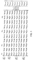
- the respective parameter values are obtained by solving the simultaneous equations as shown in Fig. 1 which are formed by a matrix of the coefficients p's and a matrix of the parameters ⁇ , ⁇ a i , ⁇ i and ⁇ i given above.
- the updated correcting parameters are used to correct the measuring signal Z and re-create the ideal signal, and the afore-mentioned optimization is repeated.
- Fig. 1 is a diagram showing simultaneous equations that are used for the estimation of parameters in an embodiment of the CDMA signal waveform quality measuring method according to the present invention
- Fig. 2 is a block diagram illustrating the general configuration of an embodiment of the CDMA signal waveform quality measuring apparatus according to the present invention.
- Fig. 3 is a block diagram showing the general configuration of a conventional CDMA signal waveform quality measuring apparatus.
- Fig. 2 illustrates in block form the configuration of an embodiment of the CDMA signal waveform quality measuring apparatus according to the present invention.
- the parts or components corresponding to those in Fig. 3 are identified by the same reference numerals and no description will be given unless necessary.
- the CDMA signal from a base station is inputted via the input terminal 11 into and converted by the down converter 12 to an IF signal which is amplified by the amplifier 13.
- the amplified IF signal is band-limited by the filter 14 and the converted by the A/D (analog-to-digital) converter 15 to digital form.
- the digital IF signal is temporarily stored in a memory 40 from which it is read out and applied to a quadrature transform part/complementary filter 22.
- the digital IF signal is first transformed in the quadrature transform part of the quadrature transform part/complementary filter 22 to a base band signal.
- the base band signal is passed through the complementary filter of the quadrature transform part/complementary filter 22 that is a receiving filter or measuring filter, by which it is converted to the base band measuring signal Z(k).
- the measuring signal Z(k) is applied to a demodulating part 25, wherein it is reverse-diffused or despread by the pilot signal (a PN code) from the pilot signal generating part 20.
- bit data is demodulated and at the same time the amplitude a' i of each channel is detected.
- an ideal signal/auxiliary data generating part 26 an ideal signal R i is generated from the bit data from the demodulating part 25 and the pilot signal (PN code) from the pilot signal generating part 20. Further, by computing the aforementioned Eqs. (10) through (14), auxiliary data are derived from the ideal signal R i .
- the ideal signal R i is produced as follows:
- the demodulated bit data from the demodulating part 25 is diffused by I- and Q-side pilot signals (PN codes) from the pilot signal generating part 20, respectively.
- chips "0" and "1" of the diffused I- and Q-side chip trains are converted to + ⁇ 2 and - ⁇ 2, respectively, to obtain I and Q signals of a QPSK signal whose amplitude is 1. That is, an amplitude-normalized ideal signal R i (k-m) is obtained.
- the ideal signal R i (k-m) and the amplitude a' i from the demodulating part 25 are used to compute the auxiliary data A i (k), B i (k), C i (k), I i (k) and H i (k) of Eqs. (10) through (14).
- auxiliary data A i (k), B i (k), C i (k), I i (k), H i (k) and the measuring signal Z(k) are inputted into a parameter estimating part 27, wherein the simultaneous equations depicted in Fig. 1 are solved to obtain respective estimated values ⁇ a i , ⁇ i , ⁇ i and ⁇ .
- these estimated values are used to update the previous correcting parameters a' 1 , ⁇ ' i , ⁇ ' i and ⁇ ' by Eq. (15).
- the updated correcting parameters a' i , ⁇ ' i , ⁇ ' i and ⁇ ' are used to correct the measuring signal Z(k).
- the thus corrected measuring signal Z(k) undergoes again the processes of the demodulating part 25, the ideal signal/auxiliary data generating part 26, the parameter estimating part 27 and the first transform part 28.
- This correcting process is repeated until the estimated values ⁇ a i , ⁇ i , ⁇ i , and ⁇ are optimized, that is, until they are reduced down to zero or a value close thereto, or until they remain unchanged.
- This repetition of the correcting process is the optimization step.
- the ideal signal R i as well as the measuring signal Z(k) are corrected.
- the correction of the measuring signal Z(k) is made by correcting the previous measuring signal Z(k) through the following calculation: Z(k) ⁇ Z(t- ⁇ ' 0 )(1/a' 0 )exp[-j( ⁇ '(t- ⁇ ' 0 )+ ⁇ ' 0 ]
- Eq. (16) is computed for the new parameters a' 0 , ⁇ ' 0 , ⁇ ' 0 , and ⁇ '.
- This correcting calculation is conducted on the signal that is inputted into the quadrature transform part/complementary filter 22, that is, on the output from the memory 40 (and consequently the output from the A/D converter 15).
- the correcting calculation may be conducted on the measuring signal Z(k) transformed to the baseband.
- this baseband-transformed measuring signal is a signal having passed through the complementary filter (a filter of the passband width as the bandwidth of the input signal). If the signal has a large frequency error, there is a fear that part of the signal is removed by the filtering, that is, a fear that the measuring signal to be used for the parameter estimation and so on is removed. For this reason, the result of the frequency estimation is corrected at a stage preceding the complementary filter.
- the correction may be made on the baseband-transformed measuring signal.
- the parameters for the ideal signals R i of channels other than the 0-th one are corrected by the parameters of the 0th channel to have the values given by Eq. (17).
- the auxiliary data generating part 26 uses, as correcting parameters, the parameters of the values normalized by the parameters of the 0-th channel by Eq. (17), that is, the output from the third transform part 29.
- the parameters obtained by Eq. (17) are used to compute Eqs. (10) to (14) to obtain the auxiliary data A i (k), B i (k), C i (k), I i (k) and H i (k).
- the calculations for the auxiliary data use the bit data and amplitude a' i obtained by demodulating in the demodulating part 25 the measuring signal Z(k) corrected by Eq. (16).
- the measuring signal and the ideal signal are both corrected accordingly and the parameters are estimated again.
- the power coefficient ⁇ i is computed by Eq. (6) from the measuring signal Z(k) and the pilot signal (the PN code) at that time in a power coefficient computation part 31.
- Eq. (6) is defined in Measurement Standards and the same as in the prior art.
- ⁇ i , ⁇ ⁇ i , ⁇ ⁇ i , ⁇ ⁇ , ⁇ ' 0 and the power coefficient ⁇ i computed in the computation part 31 are displayed in a computed results display part 33.
- the estimation of any one of the parameters can be omitted for simplicity. For example, when ⁇ a' is not estimated, the amplitude obtained in the demodulating part 25 is used intact; when ⁇ ' is not estimated, it is set at zero; and when ⁇ is not estimated, it is similarly set at zero.
- estimated parameters are used to measuring signal Z(k) and the ideal signal R i and the corrected both signals are used to re-estimate the parameters.
- the signal correction and the parameter estimation are repeated until the estimated parameters are optimized. Since this optimization utilizes all the parameters, they are all optimized. And since the measuring signal with all the parameters optimized is used to compute the power coefficient ⁇ i , it can be obtained with high accuracy. Other parameters are also available with high accuracy because the measuring signal is contained in the optimization loop.
Landscapes
- Engineering & Computer Science (AREA)
- Computer Networks & Wireless Communication (AREA)
- Signal Processing (AREA)
- Physics & Mathematics (AREA)
- Electromagnetism (AREA)
- Mathematical Physics (AREA)
- General Physics & Mathematics (AREA)
- Monitoring And Testing Of Transmission In General (AREA)
- Digital Transmission Methods That Use Modulated Carrier Waves (AREA)
Applications Claiming Priority (3)
| Application Number | Priority Date | Filing Date | Title |
|---|---|---|---|
| JP32840296A JP3746580B2 (ja) | 1996-12-09 | 1996-12-09 | Cdma信号の波形品質測定方法 |
| JP328402/96 | 1996-12-09 | ||
| JP32840296 | 1996-12-09 |
Publications (3)
| Publication Number | Publication Date |
|---|---|
| EP0847153A2 true EP0847153A2 (fr) | 1998-06-10 |
| EP0847153A3 EP0847153A3 (fr) | 1999-07-21 |
| EP0847153B1 EP0847153B1 (fr) | 2006-08-23 |
Family
ID=18209863
Family Applications (1)
| Application Number | Title | Priority Date | Filing Date |
|---|---|---|---|
| EP19970121669 Expired - Lifetime EP0847153B1 (fr) | 1996-12-09 | 1997-12-09 | Procédé et appareil pour mesurer la qualité de la forme d'onde de signaux AMRC |
Country Status (5)
| Country | Link |
|---|---|
| US (1) | US6104983A (fr) |
| EP (1) | EP0847153B1 (fr) |
| JP (1) | JP3746580B2 (fr) |
| KR (1) | KR19980063938A (fr) |
| DE (1) | DE69736546T2 (fr) |
Cited By (12)
| Publication number | Priority date | Publication date | Assignee | Title |
|---|---|---|---|---|
| WO2001030012A1 (fr) * | 1999-10-15 | 2001-04-26 | Rohde & Schwarz Gmbh & Co. Kg | Ensemble pour la demodulation de mesure et la mesure d'erreur de modulation d'un signal de reception module numeriquement |
| EP1300974A4 (fr) * | 2000-06-09 | 2005-03-30 | Advantest Corp | Afficheur de la qualite de signaux multiplexes, procede et programme et support sur lequel ce programme est enregistre |
| EP1304823A4 (fr) * | 2000-06-12 | 2005-04-06 | Advantest Corp | Affichage de la qualite de signaux multiplexes, procede et programme, et support d'enregistrement du programme |
| EP1304822A4 (fr) * | 2000-06-09 | 2005-04-06 | Advantest Corp | Dispositif, procede et programme d'affichage d'un signal amdc a forme d'onde de qualite et support d'enregistrement du programme |
| CN1324922C (zh) * | 2003-12-26 | 2007-07-04 | 中兴通讯股份有限公司 | 码分多址通信系统中基带信号处理子系统的测试装置 |
| RU2352072C1 (ru) * | 2007-08-30 | 2009-04-10 | Федеральное Государственное Образовательное Учреждение Высшего Профессионального Образования "Южный Федеральный Университет" | Устройство для контроля канала связи |
| RU2355114C1 (ru) * | 2005-03-01 | 2009-05-10 | Квэлкомм Инкорпорейтед | Оптимизация оценки канала для множественных режимов передачи |
| CN1980103B (zh) * | 2005-12-08 | 2012-02-29 | 中兴通讯股份有限公司 | 一种收发信机指标的测试装置及系统 |
| US9279839B2 (en) | 2009-11-12 | 2016-03-08 | Digital Harmonic Llc | Domain identification and separation for precision measurement of waveforms |
| US9390066B2 (en) | 2009-11-12 | 2016-07-12 | Digital Harmonic Llc | Precision measurement of waveforms using deconvolution and windowing |
| US9600445B2 (en) | 2009-11-12 | 2017-03-21 | Digital Harmonic Llc | Precision measurement of waveforms |
| DE10252099B4 (de) | 2002-11-08 | 2021-08-05 | Rohde & Schwarz GmbH & Co. Kommanditgesellschaft | Messgerät und Verfahren zum Ermitteln einer Kennlinie einer Hochfrequenzeinheit |
Families Citing this family (14)
| Publication number | Priority date | Publication date | Assignee | Title |
|---|---|---|---|---|
| JPH1198108A (ja) * | 1997-09-22 | 1999-04-09 | Advantest Corp | Cdma信号測定方法 |
| US6219340B1 (en) * | 1998-05-08 | 2001-04-17 | Agilent Technologies Inc. | Display of code power in all symbol rates in a single screen for code-division multiple access signals employing layered orthogonal codes |
| US6735538B1 (en) * | 2000-03-29 | 2004-05-11 | Advantest Corporation | Apparatus and method for measuring quality measure of phase noise waveform |
| JP2002057651A (ja) | 2000-08-11 | 2002-02-22 | Advantest Corp | 多重信号の物理量表示装置、方法、記録媒体 |
| US6693920B2 (en) * | 2000-12-14 | 2004-02-17 | Qualcomm, Incorporated | Method and an apparatus for a waveform quality measurement |
| AU2002240506A1 (en) * | 2001-02-26 | 2002-09-12 | Magnolia Broadband, Inc | Smart antenna based spectrum multiplexing using a pilot signal |
| US20020118783A1 (en) * | 2001-02-26 | 2002-08-29 | Peter Cripps | Smart antenna based spectrum multiplexing using a pilot signal |
| US8249187B2 (en) | 2002-05-09 | 2012-08-21 | Google Inc. | System, method and apparatus for mobile transmit diversity using symmetric phase difference |
| IL158986A0 (en) * | 2001-05-31 | 2004-05-12 | Magnolia Broadband Inc | Communication device with smart antenna using a quality-indication signal |
| DE10312243B4 (de) * | 2003-03-19 | 2014-12-11 | Rohde & Schwarz Gmbh & Co. Kg | Verfahren zum Bestimmen und Anzeigen von Leistungen von Codekanälen und Analysevorrichtung |
| US7272359B2 (en) | 2004-01-26 | 2007-09-18 | Magnolia Broadband Inc. | Communicating signals according to a quality indicator using multiple antenna elements |
| CN101019395A (zh) * | 2004-09-13 | 2007-08-15 | 三菱电机株式会社 | 失真补偿装置 |
| US8170543B1 (en) | 2006-04-14 | 2012-05-01 | Agilent Technologies, Inc. | Code domain power display |
| JP6105286B2 (ja) * | 2009-11-12 | 2017-04-05 | ポール リード スミス ギターズ、リミテッド パートナーシップ | デジタル信号処理方法、デジタル信号処理装置、およびプログラム |
Family Cites Families (1)
| Publication number | Priority date | Publication date | Assignee | Title |
|---|---|---|---|---|
| US5799038A (en) * | 1996-04-30 | 1998-08-25 | Advantest Corporation | Method for measuring modulation parameters of digital quadrature-modulated signal |
-
1996
- 1996-12-09 JP JP32840296A patent/JP3746580B2/ja not_active Expired - Fee Related
-
1997
- 1997-12-08 US US08/986,644 patent/US6104983A/en not_active Expired - Fee Related
- 1997-12-09 EP EP19970121669 patent/EP0847153B1/fr not_active Expired - Lifetime
- 1997-12-09 DE DE1997636546 patent/DE69736546T2/de not_active Expired - Fee Related
- 1997-12-09 KR KR1019970067056A patent/KR19980063938A/ko not_active Ceased
Non-Patent Citations (1)
| Title |
|---|
| BIRGENHEIER R A: "OVERVIEW OF CODE-DOMAIN POWER, TIMING, AND PHASE MEASUREMENTS" HEWLETT-PACKARD JOURNAL, vol. 47, no. 1, 1 February 1996, pages 73-93, XP000559992 * |
Cited By (17)
| Publication number | Priority date | Publication date | Assignee | Title |
|---|---|---|---|---|
| WO2001030012A1 (fr) * | 1999-10-15 | 2001-04-26 | Rohde & Schwarz Gmbh & Co. Kg | Ensemble pour la demodulation de mesure et la mesure d'erreur de modulation d'un signal de reception module numeriquement |
| US7366233B1 (en) | 1999-10-15 | 2008-04-29 | Rohde & Schwarz Gmbh & Co. Kg | Assembly for measurement demodulation and modulation error detection of a digitally modulated receive signal |
| DE19949774B4 (de) * | 1999-10-15 | 2006-08-17 | Rohde & Schwarz Gmbh & Co. Kg | Anordnung zur Meßdemodulation und Modulationsfehlermessung eines digital modulierten Empfangssignals |
| US7013243B2 (en) | 2000-06-09 | 2006-03-14 | Advantest Corporation | Multiplexed signal quality display, method, and program, and recorded medium where the program is recorded |
| EP1300974A4 (fr) * | 2000-06-09 | 2005-03-30 | Advantest Corp | Afficheur de la qualite de signaux multiplexes, procede et programme et support sur lequel ce programme est enregistre |
| US7379851B2 (en) | 2000-06-09 | 2008-05-27 | Advantest Corporation | CDMA signal waveform quality display system, method, and program, and storage medium storing the program |
| EP1304822A4 (fr) * | 2000-06-09 | 2005-04-06 | Advantest Corp | Dispositif, procede et programme d'affichage d'un signal amdc a forme d'onde de qualite et support d'enregistrement du programme |
| EP1304823A4 (fr) * | 2000-06-12 | 2005-04-06 | Advantest Corp | Affichage de la qualite de signaux multiplexes, procede et programme, et support d'enregistrement du programme |
| US7352713B2 (en) | 2000-06-12 | 2008-04-01 | Advantest Corporation | Multiplexed signal quality display system, method, and program, and storage medium storing the program |
| DE10252099B4 (de) | 2002-11-08 | 2021-08-05 | Rohde & Schwarz GmbH & Co. Kommanditgesellschaft | Messgerät und Verfahren zum Ermitteln einer Kennlinie einer Hochfrequenzeinheit |
| CN1324922C (zh) * | 2003-12-26 | 2007-07-04 | 中兴通讯股份有限公司 | 码分多址通信系统中基带信号处理子系统的测试装置 |
| RU2355114C1 (ru) * | 2005-03-01 | 2009-05-10 | Квэлкомм Инкорпорейтед | Оптимизация оценки канала для множественных режимов передачи |
| CN1980103B (zh) * | 2005-12-08 | 2012-02-29 | 中兴通讯股份有限公司 | 一种收发信机指标的测试装置及系统 |
| RU2352072C1 (ru) * | 2007-08-30 | 2009-04-10 | Федеральное Государственное Образовательное Учреждение Высшего Профессионального Образования "Южный Федеральный Университет" | Устройство для контроля канала связи |
| US9390066B2 (en) | 2009-11-12 | 2016-07-12 | Digital Harmonic Llc | Precision measurement of waveforms using deconvolution and windowing |
| US9600445B2 (en) | 2009-11-12 | 2017-03-21 | Digital Harmonic Llc | Precision measurement of waveforms |
| US9279839B2 (en) | 2009-11-12 | 2016-03-08 | Digital Harmonic Llc | Domain identification and separation for precision measurement of waveforms |
Also Published As
| Publication number | Publication date |
|---|---|
| JPH10173628A (ja) | 1998-06-26 |
| EP0847153A3 (fr) | 1999-07-21 |
| US6104983A (en) | 2000-08-15 |
| KR19980063938A (ko) | 1998-10-07 |
| DE69736546T2 (de) | 2007-08-23 |
| DE69736546D1 (de) | 2006-10-05 |
| EP0847153B1 (fr) | 2006-08-23 |
| JP3746580B2 (ja) | 2006-02-15 |
Similar Documents
| Publication | Publication Date | Title |
|---|---|---|
| US6104983A (en) | Method and apparatus for measuring waveform quality of CDMA signal | |
| US7848452B2 (en) | Distortion compensating apparatus | |
| EP2715945B1 (fr) | Mesures de gain rf basées sur un récepteur iq robuste | |
| US6987954B2 (en) | Feedback compensation detector for a direct conversion transmitter | |
| CN1750531B (zh) | 失真补偿正交调制器和无线发送器 | |
| EP0867066B9 (fr) | Etalonnage numerique d'un emetteur-recepteur | |
| US6771709B2 (en) | System and method for direct transmitter self-calibration | |
| US20050140546A1 (en) | Transmitting and receiving apparatus and method in adaptive array antenna system capable of real-time error calibration | |
| US20040137856A1 (en) | Negative feedback amplifier for transmitter, transmitter, and method of correcting error in the negative feedback amplifier | |
| US6728298B1 (en) | Spread spectrum communication system and method for the same | |
| EP0805573A2 (fr) | Procédé pour mesurer des paramètres de modulation d'un signal numérique modulé en quadrature | |
| US7385542B2 (en) | Digitizer module, a waveform generating module, a converting method, a waveform generating method and a recording medium for recording a program thereof | |
| US8107564B2 (en) | Device for detecting a frequency offset | |
| JP3927350B2 (ja) | 遅延ロックループ、受信装置およびスペクトル拡散通信システム | |
| US8060037B2 (en) | Circuit and method of calibrating direct current offset in wireless communication device | |
| WO2001063751A1 (fr) | Systeme d'estimation d'une caracteristique non lineaire d'un amplificateur | |
| US6445713B1 (en) | Method for measuring CDMA signal | |
| JP4173247B2 (ja) | 直交変調信号評価方法及びこの評価方法を用いた直交変調信号評価装置 | |
| US7013243B2 (en) | Multiplexed signal quality display, method, and program, and recorded medium where the program is recorded | |
| EP3933413A1 (fr) | Procédé et dispositif de détermination rapport de fuite dans les canaux adjacents sur la base d'une mesure à bande passante limitée | |
| KR20110068474A (ko) | 폴라 송신기의 지연 시간차 보상 방법 및 장치 | |
| JPH11186944A (ja) | 広帯域局内遅延補償方法 |
Legal Events
| Date | Code | Title | Description |
|---|---|---|---|
| PUAI | Public reference made under article 153(3) epc to a published international application that has entered the european phase |
Free format text: ORIGINAL CODE: 0009012 |
|
| 17P | Request for examination filed |
Effective date: 19971209 |
|
| AK | Designated contracting states |
Kind code of ref document: A2 Designated state(s): DE FR GB |
|
| AX | Request for extension of the european patent |
Free format text: AL;LT;LV;MK;RO;SI |
|
| PUAL | Search report despatched |
Free format text: ORIGINAL CODE: 0009013 |
|
| AK | Designated contracting states |
Kind code of ref document: A3 Designated state(s): AT BE CH DE DK ES FI FR GB GR IE IT LI LU MC NL PT SE |
|
| AX | Request for extension of the european patent |
Free format text: AL;LT;LV;MK;RO;SI |
|
| AKX | Designation fees paid |
Free format text: DE FR GB |
|
| 17Q | First examination report despatched |
Effective date: 20040505 |
|
| GRAP | Despatch of communication of intention to grant a patent |
Free format text: ORIGINAL CODE: EPIDOSNIGR1 |
|
| GRAS | Grant fee paid |
Free format text: ORIGINAL CODE: EPIDOSNIGR3 |
|
| GRAA | (expected) grant |
Free format text: ORIGINAL CODE: 0009210 |
|
| AK | Designated contracting states |
Kind code of ref document: B1 Designated state(s): DE FR GB |
|
| REG | Reference to a national code |
Ref country code: GB Ref legal event code: FG4D |
|
| REF | Corresponds to: |
Ref document number: 69736546 Country of ref document: DE Date of ref document: 20061005 Kind code of ref document: P |
|
| EN | Fr: translation not filed | ||
| PLBE | No opposition filed within time limit |
Free format text: ORIGINAL CODE: 0009261 |
|
| STAA | Information on the status of an ep patent application or granted ep patent |
Free format text: STATUS: NO OPPOSITION FILED WITHIN TIME LIMIT |
|
| 26N | No opposition filed |
Effective date: 20070524 |
|
| GBPC | Gb: european patent ceased through non-payment of renewal fee |
Effective date: 20061209 |
|
| PG25 | Lapsed in a contracting state [announced via postgrant information from national office to epo] |
Ref country code: GB Free format text: LAPSE BECAUSE OF NON-PAYMENT OF DUE FEES Effective date: 20061209 |
|
| PG25 | Lapsed in a contracting state [announced via postgrant information from national office to epo] |
Ref country code: FR Free format text: LAPSE BECAUSE OF FAILURE TO SUBMIT A TRANSLATION OF THE DESCRIPTION OR TO PAY THE FEE WITHIN THE PRESCRIBED TIME-LIMIT Effective date: 20070511 |
|
| PGFP | Annual fee paid to national office [announced via postgrant information from national office to epo] |
Ref country code: DE Payment date: 20071220 Year of fee payment: 11 |
|
| PG25 | Lapsed in a contracting state [announced via postgrant information from national office to epo] |
Ref country code: FR Free format text: LAPSE BECAUSE OF FAILURE TO SUBMIT A TRANSLATION OF THE DESCRIPTION OR TO PAY THE FEE WITHIN THE PRESCRIBED TIME-LIMIT Effective date: 20060823 |
|
| PG25 | Lapsed in a contracting state [announced via postgrant information from national office to epo] |
Ref country code: DE Free format text: LAPSE BECAUSE OF NON-PAYMENT OF DUE FEES Effective date: 20090701 |