EP0848086A1 - Chromlegierung-Plattierungsschicht, Plattierungsverfahren und damit beschichtetes Element - Google Patents
Chromlegierung-Plattierungsschicht, Plattierungsverfahren und damit beschichtetes Element Download PDFInfo
- Publication number
- EP0848086A1 EP0848086A1 EP97309748A EP97309748A EP0848086A1 EP 0848086 A1 EP0848086 A1 EP 0848086A1 EP 97309748 A EP97309748 A EP 97309748A EP 97309748 A EP97309748 A EP 97309748A EP 0848086 A1 EP0848086 A1 EP 0848086A1
- Authority
- EP
- European Patent Office
- Prior art keywords
- alloy plating
- plating
- chromium alloy
- film
- percent
- Prior art date
- Legal status (The legal status is an assumption and is not a legal conclusion. Google has not performed a legal analysis and makes no representation as to the accuracy of the status listed.)
- Granted
Links
- 238000007747 plating Methods 0.000 title claims abstract description 113
- 229910000599 Cr alloy Inorganic materials 0.000 title claims abstract description 36
- 239000000788 chromium alloy Substances 0.000 title claims abstract description 36
- 238000000034 method Methods 0.000 title claims description 7
- 229910052750 molybdenum Inorganic materials 0.000 claims abstract description 33
- ZOKXTWBITQBERF-UHFFFAOYSA-N Molybdenum Chemical compound [Mo] ZOKXTWBITQBERF-UHFFFAOYSA-N 0.000 claims abstract description 32
- 239000011733 molybdenum Substances 0.000 claims abstract description 32
- ZCYVEMRRCGMTRW-UHFFFAOYSA-N 7553-56-2 Chemical compound [I] ZCYVEMRRCGMTRW-UHFFFAOYSA-N 0.000 claims abstract description 23
- 238000005260 corrosion Methods 0.000 claims abstract description 23
- 230000007797 corrosion Effects 0.000 claims abstract description 23
- 229910052740 iodine Inorganic materials 0.000 claims abstract description 23
- 239000011630 iodine Substances 0.000 claims abstract description 23
- WGLPBDUCMAPZCE-UHFFFAOYSA-N Trioxochromium Chemical compound O=[Cr](=O)=O WGLPBDUCMAPZCE-UHFFFAOYSA-N 0.000 claims description 38
- 229910015667 MoO4 Inorganic materials 0.000 claims description 3
- MEFBJEMVZONFCJ-UHFFFAOYSA-N molybdate Chemical compound [O-][Mo]([O-])(=O)=O MEFBJEMVZONFCJ-UHFFFAOYSA-N 0.000 claims description 3
- QFWPJPIVLCBXFJ-UHFFFAOYSA-N glymidine Chemical compound N1=CC(OCCOC)=CN=C1NS(=O)(=O)C1=CC=CC=C1 QFWPJPIVLCBXFJ-UHFFFAOYSA-N 0.000 claims description 2
- ICIWUVCWSCSTAQ-UHFFFAOYSA-M iodate Chemical compound [O-]I(=O)=O ICIWUVCWSCSTAQ-UHFFFAOYSA-M 0.000 claims description 2
- 229910045601 alloy Inorganic materials 0.000 abstract description 22
- 239000000956 alloy Substances 0.000 abstract description 22
- 238000012360 testing method Methods 0.000 description 26
- 230000000052 comparative effect Effects 0.000 description 17
- QAOWNCQODCNURD-UHFFFAOYSA-N Sulfuric acid Chemical compound OS(O)(=O)=O QAOWNCQODCNURD-UHFFFAOYSA-N 0.000 description 15
- 239000011651 chromium Substances 0.000 description 12
- VYZAMTAEIAYCRO-UHFFFAOYSA-N Chromium Chemical compound [Cr] VYZAMTAEIAYCRO-UHFFFAOYSA-N 0.000 description 11
- 229910052804 chromium Inorganic materials 0.000 description 11
- 229910004619 Na2MoO4 Inorganic materials 0.000 description 5
- 238000010438 heat treatment Methods 0.000 description 5
- XLYOFNOQVPJJNP-ZSJDYOACSA-N heavy water Substances [2H]O[2H] XLYOFNOQVPJJNP-ZSJDYOACSA-N 0.000 description 5
- 239000011684 sodium molybdate Substances 0.000 description 5
- TVXXNOYZHKPKGW-UHFFFAOYSA-N sodium molybdate (anhydrous) Chemical compound [Na+].[Na+].[O-][Mo]([O-])(=O)=O TVXXNOYZHKPKGW-UHFFFAOYSA-N 0.000 description 5
- 230000007423 decrease Effects 0.000 description 4
- 239000002932 luster Substances 0.000 description 4
- VEXZGXHMUGYJMC-UHFFFAOYSA-N Hydrochloric acid Chemical compound Cl VEXZGXHMUGYJMC-UHFFFAOYSA-N 0.000 description 3
- 230000000694 effects Effects 0.000 description 3
- 229910052739 hydrogen Inorganic materials 0.000 description 3
- 239000001257 hydrogen Substances 0.000 description 3
- 239000000463 material Substances 0.000 description 3
- KRHYYFGTRYWZRS-UHFFFAOYSA-M Fluoride anion Chemical compound [F-] KRHYYFGTRYWZRS-UHFFFAOYSA-M 0.000 description 2
- 229910003638 H2SiF6 Inorganic materials 0.000 description 2
- 241001417521 Pomacentridae Species 0.000 description 2
- 238000002485 combustion reaction Methods 0.000 description 2
- 239000000470 constituent Substances 0.000 description 2
- 230000013011 mating Effects 0.000 description 2
- ZEFWRWWINDLIIV-UHFFFAOYSA-N tetrafluorosilane;dihydrofluoride Chemical compound F.F.F[Si](F)(F)F ZEFWRWWINDLIIV-UHFFFAOYSA-N 0.000 description 2
- 229910003208 (NH4)6Mo7O24·4H2O Inorganic materials 0.000 description 1
- ZOXJGFHDIHLPTG-UHFFFAOYSA-N Boron Chemical compound [B] ZOXJGFHDIHLPTG-UHFFFAOYSA-N 0.000 description 1
- 229910001018 Cast iron Inorganic materials 0.000 description 1
- UFHFLCQGNIYNRP-UHFFFAOYSA-N Hydrogen Chemical compound [H][H] UFHFLCQGNIYNRP-UHFFFAOYSA-N 0.000 description 1
- 229910020440 K2SiF6 Inorganic materials 0.000 description 1
- 229910052796 boron Inorganic materials 0.000 description 1
- 239000003054 catalyst Substances 0.000 description 1
- 239000000498 cooling water Substances 0.000 description 1
- 230000003247 decreasing effect Effects 0.000 description 1
- 238000004453 electron probe microanalysis Methods 0.000 description 1
- 238000011156 evaluation Methods 0.000 description 1
- 150000002431 hydrogen Chemical class 0.000 description 1
- 238000005461 lubrication Methods 0.000 description 1
- 230000004048 modification Effects 0.000 description 1
- 238000012986 modification Methods 0.000 description 1
- 239000002245 particle Substances 0.000 description 1
- 239000002244 precipitate Substances 0.000 description 1
- 239000013535 sea water Substances 0.000 description 1
- PUZPDOWCWNUUKD-UHFFFAOYSA-M sodium fluoride Inorganic materials [F-].[Na+] PUZPDOWCWNUUKD-UHFFFAOYSA-M 0.000 description 1
- 239000011697 sodium iodate Substances 0.000 description 1
- XLYOFNOQVPJJNP-UHFFFAOYSA-N water Substances O XLYOFNOQVPJJNP-UHFFFAOYSA-N 0.000 description 1
Images


Classifications
-
- C—CHEMISTRY; METALLURGY
- C25—ELECTROLYTIC OR ELECTROPHORETIC PROCESSES; APPARATUS THEREFOR
- C25D—PROCESSES FOR THE ELECTROLYTIC OR ELECTROPHORETIC PRODUCTION OF COATINGS; ELECTROFORMING; APPARATUS THEREFOR
- C25D3/00—Electroplating: Baths therefor
- C25D3/02—Electroplating: Baths therefor from solutions
- C25D3/56—Electroplating: Baths therefor from solutions of alloys
-
- Y—GENERAL TAGGING OF NEW TECHNOLOGICAL DEVELOPMENTS; GENERAL TAGGING OF CROSS-SECTIONAL TECHNOLOGIES SPANNING OVER SEVERAL SECTIONS OF THE IPC; TECHNICAL SUBJECTS COVERED BY FORMER USPC CROSS-REFERENCE ART COLLECTIONS [XRACs] AND DIGESTS
- Y10—TECHNICAL SUBJECTS COVERED BY FORMER USPC
- Y10T—TECHNICAL SUBJECTS COVERED BY FORMER US CLASSIFICATION
- Y10T428/00—Stock material or miscellaneous articles
- Y10T428/12—All metal or with adjacent metals
- Y10T428/12493—Composite; i.e., plural, adjacent, spatially distinct metal components [e.g., layers, joint, etc.]
- Y10T428/12771—Transition metal-base component
- Y10T428/12806—Refractory [Group IVB, VB, or VIB] metal-base component
- Y10T428/12826—Group VIB metal-base component
- Y10T428/12847—Cr-base component
-
- Y—GENERAL TAGGING OF NEW TECHNOLOGICAL DEVELOPMENTS; GENERAL TAGGING OF CROSS-SECTIONAL TECHNOLOGIES SPANNING OVER SEVERAL SECTIONS OF THE IPC; TECHNICAL SUBJECTS COVERED BY FORMER USPC CROSS-REFERENCE ART COLLECTIONS [XRACs] AND DIGESTS
- Y10—TECHNICAL SUBJECTS COVERED BY FORMER USPC
- Y10T—TECHNICAL SUBJECTS COVERED BY FORMER US CLASSIFICATION
- Y10T428/00—Stock material or miscellaneous articles
- Y10T428/12—All metal or with adjacent metals
- Y10T428/12493—Composite; i.e., plural, adjacent, spatially distinct metal components [e.g., layers, joint, etc.]
- Y10T428/12771—Transition metal-base component
- Y10T428/12806—Refractory [Group IVB, VB, or VIB] metal-base component
- Y10T428/12826—Group VIB metal-base component
- Y10T428/12847—Cr-base component
- Y10T428/12854—Next to Co-, Fe-, or Ni-base component
Definitions
- This invention relates to chromium alloy plating containing molybdenum and iodine (hereafter Cr-Mo-I type alloy plating).
- Cr-Mo-I type alloy plating This chromium alloy plating film is ideal for use on sliding members and corrosion resistant members because of superior heat resistance, wear resistance, corrosion resistance and corrosion-wear resistance properties.
- Hard chromium plating is used in cylinder liners and piston rings in internal combustion engines. This hard chromium plating film can be used only in a limited atmosphere since the plating softens at hot temperatures in excess of 200°C causing wear resistance to decrease and the plating itself dissolves due to sulfuric and hydrochloric acid.
- Hard chromium plating is regarded as chromium-hydrogen type alloy plating.
- the hydrogen in the hard chromium plating imparts hardness.
- this hydrogen is discharged at high temperatures bringing about a resultant drop in hardness and wear resistance.
- chromium alloy plating containing molybdenum (hereafter Cr-Mo type alloy plating) was proposed to improve the heat resistance, wear resistance and corrosion resistance of the chromium plating film (Japanese Patent Publication No. 44-73574, The Journal of the Surface Finishing Society of Japan (Vol. 21 (1970), No.7, Page 356, or The Journal of the Surface Finishing Society of Japan Vol. 40 (1989), No.3, Page 387).
- a further object of this invention is to provide a chromium alloy plating of high electric current efficiency.
- the chromium alloy plating of this invention contains iodine in 0.1 to 1.4 percent by weight and molybdenum in 0.4 to 3.8 percent by weight.
- Molybdenum which is a main constituent of the chromium alloy plating of this invention provides heat resistance, wear resistance and corrosion resistance.
- the corrosion resistance of the chromium alloy plating film becomes unsatisfactory. Also, when the molybdenum content is larger than 3.8 percent, the electric current efficiency of the chromium alloy plating becomes too low.
- Iodine which is also a main constituent of the chromium alloy plating of this invention serves as a catalyst during the chromium alloy plating to improve electric current efficiency and precipitates along with the chromium and molybdenum bringing about resultant heat resistance.
- the molybdenum content When the iodine content is below 0.1 percent, the molybdenum content reaches saturation level. Further, when the iodine content exceeds 1.4 percent, the adequate molybdenum is not obtained.
- a preferred range for the iodine and molybdenum content is 0.1 to 0.9 percent for iodine and 0.5 to 2.5 percent for molybdenum.
- the chromium alloy plating film of this invention can be obtained by utilizing a plating bath containing iodine of 0.1 to 1.4 percent by weight and molybdenum of 5 to 35 percent by weight for CrO 3 within a temperature range of 20 to 70°C.
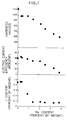
- Figure 1 is a graph showing the interrelation of iodine content, hardness and electric current efficiency versus molybdenum content in the chromium alloy plating film.
- Figure 2 is a graph showing molybdenum content in the chromium alloy plating film versus Mo/CrO 3 .
- Figure 3 is a graph showing electric current efficiency of the chromium alloy plating.
- Figure 4 is a graph showing results from the heat resistance test.
- Figure 5 is a graph showing results from the sulfuric acid corrosion resistance test.
- Figure 6 is a drawing showing an outline of the reciprocating friction testing machine.
- Figure 7 is a graph showing results from the wear test.
- Figure 8 is a longitudinal cross sectional view showing a portion of the piston ring.
- Figure 9 is a longitudinal cross sectional view showing the cylinder liner.
- the chromium alloy plating film of this invention is a Cr-Mo-I type alloy plating film containing iodine in 0.1 to 1.4 percent by weight and molybdenum in 0.4 to 3.8 percent by weight.
- the chromium alloy plating film of this invention can be obtained under the following conditions.
- IO 3 - has been added in the form of iodic acid (HIO 3 ) or iodate (KIO 3 , NaIO 3 , etc.).
- MoO 4 -- has been added in the form of molybdate (Na 2 MoO 4 ⁇ 2H 2 O, (NH 4 ) 6 Mo 7 O 24 ⁇ 4H 2 O, etc.).
- Cl - has the effect of widening the luster area of the plating, while F - has the effect of increasing the adhesion of the plating film.
- F - may be added in the form of KF, NaF, H 2 SiF 6 , or K 2 SiF 6 .
- the characteristics of the plating surface of the Cr-Mo-I type alloy plating film obtained under the conditions shown below in (A) are shown in Table 1 (crack status) and in Table 2 (plating surface luster).
- Table 1 and Table 2 reveal the following. At a plating temperature of 60°C or more, or Mo/CrO 3 of 0.16 or more, the plating has no cracks and the plating particles are fine. Also, when Mo/CrO 3 is low and the temperature is low, a luster is obtained, and when Mo/CrO 3 is high and the temperature is high, a blackish, non-lustrous appearance is obtained.
- Table 3 shows the molybdenum content, iodine content, hardness and electric current efficiency in the chromium alloy plating film obtained under the above mentioned plating conditions (A) with a plating temperature however of 40°C.
- the molybdenum content and the iodine content were measured by EPMA.
- Fig. 1 The interrelations of the hardness, electric current efficiency and iodine content versus the molybdenum content in the chromium alloy plating film in Table 3 are shown in a graph in Fig. 1.
- Fig. 1 clearly shows, the iodine content in the Cr-Mo-I type alloy plating film decreases as the molybdenum content is increased.
- the iodine content reaches a fixed value of about 0.15 percent.
- a Vickers hardness in the range of HV980 to 600 was obtained and this hardness showed a tendency to decrease as the molybdenum content is increased.
- the iodine content can be increased to 1.4 percent. Further, if the KIO 3 amount is decreased, then the iodine content can be reduced down to 0.1 percent.
- Table 4 compares the electric current efficiency of the Cr-Mo-I type alloy plating (embodiment) with that of the Cr-Mo type alloy plating (comparative example) and the values are each plotted in the graph in Fig. 3.
- the Cr-Mo-I type alloy plating of this invention has high electric current efficiency compared to the Mo-Cr type alloy plating. Further, plating can be performed even when the Mo/CrO 3 has comparatively high values.
- the Vickers hardness was next measured as plating and after heating for two hours at various temperatures in atmosphere.
- Table 5 shows the heat resistance ratings and the corresponding graph is shown in Fig.4.
- the plating film of the embodiment was an Cr-Mo-I type alloy plating film at 0.05 for the Mo/CrO 3 in Table 3.
- the comparative example A was hard chromium plating using sergent bath.
- the comparative example B was hard chromium plating using fluoride plating bath. The plating conditions for these comparative examples are listed below.
- the hardness of both the comparative example A and the comparative example B decreases to about HV500 when heated at 600°C as can be clearly seen in Fig. 4.
- the Cr-Mo-I type alloy plating of this invention maintains a high level of hardness even when heated to 600°C or more.
- the plating film used was the same as shown in Table 3.
- the resistance to sulfuric acid corrosion was tested by immersing the plated material in dilute sulfuric acid solution of 0.1% (PH1.5) at a bath temperature of 30°C and then evaluated by the corrosion amount per hour ( ⁇ m/Hr) after 2 hours and after 4 hours.
- Molybdenum content in plating film wt% Corrosion amount ⁇ m/Hr 2Hr 4Hr 0 3.5 3.2 0.30 2.5 2.5 0.40 0.7 0.8 0.89 0.8 0.7 1.37 0 0 2.07 0 0 2.50 0 0
- the resistance to sulfuric acid corrosion can be clearly seen to improve with an increase in the molybdenum content in the chromium alloy plating film as shown in Fig. 5. Extremely good resistance to sulfuric acid corrosion was obtained with a molybdenum content of 0.4 percent or more.
- the plating conditions for the embodiments A and B, and the comparative example D were set per the above mentioned plating conditions (A) such that :
- FIG. 6 shows an outline of the reciprocating friction testing machine used in the test.
- a pin-shaped upper test piece 10 is supported by a fixed block 11.
- a downward load is applied to the upper test piece 10 from above by a hydraulic cylinder 12 and the upper test piece 10 is pressed against a lower test piece 13.
- the flat base shaped lower test piece 13 is supported by a movable block 14 and moved back and forth by a crank mechanism 15.
- the numeral 16 denotes a load cell.
- Test conditions were as follows. (Break-in conditions) Load 2 kgf Reciprocating speed 100cpm Time 5 minutes (Wear conditions) Load 10 kgf Reciprocating speed 600cpm Time 60 minutes
- the amount of wear (in ⁇ m) measured on the film after testing with the reciprocating friction testing machine is shown in Table 7.
- the heat treatment in the table was the following.
- the test pieces after plating were heated for two hours at 300°C in the atmosphere and then air-cooled.
- Wear amount ⁇ m Mo wt% No Heat Treatment Heat Treatment Upper test piece Lower test piece Upper test piece Lower test piece Embodiment A 0.89 3.3 2.4 3.1 2.3 Embodiment B 2.07 3.6 2.3 3.7 2.5 Comparative Example C 0 3.8 2.5 4.3 2.7 Comparative Example D 0 4.7 2.6 6.5 3.5
- the Cr-Mo-I type alloy plating film of this invention is ideal as a covering on sliding members and corrosion resistant members.
- the film of this invention can be utilized to cover the sliding surfaces of sliding members such as composing parts (cylinder liners and piston rings, etc.) in internal combustion engines or the surfaces where resistance to corrosion is required on corrosion resistant members such as marine or ship parts.
- Fig. 8 shows a piston ring as one example of a sliding member.
- the outer circumferential surface of a piston ring 1 is covered with a Cr-Mo-I type alloy plating film 2 of this invention.
- Fig. 9 shows a cylinder liner as one example of a corrosion resistant member.
- the water jacket on the outer circumferential surface of a cylinder liner 3 in other words the portion making contact with the cooling water (sea water) is covered with the Cr-Mo-I type alloy plating film 2 of this invention.
- the above described chromium alloy plating film of this invention because of superior high heat resistance, wear resistance and corrosion resistance, can be utilized on sliding members and corrosion resistant members on which conventional hard chromium plating cannot be used. Moreover, the chromium alloy plating of this invention has the important advantage of high electric current efficiency.
Landscapes
- Chemical & Material Sciences (AREA)
- Engineering & Computer Science (AREA)
- Chemical Kinetics & Catalysis (AREA)
- Electrochemistry (AREA)
- Materials Engineering (AREA)
- Metallurgy (AREA)
- Organic Chemistry (AREA)
- Electroplating And Plating Baths Therefor (AREA)
Applications Claiming Priority (3)
| Application Number | Priority Date | Filing Date | Title |
|---|---|---|---|
| JP35215796A JP3299680B2 (ja) | 1996-12-12 | 1996-12-12 | Cr−Mo−I合金めっき皮膜および前記皮膜を有する部材 |
| JP352157/96 | 1996-12-12 | ||
| JP35215796 | 1996-12-12 |
Publications (2)
| Publication Number | Publication Date |
|---|---|
| EP0848086A1 true EP0848086A1 (de) | 1998-06-17 |
| EP0848086B1 EP0848086B1 (de) | 2001-10-24 |
Family
ID=18422175
Family Applications (1)
| Application Number | Title | Priority Date | Filing Date |
|---|---|---|---|
| EP97309748A Expired - Lifetime EP0848086B1 (de) | 1996-12-12 | 1997-12-03 | Chromlegierung-Plattierungsschicht, Plattierungsverfahren und damit beschichtetes Element |
Country Status (4)
| Country | Link |
|---|---|
| US (1) | US5945226A (de) |
| EP (1) | EP0848086B1 (de) |
| JP (1) | JP3299680B2 (de) |
| DE (1) | DE69707625T2 (de) |
Families Citing this family (1)
| Publication number | Priority date | Publication date | Assignee | Title |
|---|---|---|---|---|
| US7726273B2 (en) * | 2004-03-15 | 2010-06-01 | Federal-Mogul World Wide, Inc. | High strength steel cylinder liner for diesel engine |
Citations (2)
| Publication number | Priority date | Publication date | Assignee | Title |
|---|---|---|---|---|
| JPS4940774B1 (de) * | 1969-09-18 | 1974-11-05 | ||
| US4810336A (en) * | 1988-06-21 | 1989-03-07 | M&T Chemicals Inc. | Electroplating bath and process for depositing functional, at high efficiencies, chromium which is bright and smooth |
Family Cites Families (10)
| Publication number | Priority date | Publication date | Assignee | Title |
|---|---|---|---|---|
| JPS48102040A (de) * | 1972-03-06 | 1973-12-21 | ||
| JPS4940774A (de) * | 1972-08-23 | 1974-04-16 | ||
| JPS5333941B2 (de) * | 1972-12-28 | 1978-09-18 | ||
| US4472249A (en) * | 1981-08-24 | 1984-09-18 | M&T Chemicals Inc. | Bright chromium plating baths and process |
| JPS5976539A (ja) * | 1982-10-25 | 1984-05-01 | Nichiden Kagaku Kk | 液状物質の粉末化用基材 |
| GB8411063D0 (en) * | 1984-05-01 | 1984-06-06 | Mccormick M | Chromium electroplating |
| JPH0635837B2 (ja) * | 1985-07-26 | 1994-05-11 | マツダ株式会社 | ロ−タリピストンエンジンのロ−タハウジング |
| JPH0715158B2 (ja) * | 1985-12-06 | 1995-02-22 | マツダ株式会社 | 加工性の優れた摺接部材およびその製造方法 |
| JPH0247285A (ja) * | 1988-08-08 | 1990-02-16 | C Uyemura & Co Ltd | 高耐食性クロム‐モリブデン合金皮膜の作製方法 |
| JPH0379786A (ja) * | 1989-09-01 | 1991-04-04 | M & T Chem Inc | クロムメツキ浴 |
-
1996
- 1996-12-12 JP JP35215796A patent/JP3299680B2/ja not_active Expired - Fee Related
-
1997
- 1997-12-03 EP EP97309748A patent/EP0848086B1/de not_active Expired - Lifetime
- 1997-12-03 DE DE69707625T patent/DE69707625T2/de not_active Expired - Fee Related
- 1997-12-05 US US08/986,317 patent/US5945226A/en not_active Expired - Fee Related
Patent Citations (2)
| Publication number | Priority date | Publication date | Assignee | Title |
|---|---|---|---|---|
| JPS4940774B1 (de) * | 1969-09-18 | 1974-11-05 | ||
| US4810336A (en) * | 1988-06-21 | 1989-03-07 | M&T Chemicals Inc. | Electroplating bath and process for depositing functional, at high efficiencies, chromium which is bright and smooth |
Non-Patent Citations (1)
| Title |
|---|
| DATABASE WPI Section Ch Week 7448, Derwent World Patents Index; Class M11, AN 74-83688V, XP002060280 * |
Also Published As
| Publication number | Publication date |
|---|---|
| JPH10168593A (ja) | 1998-06-23 |
| US5945226A (en) | 1999-08-31 |
| EP0848086B1 (de) | 2001-10-24 |
| JP3299680B2 (ja) | 2002-07-08 |
| DE69707625T2 (de) | 2002-09-05 |
| DE69707625D1 (de) | 2001-11-29 |
Similar Documents
| Publication | Publication Date | Title |
|---|---|---|
| US3932228A (en) | Metal material for sliding surfaces | |
| US3896009A (en) | Aluminum alloy cylinder | |
| KR920006664B1 (ko) | 다층 미끄럼 재료 | |
| CN109047776A (zh) | 一种耐磨抗咬合复合材料、耐磨抗咬合复合板及其制备方法 | |
| CN105940127B (zh) | 滑动机构 | |
| US4553856A (en) | Bearing having nickel-tin-copper barrier layer | |
| EP0848086B1 (de) | Chromlegierung-Plattierungsschicht, Plattierungsverfahren und damit beschichtetes Element | |
| EP0841414B2 (de) | Galvanische Komposit-Chrom-Beschichtung und damit beschichtetes Gleitteil | |
| JPH0617831A (ja) | すべり軸受 | |
| US4847166A (en) | Slide parts | |
| JPS58108299A (ja) | アルミニウム合金軸受 | |
| JP3729962B2 (ja) | ピストンリングの製造方法 | |
| EP1253220A1 (de) | Gleitelement | |
| JPH0641789B2 (ja) | 摺動部材 | |
| JPH0942447A (ja) | 摺動部材の組合せ | |
| JPH07117104B2 (ja) | 組合せ摺動部材 | |
| KR100831094B1 (ko) | 고강도 내마모성 니켈계 윤활합금 | |
| JP3690512B2 (ja) | アルミ合金摺動部材と相手摺動部材の組合せ | |
| JPH06235096A (ja) | 摺動部材 | |
| JPH0127145B2 (de) | ||
| CN118019879A (zh) | 具有含有颗粒的磨损保护层的活塞环、制造方法和用途 | |
| JPH05302674A (ja) | ピストンリングとシリンダの組合せ | |
| JP2008232172A (ja) | エンジンのピストン | |
| JPH10213003A (ja) | ピストンリングとシリンダライナの組合せ構造 | |
| JP2004256913A (ja) | Cr−Mo合金めっき被膜 |
Legal Events
| Date | Code | Title | Description |
|---|---|---|---|
| PUAI | Public reference made under article 153(3) epc to a published international application that has entered the european phase |
Free format text: ORIGINAL CODE: 0009012 |
|
| AK | Designated contracting states |
Kind code of ref document: A1 Designated state(s): DE GB |
|
| AX | Request for extension of the european patent |
Free format text: AL;LT;LV;MK;RO;SI |
|
| 17P | Request for examination filed |
Effective date: 19980706 |
|
| AKX | Designation fees paid |
Free format text: DE GB |
|
| RBV | Designated contracting states (corrected) |
Designated state(s): DE GB |
|
| 17Q | First examination report despatched |
Effective date: 19990823 |
|
| GRAG | Despatch of communication of intention to grant |
Free format text: ORIGINAL CODE: EPIDOS AGRA |
|
| GRAG | Despatch of communication of intention to grant |
Free format text: ORIGINAL CODE: EPIDOS AGRA |
|
| GRAG | Despatch of communication of intention to grant |
Free format text: ORIGINAL CODE: EPIDOS AGRA |
|
| GRAH | Despatch of communication of intention to grant a patent |
Free format text: ORIGINAL CODE: EPIDOS IGRA |
|
| GRAH | Despatch of communication of intention to grant a patent |
Free format text: ORIGINAL CODE: EPIDOS IGRA |
|
| GRAA | (expected) grant |
Free format text: ORIGINAL CODE: 0009210 |
|
| AK | Designated contracting states |
Kind code of ref document: B1 Designated state(s): DE GB |
|
| REF | Corresponds to: |
Ref document number: 69707625 Country of ref document: DE Date of ref document: 20011129 |
|
| REG | Reference to a national code |
Ref country code: GB Ref legal event code: IF02 |
|
| PLBE | No opposition filed within time limit |
Free format text: ORIGINAL CODE: 0009261 |
|
| STAA | Information on the status of an ep patent application or granted ep patent |
Free format text: STATUS: NO OPPOSITION FILED WITHIN TIME LIMIT |
|
| 26N | No opposition filed | ||
| PGFP | Annual fee paid to national office [announced via postgrant information from national office to epo] |
Ref country code: GB Payment date: 20061123 Year of fee payment: 10 |
|
| PGFP | Annual fee paid to national office [announced via postgrant information from national office to epo] |
Ref country code: DE Payment date: 20061218 Year of fee payment: 10 |
|
| GBPC | Gb: european patent ceased through non-payment of renewal fee |
Effective date: 20071203 |
|
| PG25 | Lapsed in a contracting state [announced via postgrant information from national office to epo] |
Ref country code: DE Free format text: LAPSE BECAUSE OF NON-PAYMENT OF DUE FEES Effective date: 20080701 |
|
| PG25 | Lapsed in a contracting state [announced via postgrant information from national office to epo] |
Ref country code: GB Free format text: LAPSE BECAUSE OF NON-PAYMENT OF DUE FEES Effective date: 20071203 |