EP0848124A2 - Serrure avec pêne demi-tour et pêne dormant - Google Patents
Serrure avec pêne demi-tour et pêne dormant Download PDFInfo
- Publication number
- EP0848124A2 EP0848124A2 EP97118684A EP97118684A EP0848124A2 EP 0848124 A2 EP0848124 A2 EP 0848124A2 EP 97118684 A EP97118684 A EP 97118684A EP 97118684 A EP97118684 A EP 97118684A EP 0848124 A2 EP0848124 A2 EP 0848124A2
- Authority
- EP
- European Patent Office
- Prior art keywords
- nut
- lock
- arm
- lever
- bolt
- Prior art date
- Legal status (The legal status is an assumption and is not a legal conclusion. Google has not performed a legal analysis and makes no representation as to the accuracy of the status listed.)
- Granted
Links
Images






Classifications
-
- E—FIXED CONSTRUCTIONS
- E05—LOCKS; KEYS; WINDOW OR DOOR FITTINGS; SAFES
- E05B—LOCKS; ACCESSORIES THEREFOR; HANDCUFFS
- E05B59/00—Locks with latches separate from the lock-bolts or with a plurality of latches or lock-bolts
-
- E—FIXED CONSTRUCTIONS
- E05—LOCKS; KEYS; WINDOW OR DOOR FITTINGS; SAFES
- E05B—LOCKS; ACCESSORIES THEREFOR; HANDCUFFS
- E05B63/00—Locks or fastenings with special structural characteristics
- E05B63/16—Locks or fastenings with special structural characteristics with the handles on opposite sides moving independently
-
- E—FIXED CONSTRUCTIONS
- E05—LOCKS; KEYS; WINDOW OR DOOR FITTINGS; SAFES
- E05B—LOCKS; ACCESSORIES THEREFOR; HANDCUFFS
- E05B65/00—Locks or fastenings for special use
- E05B65/10—Locks or fastenings for special use for panic or emergency doors
- E05B65/1086—Locks with panic function, e.g. allowing opening from the inside without a ley even when locked from the outside
-
- E—FIXED CONSTRUCTIONS
- E05—LOCKS; KEYS; WINDOW OR DOOR FITTINGS; SAFES
- E05C—BOLTS OR FASTENING DEVICES FOR WINGS, SPECIALLY FOR DOORS OR WINDOWS
- E05C9/00—Arrangements of simultaneously actuated bolts or other securing devices at well-separated positions on the same wing
- E05C9/02—Arrangements of simultaneously actuated bolts or other securing devices at well-separated positions on the same wing with one sliding bar for fastening when moved in one direction and unfastening when moved in opposite direction; with two sliding bars moved in the same direction when fastening or unfastening
- E05C9/026—Arrangements of simultaneously actuated bolts or other securing devices at well-separated positions on the same wing with one sliding bar for fastening when moved in one direction and unfastening when moved in opposite direction; with two sliding bars moved in the same direction when fastening or unfastening comprising key-operated locks, e.g. a lock cylinder to drive auxiliary deadbolts or latch bolts
Definitions
- the invention relates to a lock with nut actuated Latch and key-operated bolt, the pre-closed Bolt together with the latch by nut actuation is retractable and the associated with the bolt Guard locking from a swivel arm-controlled lever arm is excavated.
- a castle of the type in question is known from DE-OS 24 33 322, wherein the nut is molded onto it Swivel arm trained.
- the latter owns one Lock housing protruding drive pin for the drive one lying on the outside of the lock housing Connecting rod.
- the lock can be used Trap and bolt in a panic situation Lever actuation can be opened.
- the Swiveling the nut on the one hand the drive rod in their Unlocked position moved.
- the Swivel arm a lever arm that raises the guard locking. Then the swivel arm delays the time another lever pivots, which locks the bolt concludes.
- the object of the invention is based on the object a generic lock of simpler, more compact and to specify a structure that is favorable in terms of locking technology.
- the drive rod connecting slide is on the swivel arm which in turn moves the bolt closes after the guard locking is released beforehand.
- the nut, swivel arm and lever arm can be spatially tightly packed in a stack on top of each other in the lock housing accommodate so that the lock with little Backset can be created.
- it is between Nut and lever arm mounted swivel arm with a control cam equipped, which when the Swivel arm, caused by nut rotation, a nose acted on the lever arm, pivoted and the guard locks out.
- the swivel arm driven in opposite directions to the nut rotation. Farther the control cam is forked through an incision.
- One cam tine acts on the closed one Position and the other cam tine in the pre-closed Lock position the nose of the lever arm connected with the fact that the guard locking interlock to the bar is raised. Since the latter over the slot / pin control with the connecting rod connecting slide coupled, takes place along with a displacement of the connecting rod connecting slide closing the bolt, be it in the closing position or in the closed position. To this Purpose is in the area of the control cam slot open on the edge, into which the pin of the connecting rod connecting slide engages with clutch. So serves the control cam not only for lifting the lever arm, but also contains the slot for positive driving of the connecting rod connecting slide.
- the lever arm it is the an arm of a substantially transverse to the drive rod displacement direction double lever mounted in the lock housing, whose other arm attacks the tumbler.
- the attack can be controlled by means of a tenon / slot control respectively.
- the nut split in two and / or in a sprung Held in the middle position To operate the lock independently using an inside handle as well to be able to make using an outside handle the nut split in two and / or in a sprung Held in the middle position. Then the nut or each nut half has an edge-side recess in which a radial extension of the swivel arm with play intervenes in such a way that when taking place from the inside or outside Lever pushes upward and closes with at least one-sided downward movement of the Bolts and the latch are retractable at the same time.
- the interchangeable swivel lever a partition between the polygonal openings of the two nut halves, so that the opposite Presser pins do not interfere with each other, For example, by the fact that the one press pin protrudes far beyond the nut half assigned to it and enters the other. It has a stabilizing effect taking the measure that the change pivot lever has bearing collars on both sides, which are in pan-shaped Insert recesses in the side of the nut halves. Each half of the nut is thus supported on both sides.
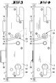
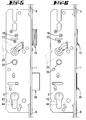
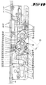
- the lock shown is as an espagnolette lock designed and has an elongated cuff 1 with attached to the lock floor 2. At a parallel distance to this is a castle ceiling 3 with unspecified Screws held. Lying on the Lock base 2 is a connecting rod connecting slide 4 led parallel to the cuff 1 and adjacent to it. The drive rod connecting slide 4 is with Driving rods 5, 6 coupled, which are flat on the Lie on the back of the cuff 1 and which are not shown, wear known locking members.
- a two-part Nut N stored in the upper area of the lock housing.
- One half of the nut 7 sits rotatable in the castle ceiling 3, while the other half of the nut 8 is rotatably received by the lock base 2, see Fig. 8.
- a change pivot lever 9 stored between the two nut halves 7, 8 is a change pivot lever 9 stored.
- the interchangeable pivot lever 9 is provided on both sides with bearing collars 11, which are in pan-shaped Recesses 12 of the side walls of the nut halves form fit. So the nut halves 7, 8 in addition to their storage in the castle floor 2 or castle ceiling 3 additional storage using the interchangeable swivel lever 9.
- the change pivot lever 9 forms a trap attack arm 13, which extends into the area of a trap tail 14 a trap 15 extends.
- a trap 15 extends in the trap tail 14
- a pin is used to fix it Cross screw 18 of the trap tail 14, which in a Ring groove of the pin 17 dips.
- This configuration allows the trap head 16 to be turned over Trap spring serving compression spring 19 acts on the Trap 14 and thus the trap 15 in the direction of advance.
- Trap spring serving compression spring 19 acts on the Trap 14 and thus the trap 15 in the direction of advance.
- One between the castle floor 2 and the castle ceiling 3 located spring housing 20 protrudes with a projection 21 in the trajectory of the trap tail 14 and thus limits the outward movement of the trap 15.
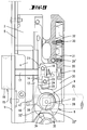
- the dovetail 14 takes the dovetail one parallel to the castle floor 2 and castle ceiling 3 relocatable driver 22. One reaches into this on the trap tail 14 set screw 23. By adjusting the same from the lock housing exterior ago it is possible that the driver 22 either with one or the other half of the nut cooperates. in the In the present case, the driver 22 extends in the Movement range of an arm 24 of the door handle 25 associated nut half 8, see Fig. 9. In this Figure is the nut half assigned to the door handle 26 7 not shown
- the nut half 7 assigned to the outside door handle 26 also has a congruent to the arm 24 Arm 27, which in the embodiment however, has no effect. Therefore it is from the Outside of door by pushing downwards not possible to withdraw the trap 15.
- Each nut half 7, 8 is approximately diametrically opposite, horizontal shoulders 28 fitted. On the two shoulders 28 each half of the nut 7, 8 each engage a spring-loaded slide 29 or 30.
- the slider 29 is the lock cover 3 turned and has an angled extension 29 ', which is acted upon by a compression spring 31 of the spring housing 20 becomes. Separately from the compression spring 31 that takes Spring housing 20 a further compression spring 32. This acts on the extension 30 'of the lock base 2 guided slide 30.
- Each half of the nut has below the polygonal opening 10 7, 8 an edge-side recess 33 into which a Radial extension 34 one stored below the nut N.
- Swivel arm 35 engages with play.
- the Swivel arm 35 is in turn in the castle floor 2 and Castle ceiling 3 rotatably mounted.
- the Radial extension 34 of the edge 33 'of the recess 33 adjacent, cf. in particular Fig. 9. be it from inside or outside therefore no take-along due to the movement play of the swivel arm 35.
- the one below the trap 15 in the castle housing Bolt 36 is a vertically rising tumbler 37 assigned.
- the latter has a locking extension 38, which in the closed bolt position in a locking recess 39 of the latch 36 dips.
- another Locking recess 40 is provided, which is in the closed position Bolt 36 with the locking extension 38 of the tumbler 37 cooperates.
- the tumbler 37 is in the reverse direction acted upon by a torsion spring 41 such that the Tumbler 37 with its lower area in a closing engagement opening 42 of the bolt tail 36 'protrudes.
- the closing engagement opening 42 serves for entry a lock bit 43 one in the lock housing used lock cylinder 44.
- the swivel arm 35 has a control cam 50 provided which one for lifting the tumbler 37 Nose 51 of a lever arm 52 is applied.
- This control cam 50 is forked through an incision 53, one cam tine 54 in the closed Position and the other cam tine 55 in the pre-closed Locking position applied to the nose 51.
- the lever arm 52 is the an arm of a substantially transverse to the drive rod displacement direction double lever mounted in the lock housing D, whose other arm 56 on the tumbler 37 attacks.
- the arm 56 has a slot 57 provided, in which a coupling pin 58 of the tumbler 37 engages.
- a lock pin 59 on the lock housing side is used.
- the bolt 36 is connected via a slot / pin control the connecting rod connecting slide 4 is motion-coupled.
- the latch 36 has an in Slit sloping towards its top 60, in which a driver pin 61 of the connecting rod connecting slide 4 dips. 7, ie in the closed position of the latch 36, is located the driver pin 61 at the lower end of the slope increasing slot 60.
- the swivel arm is in the area of its control cam 50 35 equipped with a slot 62 open at the edge, in which a pin 63 of the connecting rod connecting slide 4 engages positively.
- the outside door handle 26 becomes opposite to the normal handle operating direction pivoted in the upward direction, so the position shown in FIGS. 3 and 10.
- the edge 33 acts on it the radial extension 34 and displaces the swivel arm opposite to the nut turn.
- pivoting of the swivel arm 35 acts on its cam tines 54 the nose 51 of the lever arm 52 and pivots it counterclockwise, with the slot / pin engagement 57, 58 the tumbler 37 is raised, the locking extension 38 of the locking recess 39 of the Riegel's 36 leaves.
- the closing of the latch 36 and the relocation of the Driving rods 5, 6 in the locking position can also be made by means of the inside handle 25.
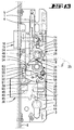
- the door handle 25 is in the upward direction 5 and 12 to pivot. It will be there taken through the door handle 25, the nut half 8, which in turn over the recess edge 33 ' the pivot arm 35 is pivoted. This acts on the nose 51 of the lever arm 52 via the cam tines 54 and pivots it while lifting it out the tumbler 37.
- the pin / slot engagement 62, 63 of the connecting rod connecting slide 4 in Moved upwards and thus over the pin / slot engagement 60, 61 the latch 36 is closed.
- the slider 30 Compression spring 32 tensioned. After releasing the inside door handle 25 brings the spring-loaded slide 30th the nut half 8 back to its neutral middle position, while the swing arm 35 in its previously occupied Position persists due to the play of movement.
- the locking and unlocking of the latch 36 is also possible by means of the lock cylinder 44, of the guard lock 43 the tumbler 37 is lifted.
- the bolt shift leads to a shift of the Espagnolette connecting slide 4 and to twist of the swivel arm 35, the radial extension 34 of which due to the play in the recess 33 moves.
Landscapes
- Engineering & Computer Science (AREA)
- Mechanical Engineering (AREA)
- Structural Engineering (AREA)
- Business, Economics & Management (AREA)
- Emergency Management (AREA)
- Lock And Its Accessories (AREA)
- Ladders (AREA)
- Holders For Apparel And Elements Relating To Apparel (AREA)
- Harvester Elements (AREA)
- Input Circuits Of Receivers And Coupling Of Receivers And Audio Equipment (AREA)
Applications Claiming Priority (2)
| Application Number | Priority Date | Filing Date | Title |
|---|---|---|---|
| DE19651609 | 1996-12-12 | ||
| DE19651609A DE19651609B4 (de) | 1996-12-12 | 1996-12-12 | Schloß mit Falle und Riegel |
Publications (3)
| Publication Number | Publication Date |
|---|---|
| EP0848124A2 true EP0848124A2 (fr) | 1998-06-17 |
| EP0848124A3 EP0848124A3 (fr) | 2000-08-09 |
| EP0848124B1 EP0848124B1 (fr) | 2002-03-20 |
Family
ID=7814426
Family Applications (1)
| Application Number | Title | Priority Date | Filing Date |
|---|---|---|---|
| EP97118684A Expired - Lifetime EP0848124B1 (fr) | 1996-12-12 | 1997-10-28 | Serrure avec pêne demi-tour et pêne dormant |
Country Status (5)
| Country | Link |
|---|---|
| EP (1) | EP0848124B1 (fr) |
| AT (1) | ATE214768T1 (fr) |
| DE (2) | DE19651609B4 (fr) |
| DK (1) | DK0848124T3 (fr) |
| ES (1) | ES2171809T3 (fr) |
Cited By (9)
| Publication number | Priority date | Publication date | Assignee | Title |
|---|---|---|---|---|
| EP1020594A3 (fr) * | 1999-01-18 | 2001-03-28 | Karl Fliether GmbH & Co. | Crémone |
| EP1106757A3 (fr) * | 1999-12-09 | 2003-01-02 | Avocet Hardware PLC | Dispositif de verrouillage à actionnement manuel |
| EP0987391A3 (fr) * | 1998-09-16 | 2003-02-05 | Carl Fuhr GmbH & Co. | Serrure à crémone avec pêne demi-tour à mode d'actuation convertible |
| EP1260660A3 (fr) * | 2001-05-23 | 2004-06-16 | Talleres De Escoriaza, S.A. | Dispositif d'actionnement d'un pêne d'une serrure |
| EP1574644A3 (fr) * | 2004-03-12 | 2009-01-21 | Carl Fuhr GmbH & Co. KG | Système de verrouillage pour portes, fenêtres ou similaires, notamment crémone-serrure avec fonction anti-panique et avec plusieurs points de condamnation |
| EP2322744A1 (fr) * | 2009-11-17 | 2011-05-18 | Glutz AG | Serrure, serrure à crochet pivotant et système de verrouillage, notamment pour le verrouillage à plusieurs points d'une porte ou d'une fenêtre |
| WO2014118015A1 (fr) * | 2013-01-30 | 2014-08-07 | Kfv Karl Fliether Gmbh & Co. Kg | Serrure anti-panique |
| WO2014118017A1 (fr) * | 2013-01-30 | 2014-08-07 | Kfv Karl Fliether Gmbh & Co. Kg | Serrure anti-panique |
| CN112242659A (zh) * | 2020-10-29 | 2021-01-19 | 国网山东省电力公司威海供电公司 | 一种10kV金属封闭式开关柜隔离挡板闭锁装置 |
Families Citing this family (1)
| Publication number | Priority date | Publication date | Assignee | Title |
|---|---|---|---|---|
| DE102009029068A1 (de) | 2009-09-01 | 2011-03-03 | Aug. Winkhaus Gmbh & Co. Kg | Schloss |
Family Cites Families (4)
| Publication number | Priority date | Publication date | Assignee | Title |
|---|---|---|---|---|
| DE2433322C3 (de) * | 1974-07-11 | 1980-06-26 | Scovill Sicherheitseinrichtungen Gmbh, 5620 Velbert | Panik-Hauptschloß mit Fallen-Nebenverschlüssen |
| ATE113108T1 (de) * | 1989-09-28 | 1994-11-15 | Schloss Und Beschlaegefabrik A | Schloss. |
| AT400062B (de) * | 1993-03-26 | 1995-09-25 | Roto Frank Eisenwaren | Mehrriegelschloss |
| ES2115191T3 (es) * | 1994-02-21 | 1998-06-16 | Hellmuller & Zingg Ag | Cerradura de puerta. |
-
1996
- 1996-12-12 DE DE19651609A patent/DE19651609B4/de not_active Expired - Fee Related
-
1997
- 1997-10-28 EP EP97118684A patent/EP0848124B1/fr not_active Expired - Lifetime
- 1997-10-28 ES ES97118684T patent/ES2171809T3/es not_active Expired - Lifetime
- 1997-10-28 AT AT97118684T patent/ATE214768T1/de not_active IP Right Cessation
- 1997-10-28 DK DK97118684T patent/DK0848124T3/da active
- 1997-10-28 DE DE59706669T patent/DE59706669D1/de not_active Expired - Lifetime
Cited By (13)
| Publication number | Priority date | Publication date | Assignee | Title |
|---|---|---|---|---|
| EP0987391A3 (fr) * | 1998-09-16 | 2003-02-05 | Carl Fuhr GmbH & Co. | Serrure à crémone avec pêne demi-tour à mode d'actuation convertible |
| EP1020594A3 (fr) * | 1999-01-18 | 2001-03-28 | Karl Fliether GmbH & Co. | Crémone |
| EP1106757A3 (fr) * | 1999-12-09 | 2003-01-02 | Avocet Hardware PLC | Dispositif de verrouillage à actionnement manuel |
| EP1260660A3 (fr) * | 2001-05-23 | 2004-06-16 | Talleres De Escoriaza, S.A. | Dispositif d'actionnement d'un pêne d'une serrure |
| EP1574644A3 (fr) * | 2004-03-12 | 2009-01-21 | Carl Fuhr GmbH & Co. KG | Système de verrouillage pour portes, fenêtres ou similaires, notamment crémone-serrure avec fonction anti-panique et avec plusieurs points de condamnation |
| EP2322744A1 (fr) * | 2009-11-17 | 2011-05-18 | Glutz AG | Serrure, serrure à crochet pivotant et système de verrouillage, notamment pour le verrouillage à plusieurs points d'une porte ou d'une fenêtre |
| WO2014118015A1 (fr) * | 2013-01-30 | 2014-08-07 | Kfv Karl Fliether Gmbh & Co. Kg | Serrure anti-panique |
| WO2014118017A1 (fr) * | 2013-01-30 | 2014-08-07 | Kfv Karl Fliether Gmbh & Co. Kg | Serrure anti-panique |
| CN104956018A (zh) * | 2013-01-30 | 2015-09-30 | Kfv卡尔弗利特有限责任两合公司 | 紧急锁 |
| CN104956018B (zh) * | 2013-01-30 | 2017-08-01 | Kfv卡尔弗利特有限责任两合公司 | 紧急锁 |
| RU2644111C2 (ru) * | 2013-01-30 | 2018-02-07 | КФВ Карл Флиетхер ГмбХ & Ко. КГ | Замок "Антипаника" |
| CN112242659A (zh) * | 2020-10-29 | 2021-01-19 | 国网山东省电力公司威海供电公司 | 一种10kV金属封闭式开关柜隔离挡板闭锁装置 |
| CN112242659B (zh) * | 2020-10-29 | 2022-07-01 | 国网山东省电力公司威海供电公司 | 一种10kV金属封闭式开关柜隔离挡板闭锁装置 |
Also Published As
| Publication number | Publication date |
|---|---|
| DE19651609A1 (de) | 1998-06-18 |
| DK0848124T3 (da) | 2002-07-15 |
| DE19651609B4 (de) | 2007-06-21 |
| EP0848124A3 (fr) | 2000-08-09 |
| ATE214768T1 (de) | 2002-04-15 |
| DE59706669D1 (de) | 2002-04-25 |
| EP0848124B1 (fr) | 2002-03-20 |
| ES2171809T3 (es) | 2002-09-16 |
Similar Documents
| Publication | Publication Date | Title |
|---|---|---|
| DE3844849C2 (de) | Treibstangenverschluß | |
| EP1932989B1 (fr) | Système de fermeture pour portes, fenêtres ou analogues, en particulier crémone-serrure à fonction d'urgence et de verrouillage à plusieurs points | |
| DE3447748C2 (fr) | ||
| EP0796968B1 (fr) | Dispositif de fermeture | |
| DE2914372C2 (de) | Von außen aufschließbares Fallen-Schubriegel-Panikschloß | |
| EP2951368A1 (fr) | Serrure anti-panique | |
| DE102004012108B4 (de) | Treibstangenschloss für Türen, Fenster oder dergleichen mit Panikfunktion und Mehrpunktverriegelung | |
| EP1557514B1 (fr) | Crémone-serrure pour porte à double battants avec fonction anti-panique | |
| EP0848124B1 (fr) | Serrure avec pêne demi-tour et pêne dormant | |
| EP0954667B1 (fr) | Serrure a pene demi-tour pour porte ou fenetre | |
| DE3631118C2 (de) | Sicherheitsschloß | |
| DE3425565A1 (de) | Treibstangenschloss | |
| EP1020597A1 (fr) | Serrure à crémone avec une serrure principal et une serrure complémentaire | |
| EP0454966B1 (fr) | Serrure avec bielle motrice actionnée par cylindre de fermeture | |
| DE4114007C2 (de) | Treibstangenverschluß | |
| EP3144455B1 (fr) | Dispositif de verrouillage | |
| DE2738746B2 (de) | Auslösevorrichtung für ein Paniktürschloß mit Falle und Riegel | |
| DE3831529C2 (de) | Treibstangenverschluß | |
| DE10058945A1 (de) | Schiebeflügelschloss | |
| EP3215696B1 (fr) | Serrure | |
| EP0974721B1 (fr) | Serrure à plusieurs pênes | |
| EP1156180B1 (fr) | Serrure avec une course de pêne étendue et avec une fonction anti-panique | |
| DE2605763C3 (de) | Treibstangenschloß mit Falle | |
| DE3706007A1 (de) | Tuerschloss | |
| DE19815671A1 (de) | Treibstangenverschluß |
Legal Events
| Date | Code | Title | Description |
|---|---|---|---|
| PUAI | Public reference made under article 153(3) epc to a published international application that has entered the european phase |
Free format text: ORIGINAL CODE: 0009012 |
|
| AK | Designated contracting states |
Kind code of ref document: A2 Designated state(s): AT BE CH DE DK ES FR GB IE IT LI LU NL |
|
| AX | Request for extension of the european patent |
Free format text: AL;LT;LV;RO;SI |
|
| PUAL | Search report despatched |
Free format text: ORIGINAL CODE: 0009013 |
|
| AK | Designated contracting states |
Kind code of ref document: A3 Designated state(s): AT BE CH DE DK ES FI FR GB GR IE IT LI LU MC NL PT SE |
|
| AX | Request for extension of the european patent |
Free format text: AL;LT;LV;RO;SI |
|
| 17P | Request for examination filed |
Effective date: 20001114 |
|
| AKX | Designation fees paid |
Free format text: AT BE CH DE DK ES FR GB IE IT LI LU NL |
|
| 17Q | First examination report despatched |
Effective date: 20010326 |
|
| GRAG | Despatch of communication of intention to grant |
Free format text: ORIGINAL CODE: EPIDOS AGRA |
|
| GRAG | Despatch of communication of intention to grant |
Free format text: ORIGINAL CODE: EPIDOS AGRA |
|
| GRAH | Despatch of communication of intention to grant a patent |
Free format text: ORIGINAL CODE: EPIDOS IGRA |
|
| GRAH | Despatch of communication of intention to grant a patent |
Free format text: ORIGINAL CODE: EPIDOS IGRA |
|
| REG | Reference to a national code |
Ref country code: GB Ref legal event code: IF02 |
|
| GRAA | (expected) grant |
Free format text: ORIGINAL CODE: 0009210 |
|
| AK | Designated contracting states |
Kind code of ref document: B1 Designated state(s): AT BE CH DE DK ES FR GB IE IT LI LU NL |
|
| REF | Corresponds to: |
Ref document number: 214768 Country of ref document: AT Date of ref document: 20020415 Kind code of ref document: T |
|
| REG | Reference to a national code |
Ref country code: CH Ref legal event code: EP |
|
| REF | Corresponds to: |
Ref document number: 59706669 Country of ref document: DE Date of ref document: 20020425 |
|
| REG | Reference to a national code |
Ref country code: CH Ref legal event code: NV Representative=s name: R. A. EGLI & CO. PATENTANWAELTE |
|
| REG | Reference to a national code |
Ref country code: DK Ref legal event code: T3 |
|
| GBT | Gb: translation of ep patent filed (gb section 77(6)(a)/1977) |
Effective date: 20020624 |
|
| ET | Fr: translation filed | ||
| REG | Reference to a national code |
Ref country code: ES Ref legal event code: FG2A Ref document number: 2171809 Country of ref document: ES Kind code of ref document: T3 |
|
| PLBE | No opposition filed within time limit |
Free format text: ORIGINAL CODE: 0009261 |
|
| STAA | Information on the status of an ep patent application or granted ep patent |
Free format text: STATUS: NO OPPOSITION FILED WITHIN TIME LIMIT |
|
| 26N | No opposition filed |
Effective date: 20021223 |
|
| PGFP | Annual fee paid to national office [announced via postgrant information from national office to epo] |
Ref country code: IE Payment date: 20051005 Year of fee payment: 9 Ref country code: FR Payment date: 20051005 Year of fee payment: 9 |
|
| PGFP | Annual fee paid to national office [announced via postgrant information from national office to epo] |
Ref country code: LU Payment date: 20051010 Year of fee payment: 9 Ref country code: DK Payment date: 20051010 Year of fee payment: 9 Ref country code: CH Payment date: 20051010 Year of fee payment: 9 |
|
| PGFP | Annual fee paid to national office [announced via postgrant information from national office to epo] |
Ref country code: BE Payment date: 20051013 Year of fee payment: 9 |
|
| PGFP | Annual fee paid to national office [announced via postgrant information from national office to epo] |
Ref country code: ES Payment date: 20051014 Year of fee payment: 9 |
|
| PG25 | Lapsed in a contracting state [announced via postgrant information from national office to epo] |
Ref country code: IE Free format text: LAPSE BECAUSE OF NON-PAYMENT OF DUE FEES Effective date: 20061030 |
|
| PG25 | Lapsed in a contracting state [announced via postgrant information from national office to epo] |
Ref country code: LI Free format text: LAPSE BECAUSE OF NON-PAYMENT OF DUE FEES Effective date: 20061031 Ref country code: DK Free format text: LAPSE BECAUSE OF NON-PAYMENT OF DUE FEES Effective date: 20061031 Ref country code: CH Free format text: LAPSE BECAUSE OF NON-PAYMENT OF DUE FEES Effective date: 20061031 |
|
| REG | Reference to a national code |
Ref country code: CH Ref legal event code: PL |
|
| REG | Reference to a national code |
Ref country code: IE Ref legal event code: MM4A |
|
| REG | Reference to a national code |
Ref country code: FR Ref legal event code: ST Effective date: 20070629 |
|
| BERE | Be: lapsed |
Owner name: KARL *FLIETHER G.M.B.H. & CO. Effective date: 20061031 |
|
| REG | Reference to a national code |
Ref country code: ES Ref legal event code: FD2A Effective date: 20061030 |
|
| PGFP | Annual fee paid to national office [announced via postgrant information from national office to epo] |
Ref country code: AT Payment date: 20071024 Year of fee payment: 11 Ref country code: IT Payment date: 20071018 Year of fee payment: 11 |
|
| PG25 | Lapsed in a contracting state [announced via postgrant information from national office to epo] |
Ref country code: FR Free format text: LAPSE BECAUSE OF NON-PAYMENT OF DUE FEES Effective date: 20061031 Ref country code: ES Free format text: LAPSE BECAUSE OF NON-PAYMENT OF DUE FEES Effective date: 20061030 |
|
| PG25 | Lapsed in a contracting state [announced via postgrant information from national office to epo] |
Ref country code: LU Free format text: LAPSE BECAUSE OF NON-PAYMENT OF DUE FEES Effective date: 20061028 |
|
| PG25 | Lapsed in a contracting state [announced via postgrant information from national office to epo] |
Ref country code: IT Free format text: LAPSE BECAUSE OF NON-PAYMENT OF DUE FEES Effective date: 20081028 Ref country code: BE Free format text: LAPSE BECAUSE OF FAILURE TO SUBMIT A TRANSLATION OF THE DESCRIPTION OR TO PAY THE FEE WITHIN THE PRESCRIBED TIME-LIMIT Effective date: 20061031 Ref country code: AT Free format text: LAPSE BECAUSE OF NON-PAYMENT OF DUE FEES Effective date: 20081028 |
|
| PGFP | Annual fee paid to national office [announced via postgrant information from national office to epo] |
Ref country code: DE Payment date: 20091029 Year of fee payment: 13 |
|
| PGFP | Annual fee paid to national office [announced via postgrant information from national office to epo] |
Ref country code: NL Payment date: 20091028 Year of fee payment: 13 |
|
| PGFP | Annual fee paid to national office [announced via postgrant information from national office to epo] |
Ref country code: GB Payment date: 20091026 Year of fee payment: 13 |
|
| REG | Reference to a national code |
Ref country code: NL Ref legal event code: V1 Effective date: 20110501 |
|
| GBPC | Gb: european patent ceased through non-payment of renewal fee |
Effective date: 20101028 |
|
| PG25 | Lapsed in a contracting state [announced via postgrant information from national office to epo] |
Ref country code: GB Free format text: LAPSE BECAUSE OF NON-PAYMENT OF DUE FEES Effective date: 20101028 Ref country code: NL Free format text: LAPSE BECAUSE OF NON-PAYMENT OF DUE FEES Effective date: 20110501 |
|
| REG | Reference to a national code |
Ref country code: DE Ref legal event code: R119 Ref document number: 59706669 Country of ref document: DE Effective date: 20110502 |
|
| PG25 | Lapsed in a contracting state [announced via postgrant information from national office to epo] |
Ref country code: DE Free format text: LAPSE BECAUSE OF NON-PAYMENT OF DUE FEES Effective date: 20110502 |