EP0848393A1 - Dispositif électrique statique - Google Patents
Dispositif électrique statique Download PDFInfo
- Publication number
- EP0848393A1 EP0848393A1 EP97810875A EP97810875A EP0848393A1 EP 0848393 A1 EP0848393 A1 EP 0848393A1 EP 97810875 A EP97810875 A EP 97810875A EP 97810875 A EP97810875 A EP 97810875A EP 0848393 A1 EP0848393 A1 EP 0848393A1
- Authority
- EP
- European Patent Office
- Prior art keywords
- winding
- radius
- disk
- disc
- windings
- Prior art date
- Legal status (The legal status is an assumption and is not a legal conclusion. Google has not performed a legal analysis and makes no representation as to the accuracy of the status listed.)
- Withdrawn
Links
- 230000003068 static effect Effects 0.000 title claims description 9
- 238000004804 winding Methods 0.000 claims description 137
- XEEYBQQBJWHFJM-UHFFFAOYSA-N Iron Chemical group [Fe] XEEYBQQBJWHFJM-UHFFFAOYSA-N 0.000 claims description 20
- 230000001681 protective effect Effects 0.000 claims description 7
- 230000005686 electrostatic field Effects 0.000 claims description 5
- 238000009413 insulation Methods 0.000 description 10
- 238000000265 homogenisation Methods 0.000 description 5
- 229910052742 iron Inorganic materials 0.000 description 5
- 239000000463 material Substances 0.000 description 4
- 239000004020 conductor Substances 0.000 description 2
- PMVSDNDAUGGCCE-TYYBGVCCSA-L Ferrous fumarate Chemical group [Fe+2].[O-]C(=O)\C=C\C([O-])=O PMVSDNDAUGGCCE-TYYBGVCCSA-L 0.000 description 1
- 230000003247 decreasing effect Effects 0.000 description 1
- 238000002955 isolation Methods 0.000 description 1
- 230000002093 peripheral effect Effects 0.000 description 1
Images
Classifications
-
- H—ELECTRICITY
- H01—ELECTRIC ELEMENTS
- H01F—MAGNETS; INDUCTANCES; TRANSFORMERS; SELECTION OF MATERIALS FOR THEIR MAGNETIC PROPERTIES
- H01F27/00—Details of transformers or inductances, in general
- H01F27/28—Coils; Windings; Conductive connections
- H01F27/2871—Pancake coils
-
- H—ELECTRICITY
- H01—ELECTRIC ELEMENTS
- H01F—MAGNETS; INDUCTANCES; TRANSFORMERS; SELECTION OF MATERIALS FOR THEIR MAGNETIC PROPERTIES
- H01F27/00—Details of transformers or inductances, in general
- H01F27/34—Special means for preventing or reducing unwanted electric or magnetic effects, e.g. no-load losses, reactive currents, harmonics, oscillations, leakage fields
- H01F27/343—Preventing or reducing surge voltages; oscillations
Definitions
- the invention relates to a static electrical device, in particular transformer, as described in the preamble of the first claim.
- a transformer with these features is, for example, from DE-43 33 185 C2 known.
- the electrostatic boundary field of windings in static electrical devices is generally three-dimensional (cylindrical spiral) and by the variable potential marked on the winding surface. So that the insulation distances between a winding and earthed components, such as an iron core or Eisenjoch, as well as to be minimized between adjacent windings, is one Homogenization of the electrostatic boundary field or a reduction in the edge field strength required. There was therefore no lack of proposals, measures to provide for targeted influencing of the peripheral field. The reduction The edge field strength of a winding arrangement has so far been among others achieved by rounding the winding edges. For that were special profiles used for the edge conductors, which are accordingly expensive and were therefore uneconomical.
- electrodes were advanced on the edge course arranged the winding, these electrodes as so-called protective or shield rings were formed with the same winding input Potential.
- protective or shield rings One application of such protective or shield rings is known from DE 32 43 595 C2. From GB 1 041 420 it is known to be electrostatic Arrange shields between adjacent windings. The stake such protective or shield rings is due to the material and in terms of cost assembly is also expensive.
- DE 43 33 185 C2 proposes control or homogenization of the electrostatic boundary field, conductive inserts between adjacent windings and between earthed components and a winding in the area of the front Winding edges.
- smaller insulation distances are used a transformer through the use of more expensive and therefore less economical Purchased materials for the lead inserts.
- the object of the invention is, in the case of a static electrical device, in particular transformer, of the type mentioned a winding arrangement to create a homogenization with simple means of the electrostatic boundary field is possible, so that a significant reduction the insulation distances and thus the overall dimensions and the total weight is achieved.
- Such a winding arrangement enables a reduction in the insulation distance between grounded components and windings and between neighboring ones Windings. As a result, smaller, more compact overall dimensions achieved with a correspondingly lower material expenditure and lower weight for Windings, insulation, the iron core and the iron yoke.
- a preferred embodiment of the invention provides that the front Edge areas of the winding step-like in the manner of a pyramid outside decreasing radial winding width by means of three discs or Disc windings are limited, the winding and the discs or Disc windings have a common mean radius. Furthermore it is advantageous here if the undervoltage winding is the iron core surrounds and the high-voltage winding coaxially the undervoltage winding encased.
- an embodiment of the invention is based on a winding arrangement shown in simplified form for a transformer.
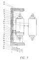
- Fig. 1 shows a winding arrangement in longitudinal section, in which an undervoltage winding 2 and a high-voltage winding 15 concentrically around one Iron core 1 are arranged. Only a section is shown. At such windings 2, 15 occur mainly in the front edge area 3, that is in the area of the windings 2, 15 facing an iron yoke 18 are to increase the strength of the electrostatic field. Here are the increases these so-called electrostatic fringe fields are particularly clear between front edge regions 3 of adjacent windings, that is between the undervoltage winding 2 and the high-voltage winding 15. So far, these electrostatic fringe fields have mainly been elaborate Isolation arrangements counteracted.
- the present inventive solution is based on the electrostatic Edge fields by means of a special design of the front To control edge regions 3 of the windings 2, 15 in such a way that there are no field strength increases here of the electrostatic field are more noticeable.
- the Homogenization of the field created in this way enables considerable Reduction of the insulation effort; especially on protective or shield rings or key inserts that are derived from the aforementioned documents of the prior art are known, can be completely dispensed with.
- a first embodiment of the invention comprises the undervoltage winding 2, which is arranged concentrically around the iron core 1 with the high-voltage winding 15 is.
- the undervoltage winding 2 has a core center 16 with one Spaced inner radius 4, and has between this inner radius 4 and one Outer radius 5 has a mean radius 6.
- the cross section of the undervoltage winding 2 is thus limited between the outer radius 6 and the inner radius 4 to a winding width 7.
- the disk winding 8 has between an outer radius 10 and an inner radius 9 a winding width 12 and their average radius 10 coincides with the average radius 6 of the undervoltage winding 2 together.
- the winding width 12 of the disk winding 8 is smaller than the winding width 7 of the undervoltage winding 2, and that for Eisenjoch 18 arranged disc windings 8 adjacent disc windings 13, 14, each also have a smaller winding width than the disk winding adjacent to the undervoltage winding 2 towards the inside.
- the arrangement of the disk windings 8, 13, 14 thus results in one pyramidal termination of the front edge regions 3 of the undervoltage winding 2nd
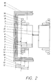
- FIG. 2 shows a further embodiment, in which the disk windings 8, 13, 14 also to the Eisenjoch 18th have a smaller winding width in stages.
- the inner radii fall, such as the inner radius 9 of the Disc winding 8, together with the inner radius 4 of the undervoltage winding 2, and the outer radii of the disk windings on the high-voltage winding 15 coincide with their outer radius.
- the invention is not limited to the exemplary embodiments shown and described.
- Another arrangement of the disk windings 8, 13, 14 is also conceivable, in which neither their inner radius nor their outer radius coincides with a geometric radius (inner radius, outer radius) of the associated undervoltage winding 2 or high-voltage winding 15.
- the types of undervoltage winding 2 and high-voltage winding 15 itself remain unspecified by the invention. In this case, the winding types that are common in practice, such as cylinder windings or layer windings, can be used.
Landscapes
- Engineering & Computer Science (AREA)
- Power Engineering (AREA)
- Insulating Of Coils (AREA)
- Coils Of Transformers For General Uses (AREA)
Applications Claiming Priority (2)
| Application Number | Priority Date | Filing Date | Title |
|---|---|---|---|
| DE1996150261 DE19650261A1 (de) | 1996-12-04 | 1996-12-04 | Statische elektrische Vorrichtung |
| DE19650261 | 1996-12-04 |
Publications (1)
| Publication Number | Publication Date |
|---|---|
| EP0848393A1 true EP0848393A1 (fr) | 1998-06-17 |
Family
ID=7813606
Family Applications (1)
| Application Number | Title | Priority Date | Filing Date |
|---|---|---|---|
| EP97810875A Withdrawn EP0848393A1 (fr) | 1996-12-04 | 1997-11-18 | Dispositif électrique statique |
Country Status (4)
| Country | Link |
|---|---|
| EP (1) | EP0848393A1 (fr) |
| BR (1) | BR9706069A (fr) |
| CA (1) | CA2216848A1 (fr) |
| DE (1) | DE19650261A1 (fr) |
Cited By (1)
| Publication number | Priority date | Publication date | Assignee | Title |
|---|---|---|---|---|
| EP4687156A1 (fr) * | 2024-07-30 | 2026-02-04 | Hitachi Energy Ltd | Agencement d'enroulement, transformateur et procédé de fabrication d'un agencement d'enroulement d'un transformateur |
Citations (6)
| Publication number | Priority date | Publication date | Assignee | Title |
|---|---|---|---|---|
| US1713214A (en) * | 1928-07-11 | 1929-05-14 | Gen Electric | Transformer |
| FR667334A (fr) * | 1928-04-13 | 1929-10-15 | Thomson Houston Comp Francaise | Perfectionnements aux bobinages des transformateurs avec ou sans fer, des bobines deréaction avec ou sans fer et en général aux bobinages traversés par des courantsalternatifs |
| GB397312A (en) * | 1931-10-06 | 1933-08-24 | Westinghouse Electric & Mfg Co | Improvements in or relating to electric transformers |
| DE950138C (de) * | 1952-02-14 | 1956-10-04 | Willem Smit U Co S Transformat | Transformatorwicklung |
| US2829354A (en) * | 1954-04-29 | 1958-04-01 | Allis Chalmers Mfg Co | Coil with end turn having increased insulation |
| CH377926A (de) * | 1958-11-21 | 1964-05-31 | Smit & Willem & Co Nv | Transformatorwicklung |
Family Cites Families (4)
| Publication number | Priority date | Publication date | Assignee | Title |
|---|---|---|---|---|
| DE1060036B (de) * | 1955-10-12 | 1959-06-25 | Gen Electric | Abgeschirmter Transformator oder Drosselspule |
| FR1377430A (fr) * | 1963-09-19 | 1964-11-06 | Materiel Electrique S W Le | Autotransformateurs avec enroulements de réglage |
| DE3243595C2 (de) * | 1982-11-25 | 1985-10-17 | Smit Transformatoren B.V., Nijmegen | Wicklungsanordnung für einen gasgekühlten Transformator |
| DE4333185C2 (de) * | 1993-09-29 | 1996-06-13 | Siemens Ag | Wicklungsanordnung |
-
1996
- 1996-12-04 DE DE1996150261 patent/DE19650261A1/de not_active Withdrawn
-
1997
- 1997-09-26 CA CA 2216848 patent/CA2216848A1/fr not_active Abandoned
- 1997-11-18 EP EP97810875A patent/EP0848393A1/fr not_active Withdrawn
- 1997-12-03 BR BR9706069A patent/BR9706069A/pt not_active Application Discontinuation
Patent Citations (6)
| Publication number | Priority date | Publication date | Assignee | Title |
|---|---|---|---|---|
| FR667334A (fr) * | 1928-04-13 | 1929-10-15 | Thomson Houston Comp Francaise | Perfectionnements aux bobinages des transformateurs avec ou sans fer, des bobines deréaction avec ou sans fer et en général aux bobinages traversés par des courantsalternatifs |
| US1713214A (en) * | 1928-07-11 | 1929-05-14 | Gen Electric | Transformer |
| GB397312A (en) * | 1931-10-06 | 1933-08-24 | Westinghouse Electric & Mfg Co | Improvements in or relating to electric transformers |
| DE950138C (de) * | 1952-02-14 | 1956-10-04 | Willem Smit U Co S Transformat | Transformatorwicklung |
| US2829354A (en) * | 1954-04-29 | 1958-04-01 | Allis Chalmers Mfg Co | Coil with end turn having increased insulation |
| CH377926A (de) * | 1958-11-21 | 1964-05-31 | Smit & Willem & Co Nv | Transformatorwicklung |
Cited By (2)
| Publication number | Priority date | Publication date | Assignee | Title |
|---|---|---|---|---|
| EP4687156A1 (fr) * | 2024-07-30 | 2026-02-04 | Hitachi Energy Ltd | Agencement d'enroulement, transformateur et procédé de fabrication d'un agencement d'enroulement d'un transformateur |
| WO2026027113A1 (fr) * | 2024-07-30 | 2026-02-05 | Hitachi Energy Ltd | Agencement d'enroulement, transformateur et procédé de fabrication d'un agencement d'enroulement d'un transformateur |
Also Published As
| Publication number | Publication date |
|---|---|
| BR9706069A (pt) | 1999-03-02 |
| DE19650261A1 (de) | 1998-06-10 |
| CA2216848A1 (fr) | 1998-06-04 |
Similar Documents
| Publication | Publication Date | Title |
|---|---|---|
| DE69120986T2 (de) | Spulenanordnung | |
| DE2037921A1 (de) | Blitzschutzeinnchtung | |
| DE3113139A1 (de) | "trockentransformator oder drosselspule mit luftkuehlung" | |
| DE1905932A1 (de) | Kapazitives Potentiometer | |
| DE1087263B (de) | Transformator | |
| EP0848393A1 (fr) | Dispositif électrique statique | |
| EP3353795B1 (fr) | Dispositif haute tension | |
| DE1091225B (de) | Isolationsanordnung zwischen aus Scheibenspulen aufgebauten Wicklungen verschiedener Spannung fuer Hochspannungstransformatoren u. dgl. | |
| DE3937588C2 (fr) | ||
| DE910806C (de) | Hochspannungsableitung fuer Hochspannungstransformatoren od. dgl. | |
| DE19612931C2 (de) | Wicklungsanordnung eines Transformators oder einer Drossel | |
| DE2652171A1 (de) | Vorschaltgeraet u.dgl. mit e- und i-foermigen kernblechen | |
| DE361873C (de) | Eisenkern fuer Induktionsspulen | |
| DE4333185C2 (de) | Wicklungsanordnung | |
| DE1180054B (de) | Verfahren zur Herstellung von zwischen zwei Isolierzylindern gleitfaehigen Winkelringen fuer Transformatoren und Drosselspulen | |
| DE2025384C3 (de) | Spannungssteuerung im stirnseitigen Endbereich von Lagenwicklungen von Transformatoren | |
| DE3047387C2 (de) | Isolierstützsäule für einen Hochspannungsbeschleuniger | |
| DE102017221593A1 (de) | Wicklungsanordnung | |
| DE2839281C2 (fr) | ||
| DE761087C (de) | Anordnung der Lagenwicklung von Hochspannungstransformatoren | |
| DE507334C (de) | Einrichtung zur Verteilung der Spannung an Anschluss- und Verbindungsstellen von Kabeln | |
| DE1162491B (de) | Kathodenstrahlroehre mit magnetischen Strahlablenkeinrichtungen und mit einer den Kathodenbereich gegen die Strahlablenkeinrichtungen abschirmenden Vorrichtung | |
| DE1513997B2 (de) | Abschirmflaeche fuer transformatoren, drosselspulen und dgl. hochspannungsgeraete | |
| DE1513962C3 (de) | Lagenwicklung in Mehrfachlagenschaltung für Transformatoren und Drosselspulen mit keilförmiger Isolation | |
| CH215753A (de) | Transformator für hohe Spannungen. |
Legal Events
| Date | Code | Title | Description |
|---|---|---|---|
| PUAI | Public reference made under article 153(3) epc to a published international application that has entered the european phase |
Free format text: ORIGINAL CODE: 0009012 |
|
| AK | Designated contracting states |
Kind code of ref document: A1 Designated state(s): AT BE CH DE DK ES FI FR GB GR IE IT LI LU MC NL PT SE |
|
| AX | Request for extension of the european patent |
Free format text: AL;LT;LV;MK;RO;SI |
|
| AKX | Designation fees paid | ||
| RBV | Designated contracting states (corrected) | ||
| STAA | Information on the status of an ep patent application or granted ep patent |
Free format text: STATUS: THE APPLICATION IS DEEMED TO BE WITHDRAWN |
|
| 18D | Application deemed to be withdrawn |
Effective date: 19981218 |