EP0848862B1 - Reseau d'antennes - Google Patents
Reseau d'antennes Download PDFInfo
- Publication number
- EP0848862B1 EP0848862B1 EP97927140A EP97927140A EP0848862B1 EP 0848862 B1 EP0848862 B1 EP 0848862B1 EP 97927140 A EP97927140 A EP 97927140A EP 97927140 A EP97927140 A EP 97927140A EP 0848862 B1 EP0848862 B1 EP 0848862B1
- Authority
- EP
- European Patent Office
- Prior art keywords
- antenna array
- radiating element
- array according
- decoupling structure
- decoupling
- Prior art date
- Legal status (The legal status is an assumption and is not a legal conclusion. Google has not performed a legal analysis and makes no representation as to the accuracy of the status listed.)
- Expired - Lifetime
Links
- 230000010287 polarization Effects 0.000 claims description 31
- 230000005540 biological transmission Effects 0.000 claims description 3
- 238000000926 separation method Methods 0.000 claims 3
- 238000003491 array Methods 0.000 description 18
- 230000009977 dual effect Effects 0.000 description 3
- 230000003071 parasitic effect Effects 0.000 description 3
- 238000010276 construction Methods 0.000 description 2
- 230000002349 favourable effect Effects 0.000 description 2
- 238000005192 partition Methods 0.000 description 2
- 230000005855 radiation Effects 0.000 description 2
- 239000000758 substrate Substances 0.000 description 2
- 238000004873 anchoring Methods 0.000 description 1
- 230000008878 coupling Effects 0.000 description 1
- 238000010168 coupling process Methods 0.000 description 1
- 238000005859 coupling reaction Methods 0.000 description 1
- 238000010586 diagram Methods 0.000 description 1
- 230000000694 effects Effects 0.000 description 1
- 238000005516 engineering process Methods 0.000 description 1
- 238000001465 metallisation Methods 0.000 description 1
- 238000010295 mobile communication Methods 0.000 description 1
- 238000007493 shaping process Methods 0.000 description 1
- 125000006850 spacer group Chemical group 0.000 description 1
Images

Classifications
-
- H—ELECTRICITY
- H01—ELECTRIC ELEMENTS
- H01Q—ANTENNAS, i.e. RADIO AERIALS
- H01Q1/00—Details of, or arrangements associated with, antennas
- H01Q1/52—Means for reducing coupling between antennas; Means for reducing coupling between an antenna and another structure
- H01Q1/521—Means for reducing coupling between antennas; Means for reducing coupling between an antenna and another structure reducing the coupling between adjacent antennas
- H01Q1/523—Means for reducing coupling between antennas; Means for reducing coupling between an antenna and another structure reducing the coupling between adjacent antennas between antennas of an array
-
- H—ELECTRICITY
- H01—ELECTRIC ELEMENTS
- H01Q—ANTENNAS, i.e. RADIO AERIALS
- H01Q21/00—Antenna arrays or systems
- H01Q21/24—Combinations of antenna units polarised in different directions for transmitting or receiving circularly and elliptically polarised waves or waves linearly polarised in any direction
- H01Q21/26—Turnstile or like antennas comprising arrangements of three or more elongated elements disposed radially and symmetrically in a horizontal plane about a common centre
Definitions
- Dual polarized antenna arrays i.e. radiator arrangements, which dipoles, slots or planar radiator elements for simultaneous reception or simultaneous emission electromagnetic waves with two orthogonal linear Polarizations that are separate and separate from each other decoupled outputs are sufficient known.
- radiator arrangements can, for example of several elements in the form of dipoles, Slits or planar emitter elements exist as they do for example from EP 0 685 900 A1 or from the prior publication "Antennas", second part, by Adolf Heilmann, Bibliographical Institute Mannheim / Vienna / Zurich, 1970 University pocket book publisher, pages 47 to 50, known are.
- This applies to omnidirectional spotlights for example with horizontal polarization the shapes of a dipole square or a dipole cross known, which is a coupling between the two systems offset by 90 ° exhibit.
- radiator modules To increase the antenna gain, it is possible to use several these radiator modules to antenna fields, so-called arrays, interconnect. It is per sending and receiving station not uncommon, ten or more radiator modules interconnect to an array.
- the spotlight modules can be arranged side by side or one below the other.
- the direction in which the emitter modules are straight or inclined should be arranged next to or below each other be referred to as the alignment of the antenna array.
- the object of the present invention is therefore a To create X-polarized antenna array, which is preferred broadband a high decoupling between the resulting Has feed systems for both polarizations.
- Decoupling device with a new type of decoupling structure is provided.
- This decoupling structure is completely different to the z.
- the invention Decoupling structure has a longitudinal extension on, in the vertical mounting direction two side by side Arrays arranged (basically also with horizontal Direction of attachment of two arrays arranged side by side) is aligned. In other words, they are already good Results with a vertically aligned X-polarized Array e.g. then achieved when between two on top of each other arranged radiator modules in the vertical direction extending longitudinal rod is provided.
- a longitudinal slot or another decoupling structure with an elongated recess or extension introduced is.
- the conductive ones cross-shaped structural elements of the decoupling structure connected at their intersection.
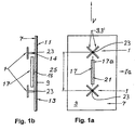
- the first is the embodiment received according to Figures 1a and 1b.
- a dipole square for example a square structure have
- the radiator modules 1 are in front of a reflector 7 Dipoles at a distance from the reflector 7 sitting on it assembled.
- the reflector 7 by a metallization 9 on a circuit board 11 formed on the back of a feed network 13th is located, which separates the individual radiator modules interconnects for the respective polarization.
- the dipoles 3 are compared via a so-called symmetrization 14 the circuit board 11 held mechanically and electrically contacted, d. H. so fed from the board 13.
- the longitudinal or extension component of the decoupling structure 17, which in the following also partially as a decoupling structural element 17 is according to the Embodiment according to Figure 1a or 1b larger than at least 1/4 of the distance between the two neighboring ones Centers or base points 23 of the radiator modules or corresponds 1/4 of this distance.
- the longitudinal component is preferably more than 40 or 50% of the said Spotlight module distance 25.
- the rod 17a shown is a short distance above the Reflector surface 7 is arranged and is a spacer 18 on the reflector 7, i.e. mechanically held by the circuit board 11 and with the reflector 7 electrically contacted.
- the decoupling structure could but also further than the double dipole arrangement 3 be removed from the reflector surface 7, wherein however then influences on the radiation diagram at good decoupling can be determined if the distance of the decoupling structure 17 from the reflector surface is more than half as far away as the dipoles the double dipole arrangement 3.
- the arrangement is preferred such that the conductive decoupling structure 17 in shape of the rod 17a not more than 1/8 to 1/4 wavelength is removed from the reflector plane.
- the arrangement can be such that the dipoles 3 'for example at a distance of 0.1 to 0.5 Wavelengths, preferably 0.2 to 0.3 wavelengths, in particular by 0.25 wavelengths, in front of the reflector surface sit, the decoupling structure in the form of the decoupling structure element 17a a distance of 0.015 up to 0.125 wavelengths, in particular 0.015 to 0.035 wavelengths (i.e. about 1/60 to 1/8, especially 1/60 to 1/30 of the wavelength), opposite the reflector surface 7 can have.
- the decoupling structure 17 is not in the form of a Rod, but in the form of a plan view of Figure 1a congruent to the rod shown there in the reflector surface 7 slot introduced.
- a conductive surface at a distance in front of the reflector surface in which a corresponding one Recess is introduced, which has a structure with a longitudinal extension, preferably parallel and in the area of the connection or mounting direction 21 lying.
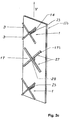
- the exemplary embodiment according to FIGS. 2a, 2b and 2c differs from the exemplary embodiment explained above in that for the decoupling structure 17 no rod extending in the connecting direction 21 17a, but a cross-shaped decoupling structural element 17b is used from two crossing bars.
- a schematic perspective illustration is shown in FIG. 2c of the embodiment shown in Figures 2a and 2b.
- the rods 27 are in this embodiment almost perpendicular to each other, the two rods almost parallel to the polarization planes, i.e. to the dipoles 3 'are aligned.
- the cruciform Decoupling structural element 17b with the rods 27 also conductive again, the two rods 27 in their intersection 29 are conductively connected.
- the longitudinal component in the connection or mounting direction 21 of the cross-shaped decoupling structure 17 thus formed 0.25 to 1 wavelength, for example, preferably 0.5 to 0.8 wavelengths, especially around 0.7 Wavelengths.
- the projection is under "longitudinal component" on the vertical, i.e. on the direct connecting line between two neighboring radiator modules in To understand the direction of cultivation. Because of the symmetrical Structure is the extension in the transverse direction to the direction of attachment 21 of the same length, but this does not have to be mandatory.
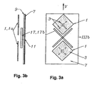
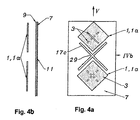
- Patch emitters 1a such as basically from the ITG technical report pre-publication 128 "antennas" (lectures of the ITG conference from April 12 to 15, 1994 in Dresden), VDE-Verlag GmbH, Berlin, Offenbach, pages 259 to 264 are known. It deals are aperture-coupled microstrip patch antennas with a cross slot or offset slot arrangement to receive two orthogonal linear Polarizations.
- the patch radiators 1a have square shapes in plan view Structure on and are with their slot arrangement each again aligned at a 45 ° angle to the vertical V in order to both + 45 ° and -45 ° polarizations received or to be able to send.
Landscapes
- Variable-Direction Aerials And Aerial Arrays (AREA)
- Aerials With Secondary Devices (AREA)
- Waveguide Aerials (AREA)
- Battery Mounting, Suspending (AREA)
Claims (17)
- Réseau d'antennes pour la réception simultanée ou l'émission simultanée d'ondes électromagnétiques avec deux polarisations linéaires orthogonales, comportant en particulier un réflecteur (7), comprenant les éléments suivants :caractérisé par les autres éléments suivants:au moins deux modules émetteurs de rayonnement (1), l'orientation du réseau d'antennes étant imposée par la direction de liaison (21) dans laquelle les modules émetteurs de rayonnement (1) sont agencés les uns à côté des autres et/ou les uns au-dessous des autres,les modules émetteurs de rayonnement (1) comprennent un agencement émetteur de rayonnement (3) pour la réception ou l'émission simultanée d'ondes électromagnétiques avec deux polarisations orthogonales,la direction de liaison (21) du réseau d'antennes est tournée par rapport à l'orientation des deux plans de polarisation orthogonaux l'un à l'autre des deux polarisations orthogonales linéaires à recevoir ou à émettre,un dispositif de découplage (17) entre deux modules émetteurs de rayonnement voisins (1),le dispositif de découplage (17) comprend une structure de découplage (17) qui s'étend par son composant longitudinal parallèlement à la direction de liaison (21) de deux modules émetteurs de rayonnement voisins (1), etle composant longitudinal de la structure de découplage respective (17) présente une longueur qui est supérieure ou égale à 25 % de la distance (25) entre les centres ou les points de pied (23) des modules émetteurs de rayonnement correspondants voisins (1).
- Réseau d'antennes selon la revendication 1, caractérisé en ce que l'extension longitudinale du composant longitudinal de la structure de découplage (17) en direction de liaison (21) est égale au moins à 50 % de la distance (25) des modules émetteurs de rayonnement.
- Réseau d'antennes selon l'une ou l'autre des revendications 1 et 2, caractérisé en ce que le rapport entre le composant longitudinal de la structure de découplage (17), mesuré dans sa direction de liaison (21), et son extension en direction de son composant transversal est supérieur à 0,5 ou égal à 0,5.
- Réseau d'antennes selon la revendication 3, caractérisé en ce que le rapport entre l'extension longitudinale en direction de liaison (21) et l'extension transversale perpendiculaire à celle-ci de la structure de découplage (17) est supérieur ou égal à 0,7 et inférieur ou égal à 1,5, de préférence supérieur ou égal à 0,9 et inférieur ou égal à 1,1, en particulier d'environ 1,0.
- Réseau d'antennes selon l'une ou l'autre des revendications 1 et 2, caractérisé en ce que la structure de découplage (17) est au moins une barre (17a) conductrice de l'électricité s'étendant par son composant longitudinal en direction de liaison (21) ou un élément allongé s'étendant sensiblement en direction de liaison (21).
- Réseau d'antennes selon l'une quelconque des revendications 1 à 5, caractérisé en ce que la structure de découplage (17) est au moins une fente (17c) qui s'étend par son composant longitudinal en direction de liaison (21) et qui est ménagée dans le réflecteur (7) ou dans une surface conductrice séparée agencée à distance en avant du réflecteur.
- Réseau d'antennes selon l'une quelconque des revendications 1 à 6, caractérisé en ce que la structure de découplage (17, 17a) est orientée du moins approximativement parallèlement à la ligne de liaison directe entre deux modules émetteurs de rayonnement voisins (1) et s'étend ici de préférence sur la ligne de liaison directe entre deux structures de découplage voisines (17, 17a).
- Réseau d'antennes selon l'une quelconque des revendications 1 à 7, caractérisé en ce que la structure de découplage (17) est constituée par un agencement en forme de croix (17b, 17c, 17d).
- Réseau d'antennes selon la revendication 8, caractérisé en ce que la structure de découplage (17) est constituée par deux ou par un multiple de deux barres (27) agencées du moins approximativement à angle droit les unes par rapport aux autres, qui sont conductrices et qui sont orientées par leur extension longitudinale respective parallèlement aux deux polarisations orientées orthogonalement l'une à l'autre.
- Réseau d'antennes selon la revendication 9, caractérisé en ce que la structure de découplage (17) est constituée par un agencement en forme de croix (17b) de barres (27b) agencées en croix les unes par rapport aux autres et parallèlement au plan du réflecteur (7), qui sont reliées de façon conductrice à leur point d'intersection (29).
- Réseau d'antennes selon la revendication 8, caractérisé en ce que l'agencement en forme de croix est constitué par un agencement de fentes (17c) en forme de croix qui est ménagé dans le réflecteur (7) ou dans une surface conductrice agencée en avant du réflecteur (7).
- Réseau d'antennes selon l'une quelconque des revendications 1 à 11, caractérisé en ce que la structure de découplage (17) est réalisée sur des plans de distances différentes vis-à-vis du réflecteur (7), la distance du plan du réflecteur étant inférieure ou égale à la moitié de la longueur d'onde des ondes électromagnétiques à recevoir ou à émettre.
- Réseau d'antennes selon l'une quelconque des revendications 1 à 12, caractérisé en ce que la structure de découplage (17) est réalisée symétriquement à la ligne de liaison directe entre deux modules émetteurs de rayonnement voisins (1) et ainsi symétriquement à la direction de liaison (21).
- Réseau d'antennes selon l'une quelconque des revendications 1 à 13, caractérisé en ce que la structure de découplage (17) est réalisée symétriquement à un plan transversal central perpendiculairement à la ligne de liaison directe entre deux modules émetteurs de rayonnement voisins (1).
- Réseau d'antennes selon l'une quelconque des revendications 8 à 14, caractérisé en ce que les deux composants situés perpendiculairement l'un à l'autre de l'agencement en forme de croix (17b, 17c, 17d) de la structure de découplage (17) sont orientés parallèlement aux deux plans de polarisation orthogonaux l'un à l'autre des deux polarisations orthogonales linéaires à recevoir ou à émettre.
- Réseau d'antennes selon l'une quelconque des revendications 1 à 15, caractérisé en ce que l'agencement émetteur de rayonnement (3) est constitué par un agencement émetteur de rayonnement dipolaire.
- Réseau d'antennes selon l'une quelconque des revendications 1 à 15, caractérisé en ce que l'agencement émetteur de rayonnement (3) est constitué par un agencement émetteur de rayonnement composite (1a).
Applications Claiming Priority (3)
| Application Number | Priority Date | Filing Date | Title |
|---|---|---|---|
| DE19627015 | 1996-07-04 | ||
| DE19627015A DE19627015C2 (de) | 1996-07-04 | 1996-07-04 | Antennenfeld |
| PCT/EP1997/002922 WO1998001923A1 (fr) | 1996-07-04 | 1997-06-05 | Reseau d'antennes |
Publications (2)
| Publication Number | Publication Date |
|---|---|
| EP0848862A1 EP0848862A1 (fr) | 1998-06-24 |
| EP0848862B1 true EP0848862B1 (fr) | 2002-04-17 |
Family
ID=7798955
Family Applications (1)
| Application Number | Title | Priority Date | Filing Date |
|---|---|---|---|
| EP97927140A Expired - Lifetime EP0848862B1 (fr) | 1996-07-04 | 1997-06-05 | Reseau d'antennes |
Country Status (7)
| Country | Link |
|---|---|
| US (1) | US6025812A (fr) |
| EP (1) | EP0848862B1 (fr) |
| KR (1) | KR100454146B1 (fr) |
| CA (1) | CA2228548C (fr) |
| DE (2) | DE19627015C2 (fr) |
| ES (1) | ES2175417T3 (fr) |
| WO (1) | WO1998001923A1 (fr) |
Cited By (1)
| Publication number | Priority date | Publication date | Assignee | Title |
|---|---|---|---|---|
| WO2022051906A1 (fr) * | 2020-09-08 | 2022-03-17 | 摩比天线技术(深圳)有限公司 | Élément de découplage et antenne |
Families Citing this family (89)
| Publication number | Priority date | Publication date | Assignee | Title |
|---|---|---|---|---|
| US5952983A (en) * | 1997-05-14 | 1999-09-14 | Andrew Corporation | High isolation dual polarized antenna system using dipole radiating elements |
| DE19823750A1 (de) * | 1998-05-27 | 1999-12-09 | Kathrein Werke Kg | Antennenarray mit mehreren vertikal übereinander angeordneten Primärstrahler-Modulen |
| DE19823749C2 (de) * | 1998-05-27 | 2002-07-11 | Kathrein Werke Kg | Dualpolarisierte Mehrbereichsantenne |
| DE19860121A1 (de) * | 1998-12-23 | 2000-07-13 | Kathrein Werke Kg | Dualpolarisierter Dipolstrahler |
| US6615026B1 (en) * | 1999-02-01 | 2003-09-02 | A. W. Technologies, Llc | Portable telephone with directional transmission antenna |
| FI990395A7 (fi) | 1999-02-24 | 2000-08-25 | Nokia Networks Oy | Laitteisto antennien keskinäisten häiriöiden vaimentamiseksi |
| US6512475B1 (en) * | 1999-04-02 | 2003-01-28 | Geophysical Survey Systems, Inc. | High-frequency dual-channel ground-penetrating impulse antenna and method of using same for identifying plastic pipes and rebar in concrete |
| DE19931907C2 (de) * | 1999-07-08 | 2001-08-09 | Kathrein Werke Kg | Antenne |
| DE69910847D1 (de) | 1999-10-26 | 2003-10-02 | Fractus Sa | Ineinandergeschachtelte mehrbandgruppenantennen |
| US6356242B1 (en) * | 2000-01-27 | 2002-03-12 | George Ploussios | Crossed bent monopole doublets |
| RU2179727C2 (ru) * | 2000-02-24 | 2002-02-20 | Институт солнечно-земной физики СО РАН | Способ измерения фазового распределения многоэлементного крестообразного интерферометра |
| DE10012809A1 (de) | 2000-03-16 | 2001-09-27 | Kathrein Werke Kg | Dualpolarisierte Dipolantenne |
| US6774745B2 (en) * | 2000-04-27 | 2004-08-10 | Bae Systems Information And Electronic Systems Integration Inc | Activation layer controlled variable impedance transmission line |
| US6452549B1 (en) | 2000-05-02 | 2002-09-17 | Bae Systems Information And Electronic Systems Integration Inc | Stacked, multi-band look-through antenna |
| AU2001257500A1 (en) * | 2000-05-02 | 2001-11-12 | Bae Systems Information And Electronic Systems Integration, Inc. | Low profile, broadband, dual mode, modified notch antenna |
| US6690331B2 (en) | 2000-05-24 | 2004-02-10 | Bae Systems Information And Electronic Systems Integration Inc | Beamforming quad meanderline loaded antenna |
| US6323814B1 (en) | 2000-05-24 | 2001-11-27 | Bae Systems Information And Electronic Systems Integration Inc | Wideband meander line loaded antenna |
| US6492953B2 (en) | 2000-05-31 | 2002-12-10 | Bae Systems Information And Electronic Systems Integration Inc. | Wideband meander line loaded antenna |
| AU2001275024A1 (en) | 2000-05-31 | 2001-12-11 | Bae Systems Information And Electronic Systems Integration, Inc. | Scanning, circularly polarized varied impedance transmission line antenna |
| AU2001276826A1 (en) | 2000-06-14 | 2001-12-24 | Bae Systems Information And Electronic Systems Integration, Inc. | Narrowband/wideband dual mode antenna |
| US6300915B1 (en) * | 2000-11-09 | 2001-10-09 | Bae Systems Aerospace Inc. Advanced Systems | Vertical array antennas for differential GPS ground stations |
| DE10064129B4 (de) * | 2000-12-21 | 2006-04-20 | Kathrein-Werke Kg | Antenne, insbesondere Mobilfunkantenne |
| KR100403764B1 (ko) * | 2000-12-28 | 2003-10-30 | 주식회사 하이닉스반도체 | 편파 다이버시티 기법 적용이 가능한 스마트 안테나 |
| FR2823017B1 (fr) * | 2001-03-29 | 2005-05-20 | Cit Alcatel | Antenne multibande de telecommunications |
| ES2287124T3 (es) * | 2001-04-16 | 2007-12-16 | Fractus, S.A. | Matriz de antenas de doble banda y doble polarizacion. |
| DE10150150B4 (de) | 2001-10-11 | 2006-10-05 | Kathrein-Werke Kg | Dualpolarisiertes Antennenarray |
| DE10203873A1 (de) * | 2002-01-31 | 2003-08-14 | Kathrein Werke Kg | Dualpolarisierte Strahleranordnung |
| US7405710B2 (en) * | 2002-03-26 | 2008-07-29 | Andrew Corporation | Multiband dual polarized adjustable beamtilt base station antenna |
| US6674406B1 (en) * | 2002-10-08 | 2004-01-06 | The United States Of America As Represented By The Secretary Of The Navy | Microstrip patch antenna with progressive slot loading |
| DE10316564B4 (de) | 2003-04-10 | 2006-03-09 | Kathrein-Werke Kg | Antenne mit zumindest einem Dipol oder einer dipolähnlichen Strahleranordnung |
| US6940465B2 (en) | 2003-05-08 | 2005-09-06 | Kathrein-Werke Kg | Dual-polarized dipole antenna element |
| US7132995B2 (en) | 2003-12-18 | 2006-11-07 | Kathrein-Werke Kg | Antenna having at least one dipole or an antenna element arrangement similar to a dipole |
| US7015871B2 (en) | 2003-12-18 | 2006-03-21 | Kathrein-Werke Kg | Mobile radio antenna arrangement for a base station |
| US7027004B2 (en) | 2003-12-18 | 2006-04-11 | Kathrein-Werke Kg | Omnidirectional broadband antenna |
| DE10359623A1 (de) * | 2003-12-18 | 2005-07-21 | Kathrein-Werke Kg | Mobilfunk-Antennenanordnung für eine Basisstation |
| DE10359622A1 (de) * | 2003-12-18 | 2005-07-21 | Kathrein-Werke Kg | Antenne mit zumindest einem Dipol oder einer dipolähnlichen Strahleranordnung |
| JP4169709B2 (ja) * | 2004-02-16 | 2008-10-22 | 株式会社国際電気通信基礎技術研究所 | アレーアンテナ装置 |
| EP1566857B1 (fr) * | 2004-02-20 | 2008-03-26 | Alcatel Lucent | Module d'antenne à double polarisation |
| DE102004025904B4 (de) | 2004-05-27 | 2007-04-05 | Kathrein-Werke Kg | Antenne |
| US7868843B2 (en) * | 2004-08-31 | 2011-01-11 | Fractus, S.A. | Slim multi-band antenna array for cellular base stations |
| US7148848B2 (en) * | 2004-10-27 | 2006-12-12 | General Motors Corporation | Dual band, bent monopole antenna |
| DE102005005781A1 (de) | 2005-02-08 | 2006-08-10 | Kathrein-Werke Kg | Radom, insbesondere für Mobilfunkantennen sowie zugehörige Mobilfunkantenne |
| KR100725501B1 (ko) * | 2005-08-19 | 2007-06-08 | 삼성전자주식회사 | 전자기파 측정장치 |
| US7616168B2 (en) * | 2005-08-26 | 2009-11-10 | Andrew Llc | Method and system for increasing the isolation characteristic of a crossed dipole pair dual polarized antenna |
| US7358924B2 (en) | 2005-10-07 | 2008-04-15 | Kathrein-Werke Kg | Feed network, and/or antenna having at least one antenna element and a feed network |
| ES2380580T3 (es) | 2005-10-14 | 2012-05-16 | Fractus S.A. | Formación menuda de antenas de triple banda para estaciones base celulares |
| DE102006037518B3 (de) * | 2006-08-10 | 2008-03-06 | Kathrein-Werke Kg | Antennenanordnung, insbesondere für eine Mobilfunk-Basisstation |
| DE102006037517A1 (de) | 2006-08-10 | 2008-02-21 | Kathrein-Werke Kg | Antennenanordnung, insbesondere für eine Mobilfunk-Basisstation |
| DE102006039279B4 (de) | 2006-08-22 | 2013-10-10 | Kathrein-Werke Kg | Dipolförmige Strahleranordnung |
| DE102007006559B3 (de) * | 2007-02-09 | 2008-09-11 | Kathrein-Werke Kg | Mobilfunkantenne, insbesondere für eine Basisstation |
| US8354972B2 (en) * | 2007-06-06 | 2013-01-15 | Fractus, S.A. | Dual-polarized radiating element, dual-band dual-polarized antenna assembly and dual-polarized antenna array |
| JP5294443B2 (ja) * | 2007-06-21 | 2013-09-18 | 三星電子株式会社 | アンテナ装置、及び無線通信端末 |
| JP5312598B2 (ja) * | 2008-09-22 | 2013-10-09 | ケーエムダブリュ・インコーポレーテッド | 移動通信基地局用二重帯域二重偏波アンテナ |
| DE102008059268A1 (de) | 2008-11-27 | 2009-11-19 | Kathrein-Werke Kg | Einrichtung zur Lageerkennung einer Antennenanordnung |
| US8838176B2 (en) * | 2012-01-10 | 2014-09-16 | Mediatek Inc. | High gain antenna and wireless device using the same |
| TWI497832B (zh) * | 2012-06-18 | 2015-08-21 | Wistron Neweb Corp | 去耦合電路及天線裝置 |
| US9437935B2 (en) | 2013-02-27 | 2016-09-06 | Microsoft Technology Licensing, Llc | Dual band antenna pair with high isolation |
| CN103715519B (zh) * | 2013-06-09 | 2016-12-28 | 京信通信技术(广州)有限公司 | 双极化阵列天线及其辐射单元 |
| DE102013012305A1 (de) | 2013-07-24 | 2015-01-29 | Kathrein-Werke Kg | Breitband-Antennenarray |
| KR101636828B1 (ko) * | 2015-01-08 | 2016-07-08 | 인하대학교 산학협력단 | 십자형 디커플러를 이용한 lte 펨토셀용 4-포트 mimo 안테나 |
| JP6610652B2 (ja) | 2015-02-16 | 2019-11-27 | 日本電気株式会社 | マルチバンドアンテナ、マルチバンドアンテナアレイ及び無線通信装置 |
| DE102015002441A1 (de) | 2015-02-26 | 2016-09-01 | Kathrein-Werke Kg | Radom sowie zugehörige Mobilfunkantenne und Verfahren zur Herstellung des Radoms oder der Mobilfunkantenne |
| US9799953B2 (en) | 2015-03-26 | 2017-10-24 | Microsoft Technology Licensing, Llc | Antenna isolation |
| DE102015007504B4 (de) | 2015-06-11 | 2019-03-28 | Kathrein Se | Dipolförmige Strahleranordnung |
| DE102015007503A1 (de) | 2015-06-11 | 2016-12-15 | Kathrein-Werke Kg | Dipolförmige Strahleranordnung |
| DE102015115892A1 (de) * | 2015-09-21 | 2017-03-23 | Kathrein-Werke Kg | Dipolsockel |
| US10833401B2 (en) * | 2015-11-25 | 2020-11-10 | Commscope Technologies Llc | Phased array antennas having decoupling units |
| DE102016104611B4 (de) | 2016-03-14 | 2020-07-09 | Telefonaktiebolaget Lm Ericsson (Publ) | Dipolförmige Strahleranordnung |
| DE102016104610A1 (de) | 2016-03-14 | 2017-09-14 | Kathrein-Werke Kg | Mehrfachhalter für eine dipolförmige Strahleranordnung und eine dipolförmige Strahleranordnung mit einem solchen Mehrfachhalter |
| ES2719213T3 (es) | 2016-03-14 | 2019-07-09 | Kathrein Se | Disposición de radiadores en forma de dipolo |
| DE102016112257A1 (de) | 2016-07-05 | 2018-01-11 | Kathrein-Werke Kg | Antennenanordnung mit zumindest einer dipolförmigen Strahleranordnung |
| DE102016219163A1 (de) | 2016-10-04 | 2018-04-05 | Bayerische Motoren Werke Aktiengesellschaft | Antennenanordnung für ein Fahrzeug und Fahrzeug |
| CN110462931B (zh) * | 2017-03-29 | 2021-07-06 | 日本电业工作株式会社 | 阵列天线以及扇形天线 |
| CN113708059B (zh) | 2017-05-16 | 2025-10-28 | 华为技术有限公司 | 一种天线 |
| DE102017116920A1 (de) | 2017-06-09 | 2018-12-13 | Kathrein Se | Dual-polarisierter Kreuzdipol und Antennenanordnung mit zwei solchen dual-polarisierten Kreuzdipolen |
| CN107546489B (zh) * | 2017-08-16 | 2020-12-15 | 京信通信技术(广州)有限公司 | 一种消除耦合谐振的多频基站天线 |
| CN111384595B (zh) * | 2018-12-29 | 2021-07-16 | 华为技术有限公司 | 多入多出天线及基站 |
| WO2020190863A1 (fr) | 2019-03-21 | 2020-09-24 | Commscope Technologies Llc | Antennes de station de base comprenant des ensembles passifs pour améliorer les performances de discrimination par polarisations croisées |
| DE102019108901A1 (de) | 2019-03-22 | 2020-09-24 | Telefonaktiebolaget Lm Ericsson (Publ) | Antennenanordnung für Mobilfunksysteme mit zumindest einem dual-polarisierten Kreuzdipol |
| CN110176671B (zh) * | 2019-05-20 | 2024-06-11 | 深圳市信维通信股份有限公司 | 一种毫米波阵列天线 |
| WO2021195040A2 (fr) | 2020-03-24 | 2021-09-30 | Commscope Technologies Llc | Antennes de station de base comprenant un module d'antenne active, dispositifs et procédés associés |
| AU2021242222A1 (en) | 2020-03-24 | 2022-11-17 | Outdoor Wireless Networks LLC | Radiating elements having angled feed stalks and base station antennas including same |
| WO2021222217A1 (fr) * | 2020-04-28 | 2021-11-04 | Commscope Technologies Llc | Antennes de station de base ayant des ensembles réflecteurs comprenant un substrat non métallique recouvert d'une couche métallique |
| CN213753057U (zh) * | 2020-12-31 | 2021-07-20 | 罗森伯格技术有限公司 | 天线振子和天线 |
| EP4040602B1 (fr) * | 2021-02-08 | 2025-03-05 | Nokia Technologies Oy | Réseau d'antennes à plaque |
| CN215418610U (zh) | 2021-08-31 | 2022-01-04 | 康普技术有限责任公司 | 频率选择反射板和基站天线 |
| CN114824793B (zh) * | 2022-04-12 | 2025-09-26 | 领翌技术(横琴)有限公司 | 解耦结构和天线阵列 |
| CN117199772A (zh) | 2022-06-01 | 2023-12-08 | 康普技术有限责任公司 | 基站天线 |
| US12469960B2 (en) | 2022-07-08 | 2025-11-11 | Outdoor Wireless Networks LLC | Base station antennas |
Family Cites Families (7)
| Publication number | Priority date | Publication date | Assignee | Title |
|---|---|---|---|---|
| US3510876A (en) * | 1967-06-29 | 1970-05-05 | Itt | Vertical beam steering antenna system |
| US3541559A (en) * | 1968-04-10 | 1970-11-17 | Westinghouse Electric Corp | Antenna for producing circular polarization over wide angles |
| DE7142601U (de) * | 1971-11-11 | 1972-07-13 | Rohde & Schwarz | Richtstrahlfeld fuer zirkulare oder elliptische polarisation zum aufbau von rundstrahlantennen |
| GB2265258B (en) * | 1992-03-11 | 1995-09-27 | Siemens Plessey Electronic | Antenna array incorporating a choke |
| DE4302905C1 (de) * | 1993-02-02 | 1994-03-17 | Kathrein Werke Kg | Richtantenne, insbesondere Dipolantenne |
| GB9410994D0 (en) * | 1994-06-01 | 1994-07-20 | Alan Dick & Company Limited | Antennae |
| SE9404312L (sv) * | 1994-12-12 | 1996-04-01 | Teracom Components Ab | Anordning vid antennsystem för att bryta högfrekventa elströmmar i den bärande konstruktionen |
-
1996
- 1996-07-04 DE DE19627015A patent/DE19627015C2/de not_active Expired - Fee Related
-
1997
- 1997-06-05 EP EP97927140A patent/EP0848862B1/fr not_active Expired - Lifetime
- 1997-06-05 CA CA002228548A patent/CA2228548C/fr not_active Expired - Fee Related
- 1997-06-05 ES ES97927140T patent/ES2175417T3/es not_active Expired - Lifetime
- 1997-06-05 KR KR10-1998-0701162A patent/KR100454146B1/ko not_active Expired - Fee Related
- 1997-06-05 WO PCT/EP1997/002922 patent/WO1998001923A1/fr not_active Ceased
- 1997-06-05 US US09/029,198 patent/US6025812A/en not_active Expired - Lifetime
- 1997-06-05 DE DE59707037T patent/DE59707037D1/de not_active Expired - Lifetime
Cited By (1)
| Publication number | Priority date | Publication date | Assignee | Title |
|---|---|---|---|---|
| WO2022051906A1 (fr) * | 2020-09-08 | 2022-03-17 | 摩比天线技术(深圳)有限公司 | Élément de découplage et antenne |
Also Published As
| Publication number | Publication date |
|---|---|
| DE19627015C2 (de) | 2000-07-13 |
| KR19990037683A (ko) | 1999-05-25 |
| EP0848862A1 (fr) | 1998-06-24 |
| US6025812A (en) | 2000-02-15 |
| ES2175417T3 (es) | 2002-11-16 |
| DE59707037D1 (de) | 2002-05-23 |
| WO1998001923A1 (fr) | 1998-01-15 |
| CA2228548C (fr) | 2003-01-14 |
| DE19627015A1 (de) | 1998-01-08 |
| CA2228548A1 (fr) | 1998-01-15 |
| KR100454146B1 (ko) | 2005-01-24 |
Similar Documents
| Publication | Publication Date | Title |
|---|---|---|
| EP0848862B1 (fr) | Reseau d'antennes | |
| EP1082782B1 (fr) | Antenne multigamme a polarisation double | |
| EP1194982B1 (fr) | Antenne | |
| EP1082781B1 (fr) | Reseau d'antennes a plusieurs modules excitateurs superposes | |
| DE10256960B3 (de) | Zweidimensionales Antennen-Array | |
| DE69901026T2 (de) | Doppelbandantenne | |
| EP1470615B1 (fr) | Ensemble antenne rayonnante a double polarisation | |
| EP1057224B1 (fr) | Antenne DIPOLE A DOUBLE POLARISATION | |
| DE69834102T2 (de) | Auf zwei isolierten kanälen arbeitende antenne | |
| EP2929589B1 (fr) | Antenne omnidirectionnelle à double polarité | |
| DE69829037T2 (de) | Antenne mit verbesserter kanaltrennung | |
| DE69938063T2 (de) | Verbesserung der polarisationstrennung | |
| EP1749331B1 (fr) | Antenne de radiotelephonie mobile a element de formation de faisceau | |
| DE69832592T2 (de) | Gerät zum empfangen und senden von funksignalen | |
| DE10012809A1 (de) | Dualpolarisierte Dipolantenne | |
| DE69828848T2 (de) | Richtantennensystem mit gekreuzter Polarisation | |
| DE69835944T2 (de) | Anordnung mit antenneneinheiten | |
| EP1525642B1 (fr) | Reseau d'antennes bidimensionnel | |
| DE602004012705T2 (de) | Dualpolarisiertes Antennenmodul | |
| DE19815003A1 (de) | Dual polarisiertes Antennenelement | |
| DE202004008770U1 (de) | Dualpolarisierte Antenne | |
| EP2514027B1 (fr) | Antenne en réseau à double polarisation, notamment antenne de téléphonie mobile | |
| DE68925005T2 (de) | Antenne mit Mikrowellenenergieverteilung über zweiseitig geschirmte Streifenleitungen. |
Legal Events
| Date | Code | Title | Description |
|---|---|---|---|
| PUAI | Public reference made under article 153(3) epc to a published international application that has entered the european phase |
Free format text: ORIGINAL CODE: 0009012 |
|
| 17P | Request for examination filed |
Effective date: 19980219 |
|
| AK | Designated contracting states |
Kind code of ref document: A1 Designated state(s): CH DE DK ES FI FR GB IE IT LI SE |
|
| 17Q | First examination report despatched |
Effective date: 20010417 |
|
| GRAG | Despatch of communication of intention to grant |
Free format text: ORIGINAL CODE: EPIDOS AGRA |
|
| REG | Reference to a national code |
Ref country code: GB Ref legal event code: IF02 |
|
| RIC1 | Information provided on ipc code assigned before grant |
Free format text: 7H 01Q 21/24 A |
|
| GRAG | Despatch of communication of intention to grant |
Free format text: ORIGINAL CODE: EPIDOS AGRA |
|
| GRAH | Despatch of communication of intention to grant a patent |
Free format text: ORIGINAL CODE: EPIDOS IGRA |
|
| GRAH | Despatch of communication of intention to grant a patent |
Free format text: ORIGINAL CODE: EPIDOS IGRA |
|
| GRAA | (expected) grant |
Free format text: ORIGINAL CODE: 0009210 |
|
| AK | Designated contracting states |
Kind code of ref document: B1 Designated state(s): CH DE DK ES FI FR GB IE IT LI SE |
|
| RIN1 | Information on inventor provided before grant (corrected) |
Inventor name: KLINGER, GEORG Inventor name: GOETTL, MAX Inventor name: GABRIEL, ROLAND |
|
| REG | Reference to a national code |
Ref country code: CH Ref legal event code: EP |
|
| GBT | Gb: translation of ep patent filed (gb section 77(6)(a)/1977) |
Effective date: 20020417 |
|
| REG | Reference to a national code |
Ref country code: IE Ref legal event code: FG4D Free format text: GERMAN |
|
| REF | Corresponds to: |
Ref document number: 59707037 Country of ref document: DE Date of ref document: 20020523 |
|
| REG | Reference to a national code |
Ref country code: CH Ref legal event code: NV Representative=s name: SCHMAUDER & PARTNER AG PATENTANWALTSBUERO |
|
| PG25 | Lapsed in a contracting state [announced via postgrant information from national office to epo] |
Ref country code: DK Free format text: LAPSE BECAUSE OF FAILURE TO SUBMIT A TRANSLATION OF THE DESCRIPTION OR TO PAY THE FEE WITHIN THE PRESCRIBED TIME-LIMIT Effective date: 20020717 |
|
| ET | Fr: translation filed | ||
| REG | Reference to a national code |
Ref country code: ES Ref legal event code: FG2A Ref document number: 2175417 Country of ref document: ES Kind code of ref document: T3 |
|
| PLBE | No opposition filed within time limit |
Free format text: ORIGINAL CODE: 0009261 |
|
| STAA | Information on the status of an ep patent application or granted ep patent |
Free format text: STATUS: NO OPPOSITION FILED WITHIN TIME LIMIT |
|
| 26N | No opposition filed |
Effective date: 20030120 |
|
| PGFP | Annual fee paid to national office [announced via postgrant information from national office to epo] |
Ref country code: FI Payment date: 20050623 Year of fee payment: 9 |
|
| PG25 | Lapsed in a contracting state [announced via postgrant information from national office to epo] |
Ref country code: FI Free format text: LAPSE BECAUSE OF NON-PAYMENT OF DUE FEES Effective date: 20060605 |
|
| REG | Reference to a national code |
Ref country code: CH Ref legal event code: PCAR Free format text: SCHMAUDER & PARTNER AG PATENT- UND MARKENANWAELTE VSP;ZWAENGIWEG 7;8038 ZUERICH (CH) |
|
| PGFP | Annual fee paid to national office [announced via postgrant information from national office to epo] |
Ref country code: IT Payment date: 20100626 Year of fee payment: 14 |
|
| PGFP | Annual fee paid to national office [announced via postgrant information from national office to epo] |
Ref country code: CH Payment date: 20100624 Year of fee payment: 14 |
|
| REG | Reference to a national code |
Ref country code: CH Ref legal event code: PL |
|
| PG25 | Lapsed in a contracting state [announced via postgrant information from national office to epo] |
Ref country code: IT Free format text: LAPSE BECAUSE OF NON-PAYMENT OF DUE FEES Effective date: 20110605 |
|
| PG25 | Lapsed in a contracting state [announced via postgrant information from national office to epo] |
Ref country code: CH Free format text: LAPSE BECAUSE OF NON-PAYMENT OF DUE FEES Effective date: 20110630 Ref country code: LI Free format text: LAPSE BECAUSE OF NON-PAYMENT OF DUE FEES Effective date: 20110630 |
|
| PGFP | Annual fee paid to national office [announced via postgrant information from national office to epo] |
Ref country code: SE Payment date: 20150623 Year of fee payment: 19 |
|
| PGFP | Annual fee paid to national office [announced via postgrant information from national office to epo] |
Ref country code: IE Payment date: 20150622 Year of fee payment: 19 |
|
| REG | Reference to a national code |
Ref country code: FR Ref legal event code: PLFP Year of fee payment: 20 |
|
| PGFP | Annual fee paid to national office [announced via postgrant information from national office to epo] |
Ref country code: DE Payment date: 20160622 Year of fee payment: 20 Ref country code: ES Payment date: 20160622 Year of fee payment: 20 Ref country code: GB Payment date: 20160628 Year of fee payment: 20 |
|
| PGFP | Annual fee paid to national office [announced via postgrant information from national office to epo] |
Ref country code: FR Payment date: 20160621 Year of fee payment: 20 |
|
| REG | Reference to a national code |
Ref country code: SE Ref legal event code: EUG |
|
| PG25 | Lapsed in a contracting state [announced via postgrant information from national office to epo] |
Ref country code: SE Free format text: LAPSE BECAUSE OF NON-PAYMENT OF DUE FEES Effective date: 20160606 |
|
| REG | Reference to a national code |
Ref country code: IE Ref legal event code: MM4A |
|
| PG25 | Lapsed in a contracting state [announced via postgrant information from national office to epo] |
Ref country code: IE Free format text: LAPSE BECAUSE OF NON-PAYMENT OF DUE FEES Effective date: 20160605 |
|
| REG | Reference to a national code |
Ref country code: DE Ref legal event code: R071 Ref document number: 59707037 Country of ref document: DE |
|
| REG | Reference to a national code |
Ref country code: GB Ref legal event code: PE20 Expiry date: 20170604 |
|
| PG25 | Lapsed in a contracting state [announced via postgrant information from national office to epo] |
Ref country code: GB Free format text: LAPSE BECAUSE OF EXPIRATION OF PROTECTION Effective date: 20170604 |
|
| REG | Reference to a national code |
Ref country code: ES Ref legal event code: FD2A Effective date: 20170926 |
|
| PG25 | Lapsed in a contracting state [announced via postgrant information from national office to epo] |
Ref country code: ES Free format text: LAPSE BECAUSE OF EXPIRATION OF PROTECTION Effective date: 20170606 |
|
| REG | Reference to a national code |
Ref country code: DE Ref legal event code: R082 Ref document number: 59707037 Country of ref document: DE Representative=s name: FLACH BAUER STAHL PATENTANWAELTE PARTNERSCHAFT, DE Ref country code: DE Ref legal event code: R081 Ref document number: 59707037 Country of ref document: DE Owner name: KATHREIN SE, DE Free format text: FORMER OWNER: KATHREIN-WERKE KG, 83022 ROSENHEIM, DE |
|
| REG | Reference to a national code |
Ref country code: GB Ref legal event code: 732E Free format text: REGISTERED BETWEEN 20190314 AND 20190320 |