EP0849041A2 - Polierverfahren - Google Patents
Polierverfahren Download PDFInfo
- Publication number
- EP0849041A2 EP0849041A2 EP97310392A EP97310392A EP0849041A2 EP 0849041 A2 EP0849041 A2 EP 0849041A2 EP 97310392 A EP97310392 A EP 97310392A EP 97310392 A EP97310392 A EP 97310392A EP 0849041 A2 EP0849041 A2 EP 0849041A2
- Authority
- EP
- European Patent Office
- Prior art keywords
- temperature
- polishing slurry
- polishing
- slurry
- maintaining
- Prior art date
- Legal status (The legal status is an assumption and is not a legal conclusion. Google has not performed a legal analysis and makes no representation as to the accuracy of the status listed.)
- Withdrawn
Links
Images


Classifications
-
- B—PERFORMING OPERATIONS; TRANSPORTING
- B24—GRINDING; POLISHING
- B24B—MACHINES, DEVICES, OR PROCESSES FOR GRINDING OR POLISHING; DRESSING OR CONDITIONING OF ABRADING SURFACES; FEEDING OF GRINDING, POLISHING, OR LAPPING AGENTS
- B24B37/00—Lapping machines or devices; Accessories
- B24B37/005—Control means for lapping machines or devices
- B24B37/015—Temperature control
-
- B—PERFORMING OPERATIONS; TRANSPORTING
- B24—GRINDING; POLISHING
- B24B—MACHINES, DEVICES, OR PROCESSES FOR GRINDING OR POLISHING; DRESSING OR CONDITIONING OF ABRADING SURFACES; FEEDING OF GRINDING, POLISHING, OR LAPPING AGENTS
- B24B55/00—Safety devices for grinding or polishing machines; Accessories fitted to grinding or polishing machines for keeping tools or parts of the machine in good working condition
- B24B55/02—Equipment for cooling the grinding surfaces, e.g. devices for feeding coolant
- B24B55/03—Equipment for cooling the grinding surfaces, e.g. devices for feeding coolant designed as a complete equipment for feeding or clarifying coolant
-
- B—PERFORMING OPERATIONS; TRANSPORTING
- B24—GRINDING; POLISHING
- B24B—MACHINES, DEVICES, OR PROCESSES FOR GRINDING OR POLISHING; DRESSING OR CONDITIONING OF ABRADING SURFACES; FEEDING OF GRINDING, POLISHING, OR LAPPING AGENTS
- B24B57/00—Devices for feeding, applying, grading or recovering grinding, polishing or lapping agents
- B24B57/02—Devices for feeding, applying, grading or recovering grinding, polishing or lapping agents for feeding of fluid, sprayed, pulverised, or liquefied grinding, polishing or lapping agents
-
- H—ELECTRICITY
- H10—SEMICONDUCTOR DEVICES; ELECTRIC SOLID-STATE DEVICES NOT OTHERWISE PROVIDED FOR
- H10P—GENERIC PROCESSES OR APPARATUS FOR THE MANUFACTURE OR TREATMENT OF DEVICES COVERED BY CLASS H10
- H10P52/00—Grinding, lapping or polishing of wafers, substrates or parts of devices
- H10P52/40—Chemomechanical polishing [CMP]
- H10P52/403—Chemomechanical polishing [CMP] of conductive or resistive materials
-
- H—ELECTRICITY
- H10—SEMICONDUCTOR DEVICES; ELECTRIC SOLID-STATE DEVICES NOT OTHERWISE PROVIDED FOR
- H10P—GENERIC PROCESSES OR APPARATUS FOR THE MANUFACTURE OR TREATMENT OF DEVICES COVERED BY CLASS H10
- H10P95/00—Generic processes or apparatus for manufacture or treatments not covered by the other groups of this subclass
- H10P95/06—Planarisation of inorganic insulating materials
- H10P95/062—Planarisation of inorganic insulating materials involving a dielectric removal step
Definitions
- This invention relates, in general, to a method for promoting the isothermal polishing of silicon wafers during chemical-mechanical polishing and, in particular to, monitoring and controlling the temperature of the siliceous chemical-mechanical silicon polishing slurry to maintain the slurry at a constant temperature during the silicon polishing process.
- planarization or flattening of integrated circuit structures in order to facilitate the processing of multi-layer integrated circuits and to improve their yield, performance, and reliability.
- all of today's high-density integrated circuit fabrication techniques make use of some method of forming planarized structures at critical points in the fabrication process.
- the polishing apparatus used to planarize a semiconductor wafer has a turntable, often referred to as a rotating platen, and a top ring that exerts a constant pressure on the turntable.
- a polishing pad - is typically attached to the upper surface of the turntable.
- the semiconductor wafer to be polished is placed on the polishing pad and clamped between the top ring and the turntable.
- the semiconductor wafer is securably fixed to the lower surface of the top ring by wax, a pad or via suction so that the semiconductor wafer can be rotated integrally with the top ring during polishing.
- a metered stream of slurry from a slurry supply is delivered to the upper surface of the polishing pad.
- the slurry is a liquid comprising chemicals and an abrasive.
- slurry chemistry generally consists of a basic solution having a pH of about 11. This alkaline polishing slurry may also contain fine polishing particles such as colloidal silica (SiO 2 ).
- the present invention disclosed herein comprises promoting the isothermal polishing of silicon wafers during chemical-mechanical polishing by monitoring and controlling the temperature of the siliceous chemical-mechanical silicon polishing slurry to maintain the slurry at a constant temperature during the silicon polishing process.
- the method provides for recycling and reusing the polishing slurry so that the polishing slurry is not discarded after each production cycle.
- the method of the present invention comprises recirculating a polish slurry in a chemical-mechanical wafer polishing apparatus and monitoring the temperature of the polishing slurry at one or more points in the recirculation process.
- the slurry temperature is maintained by exposing the polishing slurry to either heating or cooling elements or both.
- the mechanism that determines the relative heating and cooling effect on the polishing slurry responds to the input temperature from the temperature probe or probes disposed to read slurry temperature.
- the location of a temperature probe may depend on the desired input that serves to control the heating and cooling elements.
- the temperature control mechanism may be via a direct connection between the temperature probe or probes and the heating and cooling elements.
- a controller may be disposed between the temperature probe or probes to control the relative heating and cooling of the polish slurry.
- the controller is responsive to a user-defined input, for example, a specific temperature or temperature range for the polish slurry.
- a temperature probe may be located at the beginning and at the end of the slurry recirculation cycle.
- the slurry temperature may be measured with an in-line temperature probe installed as close as possible to the heating and cooling elements, since the polishing slurry will dissipate heat by convection to the environmental air and to the recirculation plumbing.
- the exit temperature of the slurry from the heating and cooling elements may also be measured to ensure optimum slurry temperature is maintained.
- the present invention helps semiconductor wafer producers to limit the number of variables that affect wafer quality and yield, by allowing the polishing unit operator to closely monitor and control the polishing slurry temperature throughout the polishing process. For example, the controller may want to maintain slurry temperature constant throughout the polishing run. Alternatively, the operator may want to rapidly or slowly ramp slurry temperature either up or down during the polishing process to address changes in slurry pH, composition, or because the wafer being polished has special temperature and friction requirements.
- An alternative to the ramping method is using the present invention to control the polishing slurry temperature in discrete steps at different stages of the polishing process.
- the operator may also want to vary temperature according to the number of times that a polishing slurry has already been used.
- the operator may want to vary the temperature depending on the dilution, if any, of the polishing slurry.
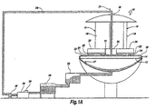
- FIG. 1A a typical apparatus for chemical-mechanical polishing of various workpieces, such as semiconductor wafers, is generally depicted as 10.
- the polishing apparatus 10 includes a lower platen 12 having a polishing pad 14 attached thereto on the upper surface of the lower platen 12.
- the polishing apparatus 10 may include a plurality of polishing units 16.
- Each polishing unit 16 includes a shaft 18, an upper platen 20, and a carrier plate 22.
- Each polishing unit 16 holds at least one semiconductor wafer 24.
- the lower platen 12 and the polishing unit 16 are counter rotated such that the lower surface of the semiconductor wafers 24 contacts the upper surface of the polishing pad 14.
- the polishing units 16 are rotated by the friction generated between the polished surface of semiconductor wafers 24 and polishing pad 14.
- the lower platen 12 and the upper platens 20 both rotate counterclockwise while the center drive 26 rotates clockwise while evenly distributed slurry 28 across polishing pad 14 through a circular gap between center drive 26 and polishing pad 14.
- the slurry 28 provides for both chemical and mechanical polishing of the silicon wafers 24.
- the temperature of the polishing slurry 28 is varied in a temperature control chamber 36.
- the necessity for, and the amount of, cooling and heating of the slurry 28 in the temperature control chamber 36 may be determined from slurry temperature samples taken at one or more strategic locations throughout the circulation path of the slurry 28. For example, the temperature may be tested proximate to the center drive 26 at point 31, in the defoaming chamber 32 or upstream of the temperature control chamber 36 by temperature probes 37 or 41.
- a pump 38 circulates the slurry 28 back to the surface of the polishing pad 14.
- the temperature controller chamber 36 receives the input from one or more temperature probes 35, 37 or 41 located to sample slurry temperature. Slurry temperature may be samples in intervals, or may be monitored continuously. The output from the probes 35, 37 and 41 may be directed to a controller 39 on the temperature controlled chamber 36, that may also be used by the operator to preset the inlet slurry temperature during a polishing run. In operation, a user-defined temperature is set before the polishing run to, for example, pre-heat the slurry. The temperature set by the operator may also vary throughout the polishing run between about 17 and 70 degrees Celsius, depending on the specific needs of the wafer.
- FIG. 1B shows an alternative placement for the temperature control chamber 36.
- the temperature control chamber 36 is located in the slurry 28 recirculation path at a point downstream of the pump 38. Temperature control chamber 36 controls the temperature of the slurry 28 during the polishing process. Temperature measurements of the slurry 28 may be taken in a variety of locations such as at point 29, 31 or 33. Similarly, temperature measurements from a variety of locations may be automatically relayed to controller 39 of temperature control chamber 36 from probes 35, 37 or 41.
- temperature control chamber 36 the location, number, and method of temperature measurement is not critical to the present invention, so long as accurate slurry 28 temperature measurements are provided to temperature control chamber 36, such that the slurry 28 temperature is adequately controlled in the temperature control chamber 36.
- Figure 2 shows one embodiment of the temperature control chamber 36.
- a slurry chiller 40 is located in parallel with a slurry heater 42.
- the slurry chiller 40 and the slurry heater 42 may each be shell and tube heat exchangers.
- the slurry 28 does not come in contact with the cooling or heat medium.
- the slurry chiller 40 may be a serpentine chiller that comes in contact with the slurry 28.
- the slurry heater 42 may also be a serpentine heater that is disposed alongside or within the serpentine chiller, wherein slurry 28 comes in contact with the element of the slurry chiller 40 and the element of the slurry heater 42 almost concurrently.
- the temperature control solenoids 46 are controlled by a temperature sensing unit 44.
- Those of skill in the art will recognize that alternative embodiments of the present invention can locate the temperature sensing unit 44 either before or after the temperature control chamber 36. In fact, more than one temperature sensing unit 44 may be used to control the temperature controlled solenoids 46.
- the temperature controlled solenoids 46 may be placed before or after the slurry chiller 40 and the slurry heater 42.
- a mixing chamber 48 may be located downstream of the slurry chiller 40 and the slurry heater 42 to allow the slurry 28 to reach a uniform temperature prior to recirculation.
- the slurry chiller 40 and the slurry heater 42 may be located in series.
- one temperature controlled solenoid 46 is required to control slurry 28 flow.
- the temperature controlled solenoid 46 can be either before or after the slurry chiller 40 and slurry heater 42.
- the slurry chiller 40 and the slurry heater 42 can even form part of a single unit.
- the serpentine chiller 40 can be intertwined with either a serpentine heater 42, or by locating a heater 42 alongside the chiller 40.
- the present invention improves existing temperature control systems used during chemical-mechanical processing.
- the temperature of the wafer rises because the mechanical heat production caused by friction. Most of the heat is removed during the recirculating of slurry 28 through the recirculation system.
- the temperature of the polishing pad 14 is usually monitored and used to adjust polishing pressure and slurry flow.
- the use of the temperature control chamber 36 of the present invention to control and maintain the slurry 28 temperature directly addresses the microscale changes in wafer temperature.
- the use of the temperature control chamber 36 of the present invention minimizes or removes the temperature variable from the wafer polishing process. For example, maintaining a constant temperature will allow a more constant silicon polish rate which, in turn, improves surface quality.
- the temperature control chamber 36 of the present invention controls the temperature of the polishing slurry 28, the control of the silica to alkali ratio which prevents coagulation, settling out, gelling and precipitation of slurry components is more readily controllable.
- the use of the temperature control chamber 36 of the present invention minimizes the need to fluctuate the polishing slurry 28 flow rate which, in turn, minimizes fluctuations in polishing rate, surface quality and yield.
- the present invention therefore, synergistically improves the surface quality and yield of the chemical-mechanical polishing of silicon wafers.
- the use of the temperature control chamber 36 of the present invention to control slurry temperature also enhances the precision of the control over slurry pH and slurry flow rate.
Landscapes
- Engineering & Computer Science (AREA)
- Mechanical Engineering (AREA)
- Mechanical Treatment Of Semiconductor (AREA)
- Finish Polishing, Edge Sharpening, And Grinding By Specific Grinding Devices (AREA)
- Grinding-Machine Dressing And Accessory Apparatuses (AREA)
Applications Claiming Priority (2)
| Application Number | Priority Date | Filing Date | Title |
|---|---|---|---|
| US3367896P | 1996-12-19 | 1996-12-19 | |
| US33678P | 1996-12-19 |
Publications (2)
| Publication Number | Publication Date |
|---|---|
| EP0849041A2 true EP0849041A2 (de) | 1998-06-24 |
| EP0849041A3 EP0849041A3 (de) | 2000-02-23 |
Family
ID=21871801
Family Applications (1)
| Application Number | Title | Priority Date | Filing Date |
|---|---|---|---|
| EP97310392A Withdrawn EP0849041A3 (de) | 1996-12-19 | 1997-12-19 | Polierverfahren |
Country Status (4)
| Country | Link |
|---|---|
| EP (1) | EP0849041A3 (de) |
| JP (1) | JPH10199841A (de) |
| KR (1) | KR19980064180A (de) |
| TW (1) | TW400265B (de) |
Cited By (4)
| Publication number | Priority date | Publication date | Assignee | Title |
|---|---|---|---|---|
| EP1052060A3 (de) * | 1999-05-03 | 2001-04-18 | Applied Materials, Inc. | Verfahren zum chemisch-mechanischen Planarisieren |
| EP1175964A3 (de) * | 2000-07-27 | 2003-07-23 | Agere Systems Guardian Corporation | Sytem zum Steuern der Temperatur der Oberfläche bei dem Polieren in einer chemisch-mechanischen Planschleifvorrichtung |
| US6679769B2 (en) | 2000-09-19 | 2004-01-20 | Rodel Holdings, Inc | Polishing pad having an advantageous micro-texture and methods relating thereto |
| CN109822428A (zh) * | 2019-03-29 | 2019-05-31 | 湖南科技大学 | 主动控制剪切作用与温度诱导梯度增稠抛光加工装置 |
Families Citing this family (5)
| Publication number | Priority date | Publication date | Assignee | Title |
|---|---|---|---|---|
| JP4502168B2 (ja) * | 2001-07-06 | 2010-07-14 | ルネサスエレクトロニクス株式会社 | 化学機械研磨装置および化学機械研磨方法 |
| KR100840655B1 (ko) * | 2006-12-29 | 2008-06-24 | 동부일렉트로닉스 주식회사 | 화학기계적 연마장치 |
| CN102303281A (zh) * | 2011-09-16 | 2012-01-04 | 北京通美晶体技术有限公司 | 一种减少晶片表面缺陷的方法 |
| JP6007553B2 (ja) * | 2012-04-06 | 2016-10-12 | 信越半導体株式会社 | ウエーハの研磨方法 |
| JP7059117B2 (ja) * | 2017-10-31 | 2022-04-25 | 株式会社荏原製作所 | 研磨パッドの研磨面の温度を調整するための熱交換器、該熱交換器を備えた研磨装置、該熱交換器を用いた基板の研磨方法、および研磨パッドの研磨面の温度を調整するためのプログラムを記録したコンピュータ読み取り可能な記録媒体 |
Family Cites Families (3)
| Publication number | Priority date | Publication date | Assignee | Title |
|---|---|---|---|---|
| AU637087B2 (en) * | 1989-03-24 | 1993-05-20 | Sumitomo Electric Industries, Ltd. | Apparatus for grinding semiconductor wafer |
| US5478435A (en) * | 1994-12-16 | 1995-12-26 | National Semiconductor Corp. | Point of use slurry dispensing system |
| US5664990A (en) * | 1996-07-29 | 1997-09-09 | Integrated Process Equipment Corp. | Slurry recycling in CMP apparatus |
-
1997
- 1997-12-16 KR KR1019970069161A patent/KR19980064180A/ko not_active Withdrawn
- 1997-12-19 JP JP35171697A patent/JPH10199841A/ja active Pending
- 1997-12-19 EP EP97310392A patent/EP0849041A3/de not_active Withdrawn
-
1998
- 1998-02-06 TW TW086119254A patent/TW400265B/zh not_active IP Right Cessation
Cited By (5)
| Publication number | Priority date | Publication date | Assignee | Title |
|---|---|---|---|---|
| EP1052060A3 (de) * | 1999-05-03 | 2001-04-18 | Applied Materials, Inc. | Verfahren zum chemisch-mechanischen Planarisieren |
| EP1175964A3 (de) * | 2000-07-27 | 2003-07-23 | Agere Systems Guardian Corporation | Sytem zum Steuern der Temperatur der Oberfläche bei dem Polieren in einer chemisch-mechanischen Planschleifvorrichtung |
| US6679769B2 (en) | 2000-09-19 | 2004-01-20 | Rodel Holdings, Inc | Polishing pad having an advantageous micro-texture and methods relating thereto |
| CN109822428A (zh) * | 2019-03-29 | 2019-05-31 | 湖南科技大学 | 主动控制剪切作用与温度诱导梯度增稠抛光加工装置 |
| CN109822428B (zh) * | 2019-03-29 | 2024-05-14 | 湖南科技大学 | 主动控制剪切作用与温度诱导梯度增稠抛光加工装置 |
Also Published As
| Publication number | Publication date |
|---|---|
| JPH10199841A (ja) | 1998-07-31 |
| KR19980064180A (ko) | 1998-10-07 |
| EP0849041A3 (de) | 2000-02-23 |
| TW400265B (en) | 2000-08-01 |
Similar Documents
| Publication | Publication Date | Title |
|---|---|---|
| US6533647B1 (en) | Method for controlling a selected temperature of a planarizing surface of a polish pad. | |
| US8172641B2 (en) | CMP by controlling polish temperature | |
| KR100701356B1 (ko) | Cmp 공정 최적화 방법 | |
| US9969046B2 (en) | Method and apparatus for polishing a substrate | |
| US5679063A (en) | Polishing apparatus | |
| Malik et al. | Manufacturability of the CMP process | |
| KR980011959A (ko) | 연마대를 갖춘 화학 기계적 연마(cmp) 장치 및 그 장치내의 슬러리 재순환 방법 | |
| CN101722469A (zh) | 对晶圆进行化学机械研磨工艺的方法 | |
| EP0849041A2 (de) | Polierverfahren | |
| US6572445B2 (en) | Multizone slurry delivery for chemical mechanical polishing tool | |
| US6287192B1 (en) | Slurry supply system for chemical mechanical polishing process having sonic wave generator | |
| US6402597B1 (en) | Polishing apparatus and method | |
| US6028006A (en) | Method for maintaining the buffer capacity of siliceous chemical-mechanical silicon polishing slurries | |
| KR20010071353A (ko) | 2중 cmp 패드 조절기 | |
| Bibby et al. | CMP CoO reduction: slurry reprocessing | |
| EP0849040A2 (de) | Polierverfahren | |
| US6294472B1 (en) | Dual slurry particle sizes for reducing microscratching of wafers | |
| US6514863B1 (en) | Method and apparatus for slurry distribution profile control in chemical-mechanical planarization | |
| JP2004363229A (ja) | 半導体ウェハの研磨装置および研磨方法 | |
| JP7797424B2 (ja) | 研磨パッド温度制御による半導体基板研磨 | |
| US6849547B2 (en) | Apparatus and process for polishing a workpiece | |
| JP3374506B2 (ja) | 基体の平坦化方法 | |
| CN113070812A (zh) | 可调温的抛光液输送装置和化学机械抛光设备 | |
| EP0849778A2 (de) | Verbesserung zum Polieren eines Wafers | |
| JP2025146233A (ja) | Cmp装置およびその研磨温度制御方法 |
Legal Events
| Date | Code | Title | Description |
|---|---|---|---|
| PUAI | Public reference made under article 153(3) epc to a published international application that has entered the european phase |
Free format text: ORIGINAL CODE: 0009012 |
|
| AK | Designated contracting states |
Kind code of ref document: A2 Designated state(s): DE FR GB IT NL |
|
| AX | Request for extension of the european patent |
Free format text: AL;LT;LV;MK;RO;SI |
|
| PUAL | Search report despatched |
Free format text: ORIGINAL CODE: 0009013 |
|
| AK | Designated contracting states |
Kind code of ref document: A3 Designated state(s): AT BE CH DE DK ES FI FR GB GR IE IT LI LU MC NL PT SE |
|
| AX | Request for extension of the european patent |
Free format text: AL;LT;LV;MK;RO;SI |
|
| RIC1 | Information provided on ipc code assigned before grant |
Free format text: 7B 24B 37/04 A, 7H 01L 21/304 B, 7B 24B 49/14 B, 7B 24B 55/02 B, 7B 24B 57/02 B |
|
| 17P | Request for examination filed |
Effective date: 20000807 |
|
| AKX | Designation fees paid |
Free format text: DE FR GB IT NL |
|
| 17Q | First examination report despatched |
Effective date: 20010709 |
|
| STAA | Information on the status of an ep patent application or granted ep patent |
Free format text: STATUS: THE APPLICATION IS DEEMED TO BE WITHDRAWN |
|
| 18D | Application deemed to be withdrawn |
Effective date: 20020122 |