EP0849496B1 - Structure amortissant les vibrations - Google Patents
Structure amortissant les vibrations Download PDFInfo
- Publication number
- EP0849496B1 EP0849496B1 EP97202788A EP97202788A EP0849496B1 EP 0849496 B1 EP0849496 B1 EP 0849496B1 EP 97202788 A EP97202788 A EP 97202788A EP 97202788 A EP97202788 A EP 97202788A EP 0849496 B1 EP0849496 B1 EP 0849496B1
- Authority
- EP
- European Patent Office
- Prior art keywords
- oil
- spring
- rod
- base
- vertical
- Prior art date
- Legal status (The legal status is an assumption and is not a legal conclusion. Google has not performed a legal analysis and makes no representation as to the accuracy of the status listed.)
- Expired - Lifetime
Links
- 238000010276 construction Methods 0.000 description 8
- 230000007246 mechanism Effects 0.000 description 6
- 230000009471 action Effects 0.000 description 4
- NJPPVKZQTLUDBO-UHFFFAOYSA-N novaluron Chemical compound C1=C(Cl)C(OC(F)(F)C(OC(F)(F)F)F)=CC=C1NC(=O)NC(=O)C1=C(F)C=CC=C1F NJPPVKZQTLUDBO-UHFFFAOYSA-N 0.000 description 3
- 238000002485 combustion reaction Methods 0.000 description 2
- 239000006096 absorbing agent Substances 0.000 description 1
- 230000005540 biological transmission Effects 0.000 description 1
- 230000008859 change Effects 0.000 description 1
- 230000006835 compression Effects 0.000 description 1
- 238000007906 compression Methods 0.000 description 1
- 238000013016 damping Methods 0.000 description 1
- 230000007547 defect Effects 0.000 description 1
- 230000000694 effects Effects 0.000 description 1
- 230000001747 exhibiting effect Effects 0.000 description 1
- 230000004048 modification Effects 0.000 description 1
- 238000012986 modification Methods 0.000 description 1
Images



Classifications
-
- B—PERFORMING OPERATIONS; TRANSPORTING
- B60—VEHICLES IN GENERAL
- B60N—SEATS SPECIALLY ADAPTED FOR VEHICLES; VEHICLE PASSENGER ACCOMMODATION NOT OTHERWISE PROVIDED FOR
- B60N2/00—Seats specially adapted for vehicles; Arrangement or mounting of seats in vehicles
- B60N2/50—Seat suspension devices
- B60N2/52—Seat suspension devices using fluid means
- B60N2/522—Seat suspension devices using fluid means characterised by dampening means
-
- B—PERFORMING OPERATIONS; TRANSPORTING
- B60—VEHICLES IN GENERAL
- B60N—SEATS SPECIALLY ADAPTED FOR VEHICLES; VEHICLE PASSENGER ACCOMMODATION NOT OTHERWISE PROVIDED FOR
- B60N2/00—Seats specially adapted for vehicles; Arrangement or mounting of seats in vehicles
- B60N2/50—Seat suspension devices
- B60N2/52—Seat suspension devices using fluid means
- B60N2/527—Seat suspension devices using fluid means using liquids
-
- B—PERFORMING OPERATIONS; TRANSPORTING
- B60—VEHICLES IN GENERAL
- B60N—SEATS SPECIALLY ADAPTED FOR VEHICLES; VEHICLE PASSENGER ACCOMMODATION NOT OTHERWISE PROVIDED FOR
- B60N2/00—Seats specially adapted for vehicles; Arrangement or mounting of seats in vehicles
- B60N2/50—Seat suspension devices
- B60N2/54—Seat suspension devices using mechanical springs
- B60N2/544—Compression or tension springs
-
- B—PERFORMING OPERATIONS; TRANSPORTING
- B66—HOISTING; LIFTING; HAULING
- B66F—HOISTING, LIFTING, HAULING OR PUSHING, NOT OTHERWISE PROVIDED FOR, e.g. DEVICES WHICH APPLY A LIFTING OR PUSHING FORCE DIRECTLY TO THE SURFACE OF A LOAD
- B66F9/00—Devices for lifting or lowering bulky or heavy goods for loading or unloading purposes
- B66F9/06—Devices for lifting or lowering bulky or heavy goods for loading or unloading purposes movable, with their loads, on wheels or the like, e.g. fork-lift trucks
- B66F9/075—Constructional features or details
- B66F9/0759—Details of operating station, e.g. seats, levers, operator platforms, cabin suspension
-
- F—MECHANICAL ENGINEERING; LIGHTING; HEATING; WEAPONS; BLASTING
- F16—ENGINEERING ELEMENTS AND UNITS; GENERAL MEASURES FOR PRODUCING AND MAINTAINING EFFECTIVE FUNCTIONING OF MACHINES OR INSTALLATIONS; THERMAL INSULATION IN GENERAL
- F16F—SPRINGS; SHOCK-ABSORBERS; MEANS FOR DAMPING VIBRATION
- F16F15/00—Suppression of vibrations in systems; Means or arrangements for avoiding or reducing out-of-balance forces, e.g. due to motion
- F16F15/02—Suppression of vibrations of non-rotating, e.g. reciprocating systems; Suppression of vibrations of rotating systems by use of members not moving with the rotating systems
-
- F—MECHANICAL ENGINEERING; LIGHTING; HEATING; WEAPONS; BLASTING
- F16—ENGINEERING ELEMENTS AND UNITS; GENERAL MEASURES FOR PRODUCING AND MAINTAINING EFFECTIVE FUNCTIONING OF MACHINES OR INSTALLATIONS; THERMAL INSULATION IN GENERAL
- F16F—SPRINGS; SHOCK-ABSORBERS; MEANS FOR DAMPING VIBRATION
- F16F15/00—Suppression of vibrations in systems; Means or arrangements for avoiding or reducing out-of-balance forces, e.g. due to motion
- F16F15/02—Suppression of vibrations of non-rotating, e.g. reciprocating systems; Suppression of vibrations of rotating systems by use of members not moving with the rotating systems
- F16F15/022—Suppression of vibrations of non-rotating, e.g. reciprocating systems; Suppression of vibrations of rotating systems by use of members not moving with the rotating systems using dampers and springs in combination
-
- F—MECHANICAL ENGINEERING; LIGHTING; HEATING; WEAPONS; BLASTING
- F16—ENGINEERING ELEMENTS AND UNITS; GENERAL MEASURES FOR PRODUCING AND MAINTAINING EFFECTIVE FUNCTIONING OF MACHINES OR INSTALLATIONS; THERMAL INSULATION IN GENERAL
- F16F—SPRINGS; SHOCK-ABSORBERS; MEANS FOR DAMPING VIBRATION
- F16F15/00—Suppression of vibrations in systems; Means or arrangements for avoiding or reducing out-of-balance forces, e.g. due to motion
- F16F15/02—Suppression of vibrations of non-rotating, e.g. reciprocating systems; Suppression of vibrations of rotating systems by use of members not moving with the rotating systems
- F16F15/023—Suppression of vibrations of non-rotating, e.g. reciprocating systems; Suppression of vibrations of rotating systems by use of members not moving with the rotating systems using fluid means
-
- F—MECHANICAL ENGINEERING; LIGHTING; HEATING; WEAPONS; BLASTING
- F16—ENGINEERING ELEMENTS AND UNITS; GENERAL MEASURES FOR PRODUCING AND MAINTAINING EFFECTIVE FUNCTIONING OF MACHINES OR INSTALLATIONS; THERMAL INSULATION IN GENERAL
- F16F—SPRINGS; SHOCK-ABSORBERS; MEANS FOR DAMPING VIBRATION
- F16F15/00—Suppression of vibrations in systems; Means or arrangements for avoiding or reducing out-of-balance forces, e.g. due to motion
- F16F15/02—Suppression of vibrations of non-rotating, e.g. reciprocating systems; Suppression of vibrations of rotating systems by use of members not moving with the rotating systems
- F16F15/04—Suppression of vibrations of non-rotating, e.g. reciprocating systems; Suppression of vibrations of rotating systems by use of members not moving with the rotating systems using elastic means
- F16F15/06—Suppression of vibrations of non-rotating, e.g. reciprocating systems; Suppression of vibrations of rotating systems by use of members not moving with the rotating systems using elastic means with metal springs
-
- F—MECHANICAL ENGINEERING; LIGHTING; HEATING; WEAPONS; BLASTING
- F16—ENGINEERING ELEMENTS AND UNITS; GENERAL MEASURES FOR PRODUCING AND MAINTAINING EFFECTIVE FUNCTIONING OF MACHINES OR INSTALLATIONS; THERMAL INSULATION IN GENERAL
- F16F—SPRINGS; SHOCK-ABSORBERS; MEANS FOR DAMPING VIBRATION
- F16F9/00—Springs, vibration-dampers, shock-absorbers, or similarly-constructed movement-dampers using a fluid or the equivalent as damping medium
- F16F9/10—Springs, vibration-dampers, shock-absorbers, or similarly-constructed movement-dampers using a fluid or the equivalent as damping medium using liquid only; using a fluid of which the nature is immaterial
- F16F9/14—Devices with one or more members, e.g. pistons, vanes, moving to and fro in chambers and using throttling effect
- F16F9/16—Devices with one or more members, e.g. pistons, vanes, moving to and fro in chambers and using throttling effect involving only straight-line movement of the effective parts
- F16F9/18—Devices with one or more members, e.g. pistons, vanes, moving to and fro in chambers and using throttling effect involving only straight-line movement of the effective parts with a closed cylinder and a piston separating two or more working spaces therein
- F16F9/19—Devices with one or more members, e.g. pistons, vanes, moving to and fro in chambers and using throttling effect involving only straight-line movement of the effective parts with a closed cylinder and a piston separating two or more working spaces therein with a single cylinder and of single-tube type
-
- F—MECHANICAL ENGINEERING; LIGHTING; HEATING; WEAPONS; BLASTING
- F16—ENGINEERING ELEMENTS AND UNITS; GENERAL MEASURES FOR PRODUCING AND MAINTAINING EFFECTIVE FUNCTIONING OF MACHINES OR INSTALLATIONS; THERMAL INSULATION IN GENERAL
- F16F—SPRINGS; SHOCK-ABSORBERS; MEANS FOR DAMPING VIBRATION
- F16F2230/00—Purpose; Design features
- F16F2230/0047—Measuring, indicating
Definitions
- This invention relates to a vibration proofing structure, and more particularly to a vibration proofing structure suitable for use for various applications including a seat for a vehicle or the like, a construction, an internal combustion engine, a rotary machine, a machine tool, a precision instrument, a measuring instrument and the like.
- a vibration proofing structure which is constructed so as to incorporate a spring therein has been principally used for a driver's seat of each of a car and a truck, a seat provided in a driver's cab of each of a train and a construction machine and the like.
- a vibration proofing mechanism or structure having a vibration proof rubber, an oil damper or the like incorporated therein has been used for a construction such as a general construction, nuclear facilities, a tank, plant facilities or the like.
- a vibration proofing structure in which a spring, a vibration proof rubber, an oil damper or the like is incorporated has been used for an internal combustion engine, a rotary machine, a machine tool, a precision instrument, a measuring instrument or the like.
- the vibration proofing structure disclosed is constructed in such a manner that a base and an oil damper including a cylinder in which a piston and a rod connected to each other are connected to each other through a guide mechanism for guiding the base and oil damper so as to permit both to be linearly reciprocated relative to each other.
- the vibration proofing structure includes a mounting bar which is mounted at one end thereof on the rod in a manner to extend perpendicularly to the rod and projected at the other end thereof from the cylinder.
- the vibration proofing structure disclosed in Japanese Patent Application Laid-Open Publication No. 3140651/1991 which is constructed as described above is substantially increased in vibration proofing function as compared with the above-described conventional structures and exhibits satisfactory applicability to various technical fields. Nevertheless, the vibration proofing structure disclosed is disadvantageous in that it is often required to change a configuration thereof depending on technical fields to which it is applied.
- the present invention has been made in view of the foregoing disadvantage of the prior art.
- the spring constant of each of the springs arranged between the washer-like spring bearings and the second base is set to be about 10 to 25 and the spring constant of the large spring arranged between the piston and the bottom of the vertical-type cylinder is set to be about 30 to 80.
- the control means for externally controlling the amount of oil transferred between the upper oil chamber and the lower oil chamber through the oil passage means comprises a bowl-like cap arranged on the piston for controlling the amount of oil transferred between the upper oil chamber and the lower oil chamber through the oil passage means, a spring arranged between the bowl-like cap and an upper surface of the piston to upwardly force the cap, a rod member which is vertically arranged in the vertical-type cylinder so as to be upwardly projected at an upper end thereof from the vertical-type cylinder and on which the piston is fitted, a pipe fitted on the rod member in the vertical-type cylinder for adjusting a gap between the bowl-like cap and the upper surface of the piston, and an adjustment nut threadedly fitted on the rod member so as to be positioned at an upper end of the pipe, so that slight vertical movement of the adjustment nut permits the gap between the bowl-like cap and the upper surface of the piston to be adjusted to control the amount of oil transferred between the upper oil chamber and the lower oil chamber.
- the large spring is
- FIG. 1 to 4 an embodiment of a vibration proofing structure according to the present invention is illustrated.
- Fig. 1 is a vertical sectional view showing a vibration proofing structure 100 including a horizontal-type oil damper 102
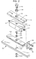
- Fig. 2 is an exploded perspective view showing an essential part of a guide mechanism
- Fig. 3 is a vertical sectional view showing a vertical-type oil damper 170
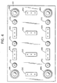
- Fig. 4 is a top plan view showing arrangement of the vibration proofing structure from which a part thereof is omitted for the sake of brevity.
- the vibration proofing structure includes a first or lower base 101 and an elongated rail 103 formed into a T-like shape in section as in the first embodiment and mounted on the lower base 101 by means of a bolt 108.
- the rail 103 is formed at a central portion thereof with an aperture 105, which is formed at a lower portion thereof with a circular depression (not shown). The depression is fitted therein with a bearing 107 and then the bolt 108 is downwardly inserted through the aperture 105.
- the bolt 108 is inserted at a lower portion thereof through a slot-like through-hole 102 of the base 101 and threadedly fitted on a lower end thereof with a double nut 109, resulting in the rail 103 being mounted on the base 101 while keeping a longitudinal axis of the rail 103 perpendicular to longitudinal axis of the through-hole 102.
- the bolt 108 is formed into a diameter smaller than a width of the slot-like through-hole 102 defined in a lateral direction thereof, so that it may be reciprocated in the through-hole 102 along the longitudinal axis of the through-hole 102 in a lateral direction of the base 101, to thereby permit the rail 103 to be reciprocated in the lateral direction of the lower base 101.
- the above-described construction permits the rail 103 to be horizontally rotated about the bearing 107.
- the vibration proofing structure of the second embodiment also includes a guide member 110, which is formed on a lower surface thereof with a recess of a T-like shape in section so as to permit the rail 103 to be snugly fitted in recess, resulting in being mounted on the rail 103 so as to be slidable in a longitudinal direction of the rail 103.
- the guide member 110 is formed with a circular through-hole 146 in a manner to horizontally extend in a longitudinal direction thereof, through which an elongated rod 147 of a circular shape in section is inserted.
- the rod 147 is connected at both ends thereof to both ends of the rail 103 by means of connection plates 148, respectively.
- connection plates 148 respectively.
- connection plates 148 As shown in Figs. 1 and 2
- double nuts 150 and bolts 151 are used for the purpose of the connection as above.
- the guide member 110 is rotatably mounted thereon with a support plate 113, which is formed at a central portion thereof with a stepped through-hole, of which a step 135 is provided thereon with a bearing 145. Then, a bolt 149 is downwardly inserted via the through-hole and threadedly inserted at a lower portion thereof into a threaded hole 142 of the guide member 110, so that the support plate 113 may be mounted on the guide member 110 so as to be rotatable with respect to the guide member 110.
- the support plate 113 is fixedly mounted thereon with a horizontal-type oil damper 120.
- the oil damper 120 may be constructed in substantially the same manner as the oil dampers 20 and 44 incorporated in the first embodiment described above.
- the support plate 113 is formed at portions thereof spaced from each other in a longitudinal direction thereof with bolt holes 114.
- Reference numeral 119 designates a tank for the horizontal-type oil damper 120, which tank is formed into a rectangular cylindrical shape.
- the tank 119 is formed at a bottom thereof with threaded holes 115 in a manner to positionally correspond to or be aligned with the bolt holes 114 of the support plate 113. Then a bolt 116 is threadedly inserted through each of the bolt holes 114 and the threaded hole 115 corresponding thereto, to thereby securely mount the tank 119 on the guide member 110.
- the tank 119 is formed at a central portion of a top thereof with an elongated aperture 123 having a longitudinal axis defined in a longitudinal direction of the tank 119. Also, the tank 119 is formed at portions of the top thereof spaced from each other in a longitudinal direction thereof with small apertures 124, through which oil is fed to spaces defined on both sides of an interior of the tank 119. The small apertures 124 each are closed with a screw after feeding of oil into the tank.
- the tank 119 is provided therein with a pair of pistons 121 in a manner to be arranged in a row in the longitudinal direction thereof. The pistons 121 are connected to each other through a connection bar 126 arranged therebetween.
- connection bar 126 is threadedly mounted on a central portion thereof with a rod 127, which is arranged so as to upwardly extend from the connection bar, resulting in being upwardly projected through the aperture 123 from the tank 119.
- the tank 119 is provided on the top thereof with a holding plate 122, to thereby fully close the small aperture 124.
- the holding plate 122 is formed at a central portion thereof with an aperture 133 of the same configuration as the aperture 123 so as to positionally correspond to the aperture 123.
- a second or upper base 154 is arranged so as to be spaced at a predetermined interval from the holding plate 122.
- the upper base 154 is formed at a portion thereof positionally corresponding to the aperture 123 of the tank 19 and the aperture 133 of the holding plate 122 with an aperture 155.
- the rod 127 upwardly extending from the interior of the tank 119 is upwardly inserted at an upper portion thereof through the apertures 123, 133 and 155 in turn.
- the rod 127 is fitted on a portion thereof position in the aperture 155 of the base 154 with a bearing 156.
- the rod 127 is threadedly securely fitted on a portion thereof positioned above the bearing 156 with a bearing holder 157, to thereby prevent the bearing 156 from being dislocated from the aperture 155.
- the holding plate 122 is threadedly mounted on both sides of an upper surface thereof defined in a longitudinal direction thereof with support rods 125 upwardly extending therefrom.
- the support rods 125 which are arranged so as to be spaced from each other in the longitudinal direction of the holding plate 122 each are upwardly slidably inserted through the upper base 154 and mounted on an upper end thereof with a washer-like spring bearing 136.
- the support rods 125 each are fitted on a portion thereof positioned between each of the spring bearings 136 and the base 154 with a spring 144 of a predetermined spring constant.
- the rod 127 is mounted on an upper end thereof with a washer-like spring bearing 138 and fitted on a portion thereof positioned between the spring bearing 138 and the base 154 with a spring 143 of a predetermined spring constant.
- the spring 143 and 144 may have the same spring constant, which may be set to be about 10 to 25.
- the spring 143 and 144 each may comprise a coiled spring.
- the vertical-type oil damper 170 briefly described above includes a bottom wall 176 and is provided therein with a piston 191, as shown in Fig. 3. Between the piston 191 and the bottom wall 176 is arranged a large spring 192 having a spring constant of about 30 to 80. Thus, the spring constant of the large spring 192 is set to be about three times as large as that of the springs 143 and 144.
- the large spring 192 may comprise a coiled spring. In such arrangement as shown in Fig.
- the springs 143 and 144 and the large spring 192 may be formed into such dimensions as shown in Tables 1 to 4 in correspondence to large load (about 5 tons), intermediate load (about 3 tons) and small load (about 2 tons), respectively, wherein Table 2 shows the dimensions when the large coiled spring 192 comprises a double coil.
- reference numerals 128 and 129 designate nuts for positioning the support rods 125 and rod 127, respectively, and 130 is an oil leakproof lid through which the rod is inserted, of which a mounting manner is detailedly shown in Fig. 5.
- a threaded cylinder 131 of a small length is threadedly fitted in a threaded aperture 132 of the holding plate 122 so as to be concentric with the aperture 133 of the holding plate 122 and then the lid 130 is tightly contacted with the threaded cylinder 131 while being kept threadedly fitted on the rod 127.
- the cylinder 131 is formed into an inner diameter equal to or larger than a maximum diameter of the elongated aperture 133 having a longitudinal axis defined in the longitudinal direction of the tank 119.
- reference numerals 134 and 137 designate double nuts threadedly mounted on the rod 127 and support rods 125, respectively.
- Fig. 3 shows the vertical-type oil damper 170.
- the vertical-type oil damper 170 is fixed on the lower base 101 by means of bolts 188 and double nuts 190 and contacted at an upper portion thereof with a rear surface 153 of the upper base 154 through a hemispherical member 197 mounted on an upper end of a rod 193 through a seat 198.
- reference numerals 179 and 194 each designate a nut for fixing a rod 193 in the piston 191.
- 183 is a through-hole formed via the piston 191 briefly described above for inserting the rod 193 therethrough and 184 is a through-hole formed via a bowl-like cap 181 therethrough.
- the piston 191 is preferably formed on an upper surface thereof with a recess 186 acting as a spring bearing as well as a cap receiver, as shown in Fig. 3. Also the piston 191 is preferably formed on a lower surface thereof with a recess 189 acting as a spring bearing, to thereby facilitate arrangement of the large spring 192 between the piston 191 and the above-described lower wall 176 of the oil damper 170.
- Reference numeral 195 designates an oil leakproof cap for preventing oil from leaking from the oil damper 170.
- the cap 195 is threadedly fitted in the lid 171 of the oil damper 170 and the rod 193 is inserted through a central portion of the cap 195.
- Reference numeral 180 designates through-holes vertically formed via the piston 191 so as to act as an oil passage means.
- Fig. 4 shows an example of arrangement of the vibration proofing structures 100 each including the horizontal-type oil damper 102, the vertical-type oil dampers 170 and struts 185.
- the struts 185 each include a cylinder 174 of a small length having a hemispherical member 172 mounted on an upper end thereof and a cylindrical pedestal 196 for fittedly holding the cylinder 174 therein, as shown in Fig. 13.
- the cylindrical pedestal 196 is provided therein with an elastic cushioning member (not shown), so that the cylinder 174 may be kept elastically upwardly forced to maintain the strut 185 at a predetermined height or to make a height of the strut 185 correspond to an interval between the second or upper base 154 and the first or lower base 101.
- the cylindrical pedestal 196 is fixedly bolted to the lower base 101 which is formed into a rectangular shape.
- the struts 185 are located on the lower rectangular base 101 so as to be in proximity to corners thereof.
- Each one vibration proofing structure 100 including the horizontal-type oil damper is arranged between the struts 185 along each of the short sides of the base 101 in such a manner that a longitudinal axis of the structure 100 lies parallel with a lateral axis of the lower base 101.
- each three vertical-type oil dampers 170 are arranged in a row between the struts 185 along each of long sides of the lower rectangular base 101, wherein two of the three dampers 170 are positioned in proximity to the struts 185, respectively, and the remaining damper 170 is intermediate between the two dampers 170.
- each adjacent two of the vertical-type oil dampers 170 arranged along each of the long sides of the base 101 is arranged the vibration proofing structure 100 including the horizontal-type oil damper in such a manner that the longitudinal axis of the structure 100 lies parallel to a longitudinal axis of the base 100.
- each one vibration proofing structure 100 is arranged between each two vibration proofing structures 100 located on both sides of the base 101 so as to be opposite to each other in such a manner that a longitudinal axis of the one vibration proofing structure is rendered perpendicular to that of the two ones or defined in the lateral direction of the base 101.
- the arrangement shown in Fig. 4 is a mere example, therefore, the number of components arranged may be varied as described depending on a total weight or load of an object such as a construction or the like carried on the upper base 154.
- the total weight is substantially supported by the struts 185.
- the vertical-type oil dampers 170 bear it for a slight period of time.
- adjustment of viscous damping of each of the vertical-type oil dampers 170 by means of the adjustment nut 173 is carried out depending on the total weight and settlement of the arrangement.
- the vibration proofing structure is so constructed that the first or lower base 101 and second or upper base 154 are arranged; the plural rails 103 are mounted at predetermined positions on the lower base 101; the guide members 110 each are fittedly mounted on each of the rails 103 so as to be slidable in the longitudinal direction of the rail 103; each of the plural horizontal-type oil dampers 120 is rotatably mounted on the guide member 110 and includes the tank 119 rotatably mounted on the guide member 110, the pistons 121 arranged in the tank 119, the rod 127 mounted at one end thereof on the pistons so as to render the axis thereof perpendicular to the longitudinal axis of the pistons 121 and outwardly extending at the other end thereof from the tank 119 so as to be slidably inserted through the second or upper base 154; the plural struts 185 each are mounted on the lower base 101 for bearing load downwardly applied through the upper base 154, arranged so as to upwardly extend therefrom and provided
- the lower base 101 is guided by a guide mechanism comprising the rail 103 and guide member 110, to thereby be reciprocated while leaving the oil damper 120, resulting in preventing transmission of vibration to the oil damper 120.
- the base 101 would often fail to smoothly reciprocate due to application, to the oil damper 120, of large load sufficient to cause increased friction to be produced between the guide mechanism and the oil damper 120.
- the oil damper 120 acts as a vibration absorber for absorbing the vibration. More particularly, a phenomenon that the base 101 is to reciprocate while leaving the oil damper 120 and a vibration absorbing action of the oil damper 120 cooperate with each other to effectively absorb vibration.
- Vibration in a direction oblique to the oil damper 120 is often applied to the base 101.
- Application of the oblique vibration causes the lower base 101 to reciprocate by a distance corresponding to a component of the vibration and/or the oil damper 120 to exhibit a vibration absorbing action depending on the component.
- the vibration proofing structure shown in Figs. 1 to 4, as described above, is further constructed that the support rods 125 are mounted on an upper surface of each of the holding plates 122 so as to be spaced from each other in a longitudinal direction of the holding plate 122 and upwardly extend therefrom.
- Each of the support rods 125 is vertically slidably inserted through the second or upper base 154 and provided at an upper end thereof with the washer-like spring bearing 136, and is fitted on the portion thereof defined between the spring bearing 136 and the upper base 154 with the spring 144 of a predetermined spring constant.
- the vibration proofing structure also includes the plural vertical-type oil dampers 170 arranged in proximity to the horizontal-type oil dampers 120.
- the vertical-type oil dampers 170 each include the vertical-type cylinder 187, the piston 191 arranged in the cylinder 187 to define an upper oil chamber 177 and a lower oil chamber 178 therethrough in the cylinder 187 and formed with the oil passage means 180 in a manner to vertically extend therethrough, and the control means for externally controlling the amount of oil transferred through the oil passage means 180 between the upper oil chamber 177 and the lower oil chamber 178.
- the vertical-type oil dampers 170 each are provided therein with the large spring 192 in a manner to be interposed between the piston 191 and the bottom wall 176 of the vertical-type cylinder 187, wherein the large spring 192 has a spring constant about three times as large as the spring constant of each of the springs 143 and 144 described above.
- Such construction effectively prevents vertical vibration such as vibration occurring at a place near a seismic center from being transmitted from the first or lower base 101 to the second or upper base 154.
- the number of springs 143 and 144 arranged is twenty-four (24) which is three times as large as the number (8) of horizontal-type oil dampers 120 and the number of large springs 192 is six (6) which is the same as that of vertical-type oil dampers 170.
- the large spring 192 is arranged between the piston 191 and the bottom 176 of the cylinder 187 while being kept compressed to a predetermined degree, to thereby eliminate an inherent time-lag defect of an oil damper that it exhibits a cushioning action after somewhat delay from application of vibration thereto.
- the vibration proofing structure of the illustrated embodiment exhibits a cushioning action upon application of vertical vibration thereto.
- the struts 185 each are somewhat separated from the upper base 154 immediately after vertical vibration is applied to the lower base 101 and then are returned to the original position in a slight period of time as short as fractions of one second, during which the vertical-type oil dampers 170 each support the upper base 154.
- Application of excessive stress to the horizontal-type oil damper 120 is prevented by compression of the springs 143 and 144.
- vibration which acts to cause each of the struts 185 to push up the upper base 154 is absorbed by the vertical-type oil damper 170.
- the oil damper 170 cooperates with the springs 143 and 144 and large spring 192 to minimise vertical movement of the upper base 154.
- the vertical-type oil burner 170 is provided at the top thereof with the hemispherical member 197 for the purpose of minimising an effect of horizontal vibration of the lower base 101 on the upper base 154.
Landscapes
- Engineering & Computer Science (AREA)
- General Engineering & Computer Science (AREA)
- Mechanical Engineering (AREA)
- Aviation & Aerospace Engineering (AREA)
- Transportation (AREA)
- Physics & Mathematics (AREA)
- Acoustics & Sound (AREA)
- Structural Engineering (AREA)
- Civil Engineering (AREA)
- Life Sciences & Earth Sciences (AREA)
- Geology (AREA)
- Buildings Adapted To Withstand Abnormal External Influences (AREA)
- Vibration Prevention Devices (AREA)
- Seats For Vehicles (AREA)
- Fluid-Damping Devices (AREA)
Claims (4)
- Structure d'amortissement des vibrations pour une charge importante comprenant, une première base (101), une seconde base (154) et une pluralité d'amortisseurs à huile (120), lesdits amortisseurs à huile (120) incluant chacun un réservoir (119), des pistons (121) disposés dans ledit réservoir (119) et une tige (127) ayant une première extrémité et une seconde extrémité, ladite première extrémité étant montée sur lesdits pistons (121) de façon à rendre un axe de ladite tige perpendiculaire à un axe longitudinal desdits pistons (121) et la seconde extrémité de ladite tige s'étendant vers l'extérieur depuis ledit réservoir (119) ; une pluralité de goujons (185) montés chacun sur ladite première base (101) pour supporter la charge appliquée vers le bas à travers ladite seconde base (154) disposés de façon à s'étendre vers le haut à partir de celle-ci et munis sur leur extrémité supérieure d'un élément semi-sphérique (172) ;
caractérisée par :une pluralité de rails (103) montés à des positions prédéterminées sur ladite première base (101) ;des éléments de guidage (110) montés chacun de manière ajustée sur chacun desdits rails (103) de façon à pouvoir coulisser dans une direction longitudinale desdits rails (103) ;lesdits amortisseurs à huile étant des amortisseurs à huile du type horizontal (120), le réservoir (119) de chacun étant monté avec faculté de rotation sur chacun desdits éléments de guidage (110), ladite seconde extrémité de ladite tige (127) s'étendant vers l'extérieur depuis ledit réservoir (119) étant inséré de façon coulissante à travers ladite seconde embase (154) ;des plaques de maintien (122) disposées chacune sur chacun desdits amortisseurs d'huile de type horizontal (120) ;ladite tige (127) étant insérée à travers ladite plaque de maintien (122) de façon à permettre audit amortisseur à huile du type horizontal (120) d'être mis en rotation autour de la tige (127) par rapport à ladite plaque de maintien (122) et étant insérée à travers ladite seconde base (154) tout en étant supportée en rotation au moyen d'un palier (156) de façon à permettre à l'amortisseur à huile du type horizontal (120) d'être mis en rotation par rapport à ladite seconde base(154) ;des tiges de support (125) montées sur une surface supérieure de chacune desdites plaques de maintien (122) de façon à être espacées les unes des autres dans une direction longitudinale de ladite de plaque de maintien (122) et s'étendant vers le haut à partir de celle-ci ;les tiges de support (125) étant chacune insérée de façon coulissable verticalement à travers ladite seconde base (154) et munie au niveau de leur extrémité supérieure d'un palier principal élastique de type rondelle (136) ;lesdites tiges de support (125) étant chacune ajustée sur leur partie définie entre ledit palier principal à ressort (136) et ladite seconde base (154) avec un ressort de tige de support (144) d'une constante de ressort prédéterminée ; etladite tige (127) étant montée sur son extrémité supérieure avec un palier secondaire à ressort du type rondelle (136) et ajusté sur une de ses parties définies entre ledit palier secondaire à ressort (136) et la seconde base (154) avec un ressort de tige (143) d'un constante de ressort prédéterminée ; etune pluralité d'amortisseurs à huile du type vertical (170) disposée à proximité desdits amortisseurs à huile du type horizontal (120) ;lesdits amortisseurs à huile du type vertical (170) incluant chacun un cylindre du type vertical (187), un piston (191) disposé dans ledit cylindre (187) pour définir une chambre à huile supérieure (177) et une chambre à huile inférieure (178) à travers tout ledit cylindre et formé avec un moyen de passage d'huile (180) de manière à s'étendre verticalement à travers celui-ci, et un moyen de commande pour commander de manière externe la quantité d'huile transférée à travers ledit moyen de passage d'huile entre ladite chambre d'huile supérieure (177) et ladite chambre d'huile inférieure (178) ;lesdits amortisseurs à huile du type vertical (170) étant chacun pourvu dans celui-ci d'un ressort de grande dimension (192) de manière à être interposé entre ledit piston (191) et une partie inférieure (176) dudit cylindre du type vertical (170), ledit ressort de grande dimension (192) ayant une constante de ressort environ trois fois plus grande que ladite constante de ressort dudit ressort à tige (143) et de chacun desdits ressorts à tige de support (144). - Structure d'amortissement des vibrations selon la revendication 1, dans laquelle ladite constante de ressort dudit ressort de tige (143) et de chacun desdits ressorts de tige de support (144) est fixée pour être environ de 10 à 25.
- Structure d'amortissement des vibrations selon la revendication 1, dans laquelle ladite constante de ressort dudit ressort de grande dimension (192) est fixée pour être d'environ 30 à 80.
- Structure d'amortissement des vibrations selon la revendication 1, dans laquelle ledit moyen de commande pour commander de manière externe la quantité d'huile transférée entre ladite chambre d'huile supérieure et ladite chambre d'huile inférieure à travers ledit moyen de passage d'huile (180) comprend :ledit ressort de grande dimension (192) étant disposé entre ledit piston (191) et ladite partie inférieure (176) dudit cylindre (187) tout en étant maintenu comprimé à un degré prédéterminé.un chapeau du type bol (181) posé sur ledit piston (191) pour commander la quantité d'huile transférée entre ladite chambre d'huile supérieure (177) et ladite chambre d'huile inférieure (178) à travers ledit moyen de passage d'huile (180) ;un moyen de ressort (182) disposé entre ledit chapeau (181) et une surface supérieure (175) dudit piston (191) pour forcer vers le haut ledit chapeau (182) ;un élément de tige (193) qui est disposé verticalement dans ledit cylindre du type vertical (187) de façon à dépasser vers le haut au niveau de son extrémité supérieure depuis ledit cylindre du type vertical (170) et sur lequel ledit piston (191) est ajusté ;un tuyau raccordé sur ledit élément de tige (193) dans ledit cylindre du type vertical (187) pour ajuster un espace entre ledit chapeau ( 181) et ladite surface supérieure dudit piston (191) ; etun écrou d'ajustement ajusté par filetage sur ledit élément de tige (193) de façon à être positionné au niveau d'une extrémité supérieure dudit tuyau, de sorte qu'un léger déplacement vertical dudit écrou d'ajustement permet que l'espace entre ledit chapeau (181) et ladite surface supérieure dudit piston (191) soit ajusté pour commander la quantité d'huile transférée entre ladite chambre d'huile supérieure (177) et ladite chambre d'huile inférieure (178) ;
Applications Claiming Priority (7)
| Application Number | Priority Date | Filing Date | Title |
|---|---|---|---|
| JP14712293 | 1993-05-14 | ||
| JP14712293 | 1993-05-14 | ||
| JP147122/93 | 1993-05-14 | ||
| JP12795794 | 1994-05-06 | ||
| JP12795794A JP3666028B2 (ja) | 1993-05-14 | 1994-05-06 | 防振機構 |
| JP127957/94 | 1994-05-06 | ||
| EP19940303346 EP0625649B1 (fr) | 1993-05-14 | 1994-05-10 | Structure amortissant les vibrations |
Related Parent Applications (1)
| Application Number | Title | Priority Date | Filing Date |
|---|---|---|---|
| EP19940303346 Division EP0625649B1 (fr) | 1993-05-14 | 1994-05-10 | Structure amortissant les vibrations |
Publications (3)
| Publication Number | Publication Date |
|---|---|
| EP0849496A2 EP0849496A2 (fr) | 1998-06-24 |
| EP0849496A3 EP0849496A3 (fr) | 1999-02-10 |
| EP0849496B1 true EP0849496B1 (fr) | 2002-04-10 |
Family
ID=26463770
Family Applications (2)
| Application Number | Title | Priority Date | Filing Date |
|---|---|---|---|
| EP19940303346 Expired - Lifetime EP0625649B1 (fr) | 1993-05-14 | 1994-05-10 | Structure amortissant les vibrations |
| EP97202788A Expired - Lifetime EP0849496B1 (fr) | 1993-05-14 | 1994-05-10 | Structure amortissant les vibrations |
Family Applications Before (1)
| Application Number | Title | Priority Date | Filing Date |
|---|---|---|---|
| EP19940303346 Expired - Lifetime EP0625649B1 (fr) | 1993-05-14 | 1994-05-10 | Structure amortissant les vibrations |
Country Status (3)
| Country | Link |
|---|---|
| EP (2) | EP0625649B1 (fr) |
| JP (1) | JP3666028B2 (fr) |
| DE (2) | DE69409573T2 (fr) |
Cited By (1)
| Publication number | Priority date | Publication date | Assignee | Title |
|---|---|---|---|---|
| CN108773302A (zh) * | 2018-07-11 | 2018-11-09 | 深圳达芬奇创新科技有限公司 | 一种汽车座椅的缓冲装置 |
Families Citing this family (18)
| Publication number | Priority date | Publication date | Assignee | Title |
|---|---|---|---|---|
| JP3803369B2 (ja) * | 1994-01-25 | 2006-08-02 | マイナス ケー テクノロジー,インコーポレイテッド | 振動遮断装置 |
| DE4411470B4 (de) * | 1994-04-01 | 2004-09-02 | Linde Ag | Flurförderzeug mit einer Plattform |
| JP4946359B2 (ja) * | 2006-11-01 | 2012-06-06 | 美和ロック株式会社 | スプリングダンパー |
| KR101231653B1 (ko) * | 2011-05-30 | 2013-02-14 | 김해남 | 내진장치 |
| GB2494884B (en) * | 2011-09-21 | 2016-01-20 | Palletforce Plc | Apparatus and method for the identification and weighing of cargo |
| KR101227947B1 (ko) * | 2012-10-09 | 2013-01-30 | (주)테크윈시스템 | 내진 수배전 장치 |
| JP6122881B2 (ja) * | 2015-01-14 | 2017-04-26 | 株式会社畑鉄工所 | 回転式粉末圧縮成型装置用圧力緩衝装置及びこれを備える回転式粉末圧縮成型装置 |
| CN107091296A (zh) * | 2017-06-05 | 2017-08-25 | 长江师范学院 | 机械设备夹持转换式减振方法 |
| CN107218222A (zh) * | 2017-06-07 | 2017-09-29 | 河南多普电子科技有限公司 | 一种智能自动控制螺杆制冷压缩机 |
| CN107697854B (zh) * | 2017-11-03 | 2024-07-12 | 安徽合力股份有限公司 | 一种用于站驾式叉车的减振可调悬浮式站板 |
| JP6469291B1 (ja) * | 2018-07-17 | 2019-02-13 | Kyb株式会社 | 転倒防止装置 |
| CN109114158B (zh) * | 2018-08-20 | 2020-11-24 | 常熟理工学院 | 一种轿车用组合减振装置 |
| CN110056595B (zh) * | 2019-05-11 | 2021-12-31 | 泉州市博汉机械股份有限公司 | 一种限位减震器结构 |
| CN112456048A (zh) * | 2020-11-26 | 2021-03-09 | 浙江东腾智能装备有限公司 | 一种可自动升降旋转平台地轨道平车 |
| JP7479304B2 (ja) * | 2021-01-07 | 2024-05-08 | 日立Geニュークリア・エナジー株式会社 | 粘弾性ダンパで配管を支持する支持構造 |
| CN114918979B (zh) * | 2022-06-30 | 2024-04-26 | 上海擎朗智能科技有限公司 | 一种浮动托盘及机器人 |
| CN115492894B (zh) * | 2022-08-04 | 2023-05-23 | 哈尔滨工程大学 | 链式面板液囊支撑的高效减振基座 |
| KR200499043Y1 (ko) * | 2022-11-16 | 2025-04-11 | 주식회사 보고코퍼레이션 | 물탱크 지지장치 및 그 설치 방법 |
Family Cites Families (6)
| Publication number | Priority date | Publication date | Assignee | Title |
|---|---|---|---|---|
| US2312718A (en) * | 1941-04-23 | 1943-03-02 | Haroutium K Kouyoumjian | Shock absorber |
| US2760552A (en) * | 1952-11-13 | 1956-08-28 | Frederick J Decker | Pneumatic seat |
| FR1362687A (fr) * | 1963-04-26 | 1964-06-05 | Vibrachoc Sa | Organe de liaison variable, dispositif d'asservissement et dispositif d'amortissement d'appareils tels que les gyro-compas en comportant application |
| US3625466A (en) * | 1970-08-20 | 1971-12-07 | Marshall Research & Dev Corp | Vibration isolator |
| JPS60184736A (ja) * | 1984-02-29 | 1985-09-20 | Sanwa Tekki Corp | 定置型油圧防振器 |
| JP2676559B2 (ja) * | 1989-10-23 | 1997-11-17 | 正彦 池田 | 防振機構 |
-
1994
- 1994-05-06 JP JP12795794A patent/JP3666028B2/ja not_active Expired - Lifetime
- 1994-05-10 DE DE1994609573 patent/DE69409573T2/de not_active Expired - Fee Related
- 1994-05-10 DE DE1994630394 patent/DE69430394T2/de not_active Expired - Fee Related
- 1994-05-10 EP EP19940303346 patent/EP0625649B1/fr not_active Expired - Lifetime
- 1994-05-10 EP EP97202788A patent/EP0849496B1/fr not_active Expired - Lifetime
Cited By (1)
| Publication number | Priority date | Publication date | Assignee | Title |
|---|---|---|---|---|
| CN108773302A (zh) * | 2018-07-11 | 2018-11-09 | 深圳达芬奇创新科技有限公司 | 一种汽车座椅的缓冲装置 |
Also Published As
| Publication number | Publication date |
|---|---|
| DE69430394T2 (de) | 2003-10-23 |
| JPH0727171A (ja) | 1995-01-27 |
| DE69430394D1 (de) | 2002-05-16 |
| EP0625649B1 (fr) | 1998-04-15 |
| EP0625649A1 (fr) | 1994-11-23 |
| JP3666028B2 (ja) | 2005-06-29 |
| EP0849496A3 (fr) | 1999-02-10 |
| EP0849496A2 (fr) | 1998-06-24 |
| DE69409573T2 (de) | 1998-12-24 |
| DE69409573D1 (de) | 1998-05-20 |
Similar Documents
| Publication | Publication Date | Title |
|---|---|---|
| EP0849496A2 (fr) | Structure amortissant les vibrations | |
| DE102010008466B4 (de) | Einfederungsanschlag-Baugruppe für ein Fahrzeug | |
| FI71902B (fi) | Vibrationsdaempande sitsstoed | |
| US5794912A (en) | Constant horizontal natural frequency vibration isolation mount pad insert | |
| DE69008264T2 (de) | Verbesserungen an hydraulischen Schwingungsdämpfern. | |
| DE3347273A1 (de) | Elastisches lager mit einem hydraulischen daempfer | |
| US4509781A (en) | Isolated bumper for damping vibrations in vehicles | |
| KR101227619B1 (ko) | 차량용 서스펜션 및 이를 구비한 차량 | |
| WO2019007627A1 (fr) | Jambe de ressort pneumatique comprenant un couvercle de fermeture étanchéifié | |
| CA1068207A (fr) | Siege qui amortit les vibrations | |
| US5549282A (en) | Vibration proofing structure | |
| EP0344415B1 (fr) | Dispositif de support pour le moteur d'un véhicule automobile | |
| US4228984A (en) | Vibration attenuator seat | |
| DE3921612A1 (de) | Fluidgefuelltes elastisches aufhaengungselement | |
| EP1080970A1 (fr) | Structure support anti-vibrations pour moteur | |
| DE4325172C1 (de) | Luftfeder mit einem elastomeren Luftfederbalg und einer integrierten Dämpfungseinrichtung | |
| JP2676559B2 (ja) | 防振機構 | |
| EP0462510B1 (fr) | Unité d'amortissement, pour systèmes de suspension dans voitures automobiles | |
| CN219911626U (zh) | 一种激光雷达的减震装置、激光雷达系统和无人搬运车 | |
| WO2017001228A1 (fr) | Ensemble pour toit de véhicule et système pour véhicule à moteur | |
| KR200160615Y1 (ko) | 쇽업소버의 댐퍼스프링구조 | |
| KR100199744B1 (ko) | 자동차용 쇽업소버의 감쇠력을 측정하기 위한 지그 | |
| DE4344437C1 (de) | Elastisches Lager | |
| DE4213043C2 (de) | Hydropneumatisches Dämpfer-Federelement | |
| DE19959842A1 (de) | Luftfeder mit einem Schwingungsdämpfer |
Legal Events
| Date | Code | Title | Description |
|---|---|---|---|
| PUAI | Public reference made under article 153(3) epc to a published international application that has entered the european phase |
Free format text: ORIGINAL CODE: 0009012 |
|
| AC | Divisional application: reference to earlier application |
Ref document number: 625649 Country of ref document: EP |
|
| AK | Designated contracting states |
Kind code of ref document: A2 Designated state(s): DE FR GB IT SE |
|
| PUAL | Search report despatched |
Free format text: ORIGINAL CODE: 0009013 |
|
| AK | Designated contracting states |
Kind code of ref document: A3 Designated state(s): DE FR GB IT SE |
|
| 17P | Request for examination filed |
Effective date: 19990805 |
|
| 17Q | First examination report despatched |
Effective date: 19991012 |
|
| GRAG | Despatch of communication of intention to grant |
Free format text: ORIGINAL CODE: EPIDOS AGRA |
|
| GRAG | Despatch of communication of intention to grant |
Free format text: ORIGINAL CODE: EPIDOS AGRA |
|
| GRAH | Despatch of communication of intention to grant a patent |
Free format text: ORIGINAL CODE: EPIDOS IGRA |
|
| RAP1 | Party data changed (applicant data changed or rights of an application transferred) |
Owner name: KIYOKO, IKEDA |
|
| GRAH | Despatch of communication of intention to grant a patent |
Free format text: ORIGINAL CODE: EPIDOS IGRA |
|
| REG | Reference to a national code |
Ref country code: GB Ref legal event code: IF02 |
|
| GRAA | (expected) grant |
Free format text: ORIGINAL CODE: 0009210 |
|
| AC | Divisional application: reference to earlier application |
Ref document number: 625649 Country of ref document: EP |
|
| AK | Designated contracting states |
Kind code of ref document: B1 Designated state(s): DE FR GB IT SE |
|
| REF | Corresponds to: |
Ref document number: 69430394 Country of ref document: DE Date of ref document: 20020516 |
|
| ET | Fr: translation filed | ||
| PLBE | No opposition filed within time limit |
Free format text: ORIGINAL CODE: 0009261 |
|
| STAA | Information on the status of an ep patent application or granted ep patent |
Free format text: STATUS: NO OPPOSITION FILED WITHIN TIME LIMIT |
|
| 26N | No opposition filed |
Effective date: 20030113 |
|
| PGFP | Annual fee paid to national office [announced via postgrant information from national office to epo] |
Ref country code: GB Payment date: 20030422 Year of fee payment: 10 |
|
| PG25 | Lapsed in a contracting state [announced via postgrant information from national office to epo] |
Ref country code: GB Free format text: LAPSE BECAUSE OF NON-PAYMENT OF DUE FEES Effective date: 20040510 |
|
| GBPC | Gb: european patent ceased through non-payment of renewal fee |
Effective date: 20040510 |
|
| PGFP | Annual fee paid to national office [announced via postgrant information from national office to epo] |
Ref country code: DE Payment date: 20051128 Year of fee payment: 12 |
|
| PGFP | Annual fee paid to national office [announced via postgrant information from national office to epo] |
Ref country code: FR Payment date: 20051129 Year of fee payment: 12 |
|
| PGFP | Annual fee paid to national office [announced via postgrant information from national office to epo] |
Ref country code: SE Payment date: 20051130 Year of fee payment: 12 |
|
| PG25 | Lapsed in a contracting state [announced via postgrant information from national office to epo] |
Ref country code: SE Free format text: LAPSE BECAUSE OF NON-PAYMENT OF DUE FEES Effective date: 20060511 |
|
| PGFP | Annual fee paid to national office [announced via postgrant information from national office to epo] |
Ref country code: IT Payment date: 20060531 Year of fee payment: 13 |
|
| PG25 | Lapsed in a contracting state [announced via postgrant information from national office to epo] |
Ref country code: DE Free format text: LAPSE BECAUSE OF NON-PAYMENT OF DUE FEES Effective date: 20061201 |
|
| EUG | Se: european patent has lapsed | ||
| REG | Reference to a national code |
Ref country code: FR Ref legal event code: ST Effective date: 20070131 |
|
| PG25 | Lapsed in a contracting state [announced via postgrant information from national office to epo] |
Ref country code: FR Free format text: LAPSE BECAUSE OF NON-PAYMENT OF DUE FEES Effective date: 20060531 |
|
| PG25 | Lapsed in a contracting state [announced via postgrant information from national office to epo] |
Ref country code: IT Free format text: LAPSE BECAUSE OF NON-PAYMENT OF DUE FEES Effective date: 20070510 |