EP0849601A2 - Vorrichtung und Verfahren zur Bestimmung des Vorzeichens einer Phasenverschiebung zweier elektrischer Signale - Google Patents
Vorrichtung und Verfahren zur Bestimmung des Vorzeichens einer Phasenverschiebung zweier elektrischer Signale Download PDFInfo
- Publication number
- EP0849601A2 EP0849601A2 EP97120612A EP97120612A EP0849601A2 EP 0849601 A2 EP0849601 A2 EP 0849601A2 EP 97120612 A EP97120612 A EP 97120612A EP 97120612 A EP97120612 A EP 97120612A EP 0849601 A2 EP0849601 A2 EP 0849601A2
- Authority
- EP
- European Patent Office
- Prior art keywords
- signal
- sign
- comparator
- receiving
- predetermined
- Prior art date
- Legal status (The legal status is an assumption and is not a legal conclusion. Google has not performed a legal analysis and makes no representation as to the accuracy of the status listed.)
- Granted
Links
Images


Classifications
-
- G—PHYSICS
- G01—MEASURING; TESTING
- G01R—MEASURING ELECTRIC VARIABLES; MEASURING MAGNETIC VARIABLES
- G01R29/00—Arrangements for measuring or indicating electric quantities not covered by groups G01R19/00 - G01R27/00
- G01R29/18—Indicating phase sequence; Indicating synchronism
Definitions
- the present invention relates to a device and a Method for determining the sign of a phase shift a substantially identical first and second periodic electrical signal on a corresponding first and second electrical conductors, in particular for Determination of the rotating field direction in a three-phase network.
- Rotary field direction determination devices are always then used when the three sinusoidal shifts, each shifted by 120 ° Signals of a three-phase network or three-phase network not clearly assigned to the existing ladders can.
- the phase sequence must be on all connections agree so that the unit works properly.
- DE 40 02 603 A1 also discloses a measuring device without ground contact known which one arranged in a handle Indicator flag that can be connected to a reference potential is.
- the discharge tab runs parallel to the handle one of two test probes and is active during measuring operation together with a user's hand gripping the handle as a capacitor against earth.
- Earthing contacts and leakage tabs are problematic as they require a firm touch by the user. Farther can the length or the spatial arrangement of a connecting line Difficulty from grounding contacts or leakage tabs make, because it determines the direction of rotation used capacitive currents are influenced in this way can that they are not sized to perform the measurement not enough anymore.
- DE 31 17 284 A1 describes a circuit arrangement for Monitoring of a symmetrical three-phase current is known. This has one for each conductor of the three-phase system Zero crossing detector, which at a respective Zero crossing generates a corresponding pulse. These impulses are fed to a rotating field monitoring circuit, which determines whether between two zero crossing pulses the assigned to two successively connected phases a zero crossing pulse of the third phase occurs. Is if this is the case, then there is an incorrect assignment. A Determination of the rotating field direction is known with this Circuit arrangement not possible, since it is only by means of a logic device determines whether a zero crossing at all the third phase.
- this object is achieved by the in claim 1 specified device solved, so by a device for Determination of the sign of a phase shift first and second substantially identical periodic electrical signal on a corresponding first and second electrical conductor, in particular for determining the Rotation field direction in a three-phase network, with a tap to attack the first signal from the first Conductor and the second signal from the second conductor; one Trigger device for receiving the tapped first signal and establishing a time reference point and / or a time reference window within the signal period the first signal and outputting a corresponding trigger signal; and a determination device for receiving the Trigger signal and the tapped second signal and determining taking the sign of the phase shift into account of at least the value of the second signal on temporal reference point and / or the course of the second signal within the time reference window.
- the measurement result can be specified simply and clearly.
- the structure is simple and clear to implement and can essentially on two test probes, microelectronics, e.g. a microprocessor, and two lights, e.g. LEDs, limit.
- the rotating field direction in a three-phase network by measurement determine on any two of the three existing outer conductors, because the phase position of the third outer conductor results out of it automatically.
- the trigger device designed to have a predetermined, e.g. one increasing, zero crossing of the first signal as temporal Specifies the reference point.
- the determination device is is designed so that it is the sign the phase shift from the sign of the second Signal determined at the time reference point.
- the Trigger device a first comparator device for receiving the first signal and comparing it with one predetermined reference potential and a differentiator to differentiate the output signal of the first Comparator device on. Furthermore, the determination device points a second comparator device for receiving the second signal and comparing it with the predetermined one Reference potential and a storage device for Receiving the output signal of the second comparator device and the output signal of the differentiator device on.
- the storage device is designed such that with each output signal of the differentiator device a predetermined sign the sign of the output signal the second comparator device stores.
- the Storage device on a flip-flop device.
- the trigger device designed such that it corresponds to a predetermined, e.g. an increasing, zero crossing of the first Signal following half signal period of the first signal as defines a time reference window.
- the determination device is designed in such a way that the sign the phase shift by determining whether the second signal within the time reference window a predetermined, e.g. has a sloping, zero crossing.
- the Trigger device a first comparator device for receiving the first signal and comparing it with one predetermined reference potential and a differentiator to differentiate the output signal of the first Comparator device and a time window generating device for receiving the output signal of the differentiating device and generating a time window signal at each Output pulse of the differentiator device with a predetermined sign.
- the determination device points a second comparator device for receiving the second Signals and comparing it with the predetermined Reference potential and a storage device for receiving of the time window signal of the time window generating device and the output signal of the second comparator device.
- the storage device is designed such that it the occurrence of the predetermined zero crossing of the second Stores signals within the time reference window.
- the Storage device on a Schmitt trigger device is a Schmitt trigger device.
- the trigger device designed to have a predetermined, e.g. positive, half wave of the first signal as temporal Set reference window.
- the determination device is designed so that at least that second signal digitizes and stores and the sign the phase shift by determining whether the digitized second signal within the time reference window predetermined, e.g. has a falling edge.
- the Trigger device a first comparator device for receiving the first signal and comparing it with one predetermined reference potential.
- the destination facility has a second comparator device for receiving the second signal and comparing it with the predetermined one Reference potential and a logic processing device for receiving the output signal of the first comparator device and the second comparator device.
- the logic processing device is designed in such a way that that they determine the sign of the phase shift by whether the second signal has a predetermined edge if the output signal of the first comparator device assumes a predetermined state.
- a display device is connected to the determining device to indicate the specific sign of the phase shift intended.
- the display device a lamp, e.g. an LED.
- the tap device is designed in such a way that only resistive Components for tapping the first and second signals are provided. Reactive resistances can therefore have no influence exercise on the measurement.
- the first and second electrical conductors with a common circuit point, which is at a certain potential.
- the coupling of the common Switching point to the reference potential to almost any Sort of.
- the common Switching point during the determination of the sign the phase shift can be connected to the earth potential.
- a galvanic connection device is provided for connection the common node with the ground potential.
- connection the common node with the ground potential a capacitive one that runs over the human body Connection device provided.
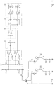
- Fig. 1 shows a schematic overview of three preferred Embodiments of the device according to the present invention.
- reference numerals L1 and L2 denote a first and second electrical conductor, which a first and second in essentially identical sinusoidal electrical signal lead, the two signals a certain phase shift to each other.
- This phase shift lies in the range between -180 ° and + 180 ° (- ⁇ and + ⁇ ).
- the device according to the invention serves to determine which Sign showing the phase shift, i.e. which of the both signals run ahead or run after the other.
- the two electrical conductors have internal or external inserted resistors 20a, 20b, 20c and 20d and are on a common circuit point K connected to each other, which is at a predetermined potential and over a another such resistor 21 with a connection point V is connected.
- connection point V a connection of the common node K with the earth potential PEN three different types of connecting device 11, 12 and 13 are done.
- Reference numeral 11 denotes a connection device for Connection of the common node K to the earth potential PEN via a galvanic connection line.
- Reference numeral 12 denotes a connection device for Connection of the common node K to the earth potential PEN via a resistive, via a touch electrode and connecting line extending through the human body 100.
- R and 101 denote a respective resistance and 102 a capacity.
- Reference numeral 13 denotes a connection device for Connection of the common node K to the earth potential PEN about a capacitive, about the human body 100 connecting cables.
- C and 102 denote a respective capacitance and 101 a resistor.
- Reference numeral 25 denotes a trigger device for receiving the tapped first signal of the first conductor L1.
- the trigger device establishes a time reference point and / or a time reference window within the signal period of the first signal and gives a corresponding one Trigger signal off.
- the trigger device generates 25 to an arbitrarily definable, but constant phase position the first signal, e.g. certain zero crossing or maximum or minimum or certain slope, a momentum.
- This point in time pulse is sent to a determination device 31 passed the polarity of the second signal at the time of the momentum pulse and from this the sign the phase shift is determined, i.e. a point in time analysis carries out.
- the trigger device generates 25 to an arbitrarily definable, but constant phase position the first signal, e.g. certain zero crossing or maximum or minimum or certain slope, a time window pulse for the duration of half a signal period of the first signal.
- This time window pulse is sent to a determination device 32 passed, which detects whether the second signal during the Duration of the time window pulse a predetermined zero crossing and from it the sign of the phase shift determined, i.e. performs a time window analysis.
- the trigger device generates 25 also a time window pulse for the duration of one half signal period of the first signal, this with a certain sign of the first signal coincides.
- This time window pulse is sent to a determination device 33 passed, which also digitizes the second signal Form is supplied.
- This determination device 33 detects whether the second signal during the time window pulse has a predetermined edge, and determines from that Sign of the phase shift, therefore performs a logic analysis by.
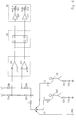
- Fig. 2 shows a schematic representation of the first preferred Embodiment of the device according to the present Invention.
- the trigger device has in the first embodiment a first comparator 301 for receiving the first signal and comparing it with a predetermined reference potential, expediently earth potential, and a differentiator 41 for differentiating the output signal of the first Comparator 301 on.
- the determination device points in the first embodiment a second comparator 311 for receiving the second Signals and comparing it with the predetermined reference potential and a storage device 42 for receiving the output signal of the differentiator 41 at an input E1 and the output signal of the second comparator 311 on one Input E2 on.
- the storage device 42 is designed such that it each output pulse of differentiator 41 with a positive Sign the sign of the output signal of the second Comparator 311 stores.
- the output pulses could also of the differentiator 41 with a negative sign be used for this purpose.
- the storage device 42 has a flip-flop device.
- the memory device 42 has two outputs A1 and A2, associated with the display 50.
- the first exit A1 activates a "right" display 501, 502 to display one Right shift of the second signal compared to the first Signal, i.e. a negative sign of the phase shift.
- the second output A2 activates a "left" display 511, 512 to indicate a left shift of the second signal compared to the first signal, i.e. a positive sign the phase shift.
- the display 50 consists of one Driver 501, 511 and a lamp 502 controlled thereby, 512.
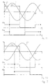
- FIG. 3 shows diagrams of the phase-shifted signals of the two electrical conductor L1, L2 to explain the first Embodiment according to FIG. 2.
- absc issa Time and the respective signal amplitude is plotted on the ordinate.
- Fig. 3.1 shows the case where the first signal is on the first Conductor L1 the second signal on the second conductor L2 runs ahead.
- the differentiator 41 gives each time with an increasing zero crossing of the first signal a positive impulse, because that always changes Signal of the comparator 301 with a rising edge.
- Fig. 3.2 shows the case in which the second signal on the second conductor L2 the first signal on the first conductor L1 runs ahead.
- Fig. 4 shows a schematic representation of the second preferred Embodiment of the device according to the present Invention.
- the trigger device has in the second embodiment also a first comparator 301 for receiving the first Signals and comparing it with a predetermined Reference potential, expediently earth potential, and one Differentiator 41 for differentiating the output signal of the first comparator.
- a time window generating device 44 expediently a monoflop, for receiving of the output signal of the differentiator 41 and generating one Time window signal with each output pulse of the differentiator 41 with a positive sign.
- a time window generating device 44 expediently a monoflop, for receiving of the output signal of the differentiator 41 and generating one Time window signal with each output pulse of the differentiator 41 with a positive sign.
- it can Time window also in response to an output pulse from the Differentiator 41 generated with a negative sign will.
- the determination device points in the second embodiment also a second comparator 311 for receiving the second signal and comparing it with the predetermined one Reference potential and a storage device 46 for Receiving the output signal of the time window generating device 44 at a first input E1 and the output signal of the second comparator at a second input E2.
- the storage device 46 is designed such that it Occurrence of a falling zero crossing of the second signal stores within the time reference window.
- the storage device 46 expediently comprises one Schmitt trigger device. Of course she could too Save the occurrence of an increasing zero crossing.
- FIG. 5 shows diagrams of the phase-shifted signals of the two electrical conductor L1, L2 to explain the second Embodiment according to FIG. 4.
- absc issa Time and the respective signal amplitude is plotted on the ordinate.
- Fig. 5.1 shows the case in which the first signal on the first Conductor L1 the second signal on the second conductor L2 runs ahead.
- the differentiator 41 gives each time with an increasing zero crossing of the first signal a positive impulse, because that always changes Signal of the comparator 301 with a rising edge.
- the time window generator 44 respondingly generated as in Fig. 5.1 by itself the highlighted points are followed by a dashed time window half a signal period T / 2 of the first signal, the time window generator 44 generates a time window signal with the length T / 2 and puts this at the entrance E1 of the storage device 46.
- Fig. 5.2 shows the case in which the second signal on the second conductor L2 the first signal on the first conductor L1 runs ahead.
- Fig. 6 shows a schematic representation of the third preferred Embodiment of the device according to the present Invention.
- the trigger device has in the third embodiment also a first comparator 301 for receiving the first Signals and comparing it with a predetermined Reference potential, expediently earth potential.
- the determination device points in the third embodiment a second comparator 311 for receiving the second Signals and comparing it with the predetermined reference potential and a logic processing device 48 for Receiving the output signal of the first comparator 301 on a first input E1 and the second comparator 311 a second input E2.
- the logic processing device 48 is designed such that the sign of the phase shift by determining whether the second signal has a falling edge if that Output signal of the first comparator 301 an H state occupies, determines.
- the presence can also a rising edge, and it can too the L state of the output signal of the first comparator 301 can be used as a trigger signal.
- Fig. 7 shows diagrams of the phase-shifted signals of the two electrical conductor L1, L2 to explain the second Embodiment according to Fig. 6.
- absc issa Time and the respective signal amplitude is plotted on the ordinate.
- Fig. 7.1 shows the case in which the first signal on the first Conductor L1 the second signal on the second conductor L2 runs ahead.
- X1 denotes the digitized form of the first Signal of the first conductor L1 corresponding to the output signal of the first comparators 301 and X2 the digitized form of the second signal of the second conductor L2 corresponding to the output signal of the second comparator 311.
- Fig. 7.1 by highlighted points in the signal curve of the digitized indicated first and second signals X1, X2, the second digitized signal X2 during the high state of the first digitized signal X1 due to the positive sign the phase shift always has a falling edge. This is detected by the logic processing device 48, saved and brought to display 50 via output A2 in which consequently the left lamp 512 lights up.
- Fig. 7.2 shows the case in which the second signal on the second conductor L2 the first signal on the first conductor L1 runs ahead.
- first to third embodiments are discussed individually they can of course be combined as desired. Also multiple successive events, i.e. Measurements linked in successive signal periods, e.g. be averaged. This is particularly noisy in the case of a lot of noise Significant signals.
Landscapes
- Physics & Mathematics (AREA)
- General Physics & Mathematics (AREA)
- Measuring Phase Differences (AREA)
- Control Of Eletrric Generators (AREA)
Abstract
Description
- Fig. 1
- eine schematische Übersicht über drei bevorzugte Ausführungsformen der Vorrichtung gemäß der vorliegenden Erfindung;
- Fig. 2
- eine schematische Darstellung der ersten bevorzugten Ausführungsform der Vorrichtung gemäß der vorliegenden Erfindung;
- Fig. 3
- Diagramme der phasenverschobenen Signale zweier elektrischer Leiter zur Erläuterung der ersten Ausführungsform gemäß Fig. 2, nämlich Fig. 3.1 den Fall, bei dem das Signal auf dem ersten Leiter demjenigen auf dem zweiten Leiter vorausläuft, und Fig. 3.2 den Fall, bei dem das Signal auf dem zweiten Leiter demjenigen auf dem ersten Leiter vorausläuft;
- Fig. 4
- eine schematische Darstellung der zweiten bevorzugten Ausführungsform der Vorrichtung gemäß der vorliegenden Erfindung;
- Fig. 5
- Diagramme der phasenverschobenen Signale zweier elektrischer Leiter zur Erläuterung der zweiten Ausführungsform gemäß Fig. 4, nämlich Fig. 5.1 den Fall, bei dem das Signal auf dem ersten Leiter demjenigen auf dem zweiten Leiter vorausläuft, und Fig. 5.2 den Fall, bei dem das Signal auf dem zweiten Leiter demjenigen auf dem ersten Leiter vorausläuft;
- Fig. 6
- eine schematische Darstellung der dritten bevorzugten Ausführungsform der Vorrichtung gemäß der vorliegenden Erfindung; und
- Fig. 7
- Diagramme der phasenverschobenen Signale zweier elektrischer Leiter zur Erläuterung der zweiten Ausführungsform gemäß Fig. 6, nämlich Fig. 7.1 den Fall, bei dem das Signal auf dem ersten Leiter demjenigen auf dem zweiten Leiter vorausläuft, und Fig. 7.2 den Fall, bei dem das Signal auf dem zweiten Leiter demjenigen auf dem ersten Leiter vorausläuft.
Claims (20)
- Vorrichtung zur Bestimmung des Vorzeichens einer Phasenverschiebung eines ersten und zweiten im wesentlichen identischen periodischen elektrischen Signals auf einem entsprechenden ersten und zweiten elektrischen Leiter, insbesondere zur Bestimmung der Drehfeldrichtung in einem Dreiphasennetz, mit:einer Abgriffseinrichtung zum Abgreifen des ersten Signals vom ersten Leiter und des zweiten Signals vom zweiten Leiter;einer Triggereinrichtung zum Empfangen des abgegriffenen ersten Signals und Festlegen eines zeitlichen Bezugspunkts und/oder eines zeitlichen Bezugsfensters innerhalb der Signalperiode des ersten Signals und Ausgeben eines entsprechenden Triggersignals; undeiner Bestimmungseinrichtung zum Empfangen des Triggersignals und des abgegriffenen zweiten Signals und Bestimmen des Vorzeichens der Phasenverschiebung unter Berücksichtigung von zumindest dem Wert des zweiten Signals am zeitlichen Bezugspunkt und/oder dem Verlauf des zweiten Signals innerhalb des zeitlichen Bezugsfensters.
- Vorrichtung nach Anspruch 1, dadurch gekennzeichnet, daß die Triggereinrichtung derart gestaltet ist, daß sie einen vorbestimmten Nulldurchgang des ersten Signals als zeitlichen Bezugspunkt festlegt.
- Vorrichtung nach Anspruch 1 oder 2, dadurch gekennzeichnet, daß die Bestimmungseinrichtung derart gestaltet ist, daß sie das Vorzeichen der Phasenverschiebung aus dem Vorzeichen des zweiten Signals am zeitlichen Bezugspunkt bestimmt.
- Vorrichtung nach Anspruch 1, 2 oder 3, dadurch gekennzeichnet, daßdie Triggereinrichtung eine erste Komparatoreinrichtung zum Empfangen des ersten Signals und Vergleichen desselben mit einem vorbestimmten Referenzpotential und eine Differenzierereinrichtung zum Differenzieren des Ausgangssignals der ersten Komparatoreinrichtung aufweist; unddie Bestimmungseinrichtung eine zweite Komparatoreinrichtung zum Empfangen des zweiten Signals und Vergleichen desselben mit dem vorbestimmten Referenzpotential und eine Speichereinrichtung zum Empfangen des Ausgangssignals der zweiten Komparatoreinrichtung und des Ausgangssignals der Differenzierereinrichtung aufweist,
wobei die Speichereinrichtung derart gestaltet ist, daß sie bei jedem Ausgangssignal der Differenzierereinrichtung mit einem vorbestimmten Vorzeichen das Vorzeichen des Ausgangssignals der zweiten Komparatoreinrichtung speichert. - Vorrichtung nach Anspruch 4, dadurch gekennzeichnet, daß die Speichereinrichtung eine Flip-Flop-Einrichtung aufweist.
- Vorrichtung nach Anspruch 1, dadurch gekennzeichnet, daß die Triggereinrichtung derart gestaltet ist, daß sie eine einem vorbestimmten Nulldurchgang des ersten Signals folgende halbe Signalperiode des ersten Signals als zeitliches Bezugsfenster festlegt.
- Vorrichtung nach Anspruch 6, dadurch gekennzeichnet, daß die Bestimmungseinrichtung derart gestaltet ist, daß sie das Vorzeichen der Phasenverschiebung durch Ermitteln, ob das zweite Signal innerhalb des zeitlichen Bezugsfensters einen vorbestimmten Nulldurchgang aufweist, bestimmt.
- Vorrichtung nach Anspruch 7, dadurch gekennzeichnet, daßdie Triggereinrichtung eine erste Komparatoreinrichtung zum Empfangen des ersten Signals und Vergleichen desselben mit einem vorbestimmten Referenzpotential und eine Differenzierereinrichtung zum Differenzieren des Ausgangssignals der ersten Komparatoreinrichtung sowie eine Zeitfenster-Erzeugungseinrichtung zum Empfangen des Ausgangssignals der Differenzierereinrichtung und Erzeugen eines Zeitfenstersignals bei jedem Ausgangssignal der Differenzierereinrichtung mit einem vorbestimmten Vorzeichen aufweist; unddie Bestimmungseinrichtung eine zweite Komparatoreinrichtung zum Empfangen des zweiten Signals und Vergleichen desselben mit dem vorbestimmten Referenzpotential und eine Speichereinrichtung zum Empfangen des Zeitfenstersignals der Zeitfenster-Erzeugungseinrichtung und des Ausgangssignals der zweiten Komparatoreinrichtung aufweist,
wobei die Speichereinrichtung derart gestaltet ist, daß sie das Auftreten des vorbestimmten Nulldurchgangs des zweiten Signals innerhalb des zeitlichen Bezugsfensters speichert. - Vorrichtung nach Anspruch 8, dadurch gekennzeichnet daß die Speichereinrichtung eine Schmitt-Trigger-Einrichtung aufweist.
- Vorrichtung nach Anspruch 1, dadurch gekennzeichnet, daß die Triggereinrichtung derart gestaltet ist, daß sie eine vorbestimmte Halbwelle der ersten Signals als zeitliches Bezugsfenster festlegt.
- Vorrichtung nach Anspruch 10, dadurch gekennzeichnet, daß die Bestimmungseinrichtung derart gestaltet ist, daß sie zumindest das zweite Signal digitalisiert und speichert und das Vorzeichen der Phasenverschiebung durch Ermitteln, ob das digitalisierte zweite Signal innerhalb des zeitlichen Bezugsfensters eine vorbestimmte Flanke aufweist, bestimmt.
- Vorrichtung nach Anspruch 11, dadurch gekennzeichnet, daßdie Triggereinrichtung eine erste Komparatoreinrichtung zum Empfangen des ersten Signals und Vergleichen desselben mit einem vorbestimmten Referenzpotential aufweist; unddie Bestimmungseinrichtung eine zweite Komparatoreinrichtung zum Empfangen des zweiten Signals und Vergleichen desselben mit dem vorbestimmten Referenzpotential und eine Logikverarbeitungseinrichtung zum Empfangen des Ausgangsssignals der ersten Komparatoreinrichtung und der zweiten Komparatoreinrichtung aufweist,
wobei die Logikverarbeitungseinrichtung derart gestaltet ist, daß sie das Vorzeichen der Phasenverschiebung durch Ermitteln, ob das zweite Signal eine vorbestimmte Flanke aufweist, wenn das Ausgangssignal der ersten Komparatoreinrichtung einen vorbestimmten Zustand einnimmt, bestimmt. - Vorrichtung nach einem der vorhergehenden Ansprüche, gekennzeichnet durch eine Anzeigeeinrichtung, die mit der Bestimmungseinrichtung verbunden ist, zum Anzeigen des bestimmten Vorzeichens der Phasenverschiebung.
- Vorrichtung nach einem der vorhergehenden Ansprüche, dadurch gekennzeichnet, daß die Abgriffseinrichtung derart gestaltet ist, daß ausschließlich resistive Bauteile zum Abgriff des ersten und zweiten Signals vorgesehen sind.
- Vorrichtung nach einem der vorhergehenden Ansprüche, dadurch gekennzeichnet, daß der erste und zweite elektrische Leiter mit einem gemeinsamen Schaltungspunkt, der auf einem bestimmten Potential liegt, verbunden sind.
- Vorrichtung nach Anspruch 15, dadurch gekennzeichnet, daß der gemeinsame Schaltungspunkt mit dem Erdpotential verbindbar ist.
- Vorrichtung nach Anspruch 16, dadurch gekennzeichnet, daß zur Verbindung des gemeinsamen Schaltungspunkts mit dem Erdpotential eine galvanische Verbindungseinrichtung vorgesehen ist.
- Vorrichtung nach Anspruch 16, dadurch gekennzeichnet, daß zur Verbindung des gemeinsamen Schaltungspunkts mit dem Erdpotential eine resistive, über eine Berührungselektrode und den menschlichen Körper verlaufende Verbindungseinrichtung vorgesehen ist.
- Vorrichtung nach Anspruch 16, dadurch gekennzeichnet, daß zur Verbindung des gemeinsamen Schaltungspunkts mit dem Erdpotential eine kapazitive, über den menschlichen Körper verlaufende Verbindungseinrichtung vorgesehen ist.
- Verfahren zur Bestimmung des Vorzeichens einer Phasenverschiebung eines ersten und zweiten im wesentlichen identischen periodischen elektrischen Signals auf einem entsprechenden ersten und zweiten elektrischen Leiter, insbesondere zur Bestimmung der Drehfeldrichtung in einem Dreiphasennetz, mit den Schritten:Abgreifen des ersten Signals vom ersten Leiter und des zweiten Signals vom zweiten Leiter;Festlegen eines zeitlichen Bezugspunkts und/oder eines zeitlichen Bezugsfensters innerhalb der Signalperiode des ersten Signals; undBestimmen des Vorzeichens der Phasenverschiebung unter Berücksichtigung von zumindest dem Wert des zweiten Signals am zeitlichen Bezugspunkt und/oder dem Verlauf des zweiten Signals innerhalb des zeitlichen Bezugsfensters.
Applications Claiming Priority (2)
| Application Number | Priority Date | Filing Date | Title |
|---|---|---|---|
| DE19653323A DE19653323C2 (de) | 1996-12-20 | 1996-12-20 | Vorrichtung zur Bestimmung des Vorzeichens einer Phasenverschiebung zweier elektrischer Signale |
| DE19653323 | 1996-12-20 |
Publications (4)
| Publication Number | Publication Date |
|---|---|
| EP0849601A2 true EP0849601A2 (de) | 1998-06-24 |
| EP0849601A3 EP0849601A3 (de) | 1999-07-28 |
| EP0849601B1 EP0849601B1 (de) | 2007-01-10 |
| EP0849601B9 EP0849601B9 (de) | 2008-04-30 |
Family
ID=7815553
Family Applications (1)
| Application Number | Title | Priority Date | Filing Date |
|---|---|---|---|
| EP97120612A Expired - Lifetime EP0849601B9 (de) | 1996-12-20 | 1997-11-25 | Vorrichtung und Verfahren zur Bestimmung des Vorzeichens einer Phasenverschiebung zweier elektrischer Signale |
Country Status (5)
| Country | Link |
|---|---|
| US (1) | US6144925A (de) |
| EP (1) | EP0849601B9 (de) |
| DE (2) | DE19653323C2 (de) |
| DK (1) | DK0849601T3 (de) |
| ES (1) | ES2276415T3 (de) |
Cited By (1)
| Publication number | Priority date | Publication date | Assignee | Title |
|---|---|---|---|---|
| EP0899575A3 (de) * | 1997-08-27 | 1999-08-18 | Ensto Sekko Oy | Verfahren und Vorrichtung zur Messung der Phasenreihenfolge und Rotationsrichtung eines Dreiphasensystems |
Families Citing this family (6)
| Publication number | Priority date | Publication date | Assignee | Title |
|---|---|---|---|---|
| DE19915968A1 (de) * | 1999-04-09 | 2000-10-12 | Philips Corp Intellectual Pty | Anordnung zum Offsetabgleich zweier orthogonaler Sensorsignale |
| US6690151B2 (en) * | 2002-03-12 | 2004-02-10 | And Yet, Inc. | Phase detection circuit |
| EP1491904B1 (de) * | 2003-06-24 | 2007-08-15 | Chauvin Arnoux | Verfahren und Vorrichtung zur Erkennung der Drehrichtung zweier Phasen in einem Dreiphasenspannungssystem |
| DE102006009360B3 (de) * | 2006-03-01 | 2007-07-12 | Wupper, Horst, Prof. Dr. Ing. | Schaltungsanordnung zur elektronischen Bestimmung der Phasenfolge in Drehstromnetzen |
| KR101510653B1 (ko) * | 2007-11-14 | 2015-04-10 | 가부시키가이샤 한도오따이 에네루기 켄큐쇼 | 액정 표시 장치 |
| CN116449122B (zh) * | 2023-06-16 | 2023-08-18 | 创辉科技有限公司 | 供电系统故障检测电路 |
Family Cites Families (13)
| Publication number | Priority date | Publication date | Assignee | Title |
|---|---|---|---|---|
| US3652933A (en) * | 1969-12-23 | 1972-03-28 | Westinghouse Electric Corp | Apparatus for producing a signal when a selected phase relationship exists between two alternating current voltages of different frequencies |
| US4246497A (en) * | 1978-09-29 | 1981-01-20 | Neil Brown Instruments Systems, Inc. | Phase measuring circuit |
| GB2059078A (en) * | 1979-09-13 | 1981-04-15 | Plessey Co Ltd | Improvements in or relating to phase sequence indicators |
| DE3117284A1 (de) * | 1981-04-30 | 1982-11-25 | Siemens AG, 1000 Berlin und 8000 München | Schaltungsanordnung zur ueberwachung eines symmetrischen dreiphasen-wechselstromes |
| US4710703A (en) * | 1986-01-15 | 1987-12-01 | Westinghouse Electric Corp. | Direction sensing system for an AC power supply and AC motor drive with such direction sensing system |
| US4901005A (en) * | 1988-12-05 | 1990-02-13 | International Business Machines Corporation | Zero voltage crossover detector for polyphase systems |
| DE4002603C2 (de) * | 1990-01-30 | 1994-02-03 | Benning Elektrotechnik | Spannungsprüfer |
| US5212407A (en) * | 1990-10-04 | 1993-05-18 | International Business Machines Corporation | Digital phase match discriminator for three-phase power |
| US5103162A (en) * | 1991-03-21 | 1992-04-07 | Westinghouse Electric Corp. | Apparatus for determining when a preselected phase relationship exists between two periodic waveforms |
| DE9206307U1 (de) * | 1992-05-11 | 1992-07-23 | Ch. Beha GmbH Technische Neuentwicklungen, 7804 Glottertal | Drehfeldrichtungs-Meßgerät |
| US5378979A (en) * | 1992-11-25 | 1995-01-03 | Allen-Bradley Company, Inc. | Method and apparatus for efficiently computing symmetric sequence signals in a three phase power system |
| EP0715723B1 (de) * | 1993-08-23 | 2003-06-11 | Echelon Corporation | Phasenmessung zwischen einem bursthaltigen sinussignal und einem referenzsignal |
| DE19631807C1 (de) * | 1996-08-07 | 1997-08-28 | Beha C Gmbh | Verfahren zur Bestimmung der Drehfeldrichtung in einem Dreiphasennetz (Drehstromnetz) |
-
1996
- 1996-12-20 DE DE19653323A patent/DE19653323C2/de not_active Expired - Fee Related
-
1997
- 1997-11-25 EP EP97120612A patent/EP0849601B9/de not_active Expired - Lifetime
- 1997-11-25 ES ES97120612T patent/ES2276415T3/es not_active Expired - Lifetime
- 1997-11-25 DK DK97120612T patent/DK0849601T3/da active
- 1997-11-25 DE DE59712798T patent/DE59712798D1/de not_active Expired - Lifetime
- 1997-12-18 US US08/993,522 patent/US6144925A/en not_active Expired - Lifetime
Cited By (1)
| Publication number | Priority date | Publication date | Assignee | Title |
|---|---|---|---|---|
| EP0899575A3 (de) * | 1997-08-27 | 1999-08-18 | Ensto Sekko Oy | Verfahren und Vorrichtung zur Messung der Phasenreihenfolge und Rotationsrichtung eines Dreiphasensystems |
Also Published As
| Publication number | Publication date |
|---|---|
| DE19653323C2 (de) | 2001-07-12 |
| EP0849601B1 (de) | 2007-01-10 |
| DE19653323A1 (de) | 1998-07-02 |
| ES2276415T3 (es) | 2007-06-16 |
| US6144925A (en) | 2000-11-07 |
| DE59712798D1 (de) | 2007-02-22 |
| EP0849601A3 (de) | 1999-07-28 |
| EP0849601B9 (de) | 2008-04-30 |
| DK0849601T3 (da) | 2007-05-21 |
Similar Documents
| Publication | Publication Date | Title |
|---|---|---|
| DE10106200C1 (de) | Verfahren und Einrichtung zur Isolationsüberwachung ungeerdeter elektrischer Netze | |
| DE3221499A1 (de) | Verfahren und schaltungsanordnung zur automatischen erfassung der spitzenwerte eines unbekannten elektrischen signals | |
| EP1070939A2 (de) | Verfahren und Vorichtung zur Ortung einer metallischen Leitung | |
| EP0497994B1 (de) | Verfahren und Schaltungsanordnung zur Überwachung von ionen- oder redoxpotential-sensitiven Messketten | |
| EP0849601B1 (de) | Vorrichtung und Verfahren zur Bestimmung des Vorzeichens einer Phasenverschiebung zweier elektrischer Signale | |
| DE19538163C1 (de) | Vorrichtung zur Drehzahl- und Drehrichtungserkennung mittels magnetfeldabhängiger Widerstandselemente | |
| DE19631807C1 (de) | Verfahren zur Bestimmung der Drehfeldrichtung in einem Dreiphasennetz (Drehstromnetz) | |
| DE2545325A1 (de) | Schaltungsanordnung zur messung des isolationswiderstandes erdfreier starkstromschaltungen | |
| WO1997043721A1 (de) | Verfahren und vorrichtung zur bearbeitung eines signals | |
| DE3322765A1 (de) | Verfahren zur fehlerpruefung einer unterwasserantenne | |
| WO2011003928A1 (de) | Anordnung und verfahren zur bestimmung einer winkelstellung | |
| DE4224858C2 (de) | Verfahren zur Bestimmung der Prüflingsstörschwelle und Bewertung von EMV-Maßnahmen am Prüfling | |
| EP0185255A1 (de) | Verfahren zur Polaritätserkennung von elektronischen Bauteilen und Anordnung zur Durchführung des Verfahrens | |
| EP0165512A2 (de) | Messverfahren zur Ermittlung der Differenz zwischen einer Wechselspannung und einer zweiten Spannung sowie Messvorrichtung zu seiner Anwendung | |
| DE4424059C1 (de) | Verfahren und Meßanordnung in digitalen Systemen zum Messen von Wechselspannung, Wechselstrom und Phasenwinkel eines Meßsignals | |
| DE29815829U1 (de) | Vorrichtung zur handbetätigten Messung elektrischer Signale | |
| EP3948312A1 (de) | Verfahren zum bestimmen einer elektrischen zellspannung einer batteriezelle einer traktionsbatterie eines fahrzeugs sowie vorrichtung | |
| DE3817659C2 (de) | ||
| DE102013005178B4 (de) | Impedanz-Scanner | |
| DE102024205928B3 (de) | Verfahren zum Detektieren eines Spannungstyps und Steuergerät | |
| EP0692099A1 (de) | Phasenprüfgerät | |
| EP0706054B1 (de) | Phasenvergleicher | |
| CH638054A5 (en) | Test resistor device at an alternating-voltage power system with protective conductor | |
| DE3422805C1 (de) | Schaltungsanordnung zur Messung der Zeitdifferenz zwischen Impulsen | |
| DE1922720C (de) | Schaltungsanordnung zum Schutz von Wechselstromversorgungsnetzen |
Legal Events
| Date | Code | Title | Description |
|---|---|---|---|
| PUAI | Public reference made under article 153(3) epc to a published international application that has entered the european phase |
Free format text: ORIGINAL CODE: 0009012 |
|
| AK | Designated contracting states |
Kind code of ref document: A2 Designated state(s): AT BE CH DE DK ES FI FR GB IT LI NL SE |
|
| AX | Request for extension of the european patent |
Free format text: AL;LT;LV;MK;RO;SI |
|
| PUAL | Search report despatched |
Free format text: ORIGINAL CODE: 0009013 |
|
| AK | Designated contracting states |
Kind code of ref document: A3 Designated state(s): AT BE CH DE DK ES FI FR GB GR IE IT LI LU MC NL PT SE |
|
| AX | Request for extension of the european patent |
Free format text: AL;LT;LV;MK;RO;SI |
|
| 17P | Request for examination filed |
Effective date: 19991221 |
|
| AKX | Designation fees paid |
Free format text: AT BE CH DE DK ES FI FR GB IT LI NL SE |
|
| 17Q | First examination report despatched |
Effective date: 20041022 |
|
| GRAP | Despatch of communication of intention to grant a patent |
Free format text: ORIGINAL CODE: EPIDOSNIGR1 |
|
| RTI1 | Title (correction) |
Free format text: DEVICE AND PROCEDURE FOR DETERMINING THE SIGN OF A PHASE SHIFT BETWEEN TWO ELECTRICAL SIGNALS |
|
| GRAS | Grant fee paid |
Free format text: ORIGINAL CODE: EPIDOSNIGR3 |
|
| GRAA | (expected) grant |
Free format text: ORIGINAL CODE: 0009210 |
|
| AK | Designated contracting states |
Kind code of ref document: B1 Designated state(s): AT BE CH DE DK ES FI FR GB IT LI NL SE |
|
| REG | Reference to a national code |
Ref country code: GB Ref legal event code: FG4D Free format text: NOT ENGLISH |
|
| GBT | Gb: translation of ep patent filed (gb section 77(6)(a)/1977) |
Effective date: 20070110 |
|
| REF | Corresponds to: |
Ref document number: 59712798 Country of ref document: DE Date of ref document: 20070222 Kind code of ref document: P |
|
| REG | Reference to a national code |
Ref country code: SE Ref legal event code: TRGR |
|
| REG | Reference to a national code |
Ref country code: CH Ref legal event code: NV Representative=s name: R. A. EGLI & CO. PATENTANWAELTE |
|
| REG | Reference to a national code |
Ref country code: DK Ref legal event code: T3 |
|
| REG | Reference to a national code |
Ref country code: ES Ref legal event code: FG2A Ref document number: 2276415 Country of ref document: ES Kind code of ref document: T3 |
|
| ET | Fr: translation filed | ||
| PLBE | No opposition filed within time limit |
Free format text: ORIGINAL CODE: 0009261 |
|
| STAA | Information on the status of an ep patent application or granted ep patent |
Free format text: STATUS: NO OPPOSITION FILED WITHIN TIME LIMIT |
|
| 26N | No opposition filed |
Effective date: 20071011 |
|
| PGFP | Annual fee paid to national office [announced via postgrant information from national office to epo] |
Ref country code: DK Payment date: 20141124 Year of fee payment: 18 |
|
| PGFP | Annual fee paid to national office [announced via postgrant information from national office to epo] |
Ref country code: SE Payment date: 20141120 Year of fee payment: 18 Ref country code: CH Payment date: 20141120 Year of fee payment: 18 Ref country code: GB Payment date: 20141120 Year of fee payment: 18 Ref country code: ES Payment date: 20141120 Year of fee payment: 18 Ref country code: FI Payment date: 20141119 Year of fee payment: 18 |
|
| PGFP | Annual fee paid to national office [announced via postgrant information from national office to epo] |
Ref country code: AT Payment date: 20141119 Year of fee payment: 18 Ref country code: FR Payment date: 20141118 Year of fee payment: 18 Ref country code: NL Payment date: 20141120 Year of fee payment: 18 |
|
| PGFP | Annual fee paid to national office [announced via postgrant information from national office to epo] |
Ref country code: IT Payment date: 20141125 Year of fee payment: 18 |
|
| PGFP | Annual fee paid to national office [announced via postgrant information from national office to epo] |
Ref country code: BE Payment date: 20141125 Year of fee payment: 18 Ref country code: DE Payment date: 20141218 Year of fee payment: 18 |
|
| REG | Reference to a national code |
Ref country code: DE Ref legal event code: R119 Ref document number: 59712798 Country of ref document: DE |
|
| REG | Reference to a national code |
Ref country code: DK Ref legal event code: EBP Effective date: 20151130 |
|
| REG | Reference to a national code |
Ref country code: CH Ref legal event code: PL |
|
| REG | Reference to a national code |
Ref country code: AT Ref legal event code: MM01 Ref document number: 351368 Country of ref document: AT Kind code of ref document: T Effective date: 20151125 |
|
| GBPC | Gb: european patent ceased through non-payment of renewal fee |
Effective date: 20151125 |
|
| PG25 | Lapsed in a contracting state [announced via postgrant information from national office to epo] |
Ref country code: CH Free format text: LAPSE BECAUSE OF NON-PAYMENT OF DUE FEES Effective date: 20151130 Ref country code: IT Free format text: LAPSE BECAUSE OF NON-PAYMENT OF DUE FEES Effective date: 20151125 Ref country code: LI Free format text: LAPSE BECAUSE OF NON-PAYMENT OF DUE FEES Effective date: 20151130 |
|
| REG | Reference to a national code |
Ref country code: NL Ref legal event code: MM Effective date: 20151201 |
|
| REG | Reference to a national code |
Ref country code: FR Ref legal event code: ST Effective date: 20160729 |
|
| PG25 | Lapsed in a contracting state [announced via postgrant information from national office to epo] |
Ref country code: AT Free format text: LAPSE BECAUSE OF NON-PAYMENT OF DUE FEES Effective date: 20151125 Ref country code: SE Free format text: LAPSE BECAUSE OF NON-PAYMENT OF DUE FEES Effective date: 20151126 |
|
| PG25 | Lapsed in a contracting state [announced via postgrant information from national office to epo] |
Ref country code: NL Free format text: LAPSE BECAUSE OF NON-PAYMENT OF DUE FEES Effective date: 20151201 |
|
| PG25 | Lapsed in a contracting state [announced via postgrant information from national office to epo] |
Ref country code: DE Free format text: LAPSE BECAUSE OF NON-PAYMENT OF DUE FEES Effective date: 20160601 Ref country code: DK Free format text: LAPSE BECAUSE OF NON-PAYMENT OF DUE FEES Effective date: 20151130 Ref country code: GB Free format text: LAPSE BECAUSE OF NON-PAYMENT OF DUE FEES Effective date: 20151125 |
|
| PG25 | Lapsed in a contracting state [announced via postgrant information from national office to epo] |
Ref country code: FR Free format text: LAPSE BECAUSE OF NON-PAYMENT OF DUE FEES Effective date: 20151130 |
|
| REG | Reference to a national code |
Ref country code: ES Ref legal event code: FD2A Effective date: 20161228 |
|
| PG25 | Lapsed in a contracting state [announced via postgrant information from national office to epo] |
Ref country code: ES Free format text: LAPSE BECAUSE OF NON-PAYMENT OF DUE FEES Effective date: 20151126 |
|
| PG25 | Lapsed in a contracting state [announced via postgrant information from national office to epo] |
Ref country code: BE Free format text: LAPSE BECAUSE OF NON-PAYMENT OF DUE FEES Effective date: 20151130 Ref country code: FI Free format text: LAPSE BECAUSE OF NON-PAYMENT OF DUE FEES Effective date: 20151125 |