EP1491904B1 - Verfahren und Vorrichtung zur Erkennung der Drehrichtung zweier Phasen in einem Dreiphasenspannungssystem - Google Patents
Verfahren und Vorrichtung zur Erkennung der Drehrichtung zweier Phasen in einem Dreiphasenspannungssystem Download PDFInfo
- Publication number
- EP1491904B1 EP1491904B1 EP03291549A EP03291549A EP1491904B1 EP 1491904 B1 EP1491904 B1 EP 1491904B1 EP 03291549 A EP03291549 A EP 03291549A EP 03291549 A EP03291549 A EP 03291549A EP 1491904 B1 EP1491904 B1 EP 1491904B1
- Authority
- EP
- European Patent Office
- Prior art keywords
- signal
- phase
- rotation
- flip
- input
- Prior art date
- Legal status (The legal status is an assumption and is not a legal conclusion. Google has not performed a legal analysis and makes no representation as to the accuracy of the status listed.)
- Expired - Lifetime
Links
- 238000000034 method Methods 0.000 title claims abstract description 21
- 239000004020 conductor Substances 0.000 claims abstract description 9
- 230000000737 periodic effect Effects 0.000 claims abstract description 6
- 230000010363 phase shift Effects 0.000 claims description 6
- 239000003990 capacitor Substances 0.000 claims description 5
- 229910052751 metal Inorganic materials 0.000 claims description 5
- 239000002184 metal Substances 0.000 claims description 3
- 238000005070 sampling Methods 0.000 claims description 3
- 230000004913 activation Effects 0.000 claims 1
- 230000007935 neutral effect Effects 0.000 description 3
- 238000010586 diagram Methods 0.000 description 2
- 238000012790 confirmation Methods 0.000 description 1
- 230000008878 coupling Effects 0.000 description 1
- 238000010168 coupling process Methods 0.000 description 1
- 238000005859 coupling reaction Methods 0.000 description 1
- 238000001514 detection method Methods 0.000 description 1
- 230000005284 excitation Effects 0.000 description 1
- 238000002955 isolation Methods 0.000 description 1
- 230000011664 signaling Effects 0.000 description 1
Images

Classifications
-
- G—PHYSICS
- G01—MEASURING; TESTING
- G01R—MEASURING ELECTRIC VARIABLES; MEASURING MAGNETIC VARIABLES
- G01R29/00—Arrangements for measuring or indicating electric quantities not covered by groups G01R19/00 - G01R27/00
- G01R29/18—Indicating phase sequence; Indicating synchronism
Definitions
- the invention relates to a method for identifying the direction of rotation of two periodic electrical signals of the same frequency, each present on an electrical conductor, in particular of a three-phase voltage system, according to which signals are taken on the two conductors and determines the direction of rotation by linking the collected signals, using a device having a connection to the ground via the user of the latter.
- the invention also relates to an apparatus for implementing this method.
- Another known method uses two son with storage of a phase, compared to another phase, with opening of a time window. This method has the disadvantage of requiring operation in a very short time on a network and does not work properly on generators because of instability. On the other hand, it operates only over a very small frequency range and it is necessary to be able to differentiate the phases of the neutral to avoid an error of indication of direction of rotation due to a bad connection.
- the document DE 298 15 829 U discloses a method and apparatus for identifying the direction of rotation of two periodic electrical signals present on two electrical conductors in which the signals on the two conductors are taken by two son of a test apparatus having a connection to the earth through the user of the apparatus and determines said direction of rotation from the information provided by the two signals, one of the two phase signals serving as voltage reference. Said document also discloses a phase shift due to the earth connection via the user.
- the object of the invention is to propose a method and an apparatus which overcomes the disadvantages of the state of the art, which have just been stated.
- one of the two phases is connected to the internal mass to serve as a voltage reference and the sampling of the signal on the other phase is done via a capacitive link intended to compensate. the phase shift induced by the capacity of connection with the ground, via the user.
- references L1, L2 and L3 indicate the three phase conductors of a three-phase network whose direction of phase rotation must be determined using a device. according to the invention, designated by the general reference 1.
- the neutral of the network, denoted N remains free within the scope of the invention.
- the apparatus comprises two son 3, 4 for taking electrical signals on phase conductors L1 to L3, each wire terminating in a pick or feel tip, in a known manner in itself, constituting an entrance to the device.
- the son 3 and 4 are connected to the phases L1 and L2 and the apparatus therefore has for mission to establish the direction of rotation of these two phases in the three-phase system. shown having the three phases L1 to L3.
- the apparatus further includes a touch zone 6 for applying a finger of the user, as illustrated by the schematic representation at 7 of the user shown standing on the ground indicated at 8.
- the apparatus comprises a capacity of connection with the earth 8, formed by a metal element 10 disposed inside the housing of the apparatus, at a distance from the wall indicated schematically at 11 of this housing. It comprises at the level of the element 10, on the outer face of the wall 11 a touching zone as is further indicated schematically at 12.
- the wall 11 of the housing and the air gap between it and the metal element 10 serves as a dielectric for the bonding capacity.
- the apparatus 1 further comprises two D-type flip-flops 14 and 15 which are intended to determine the rotation of the two selected phases, in the example represented by the phases L1 and L2.
- the outputs Q of the flip-flops 14 and 15 are connected via an "exclusive-OR" logic gate circuit 17 to a display device 19 comprising two LEDs 20, 21 advantageously in the form of light-emitting diodes (ED).
- the indicator 20 being intended to display the output state Q of the flip-flop 14 and the indicator 21 the state at the output Q of the flip-flop 15.
- the two indicators 20, 21 are each mounted in the collector circuit of a transistor 22, 23 whose emitters are interconnected and connected via a switch contact 24 to a potential of the electrical power supply source of the display device 19.
- the phase L1 is connected via a capacitor 26, directly to the clock input of the flip-flop 14 and, by via an inverter 27, at the clock input H of the flip-flop 15.
- the second phase L2 in the example shown is connected by the input wire 3 of the apparatus to the reference terminals R of the two latches 14 and 15, on the one hand, and, on the other hand, via a device 29 which has the function of applying to the data inputs D of the flip-flops 14 and 15 the signal representing the positive or negative sign, that is to say the logic value, of the voltage existing between the phase L2 and earth 8, as will be explained below.
- the capacity 26 in the input wire 4 serves to compensate for the phase shift caused by the earth connection capacitor 6, via the user 7.
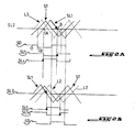
- FIG. 2A relates to the use case shown in FIG. 1 where it is necessary to determine the sign of the phase angle between the two phases L1 and L2.
- phase signals of normally sinusoidal shape are represented by signals evaluating in time linearly. Since in FIG. 1 the signal of the phase L2 serves as voltage reference by being applied to the reference terminals R constituting the internal mass of the apparatus, the signal SL2 of the phase L2 is shown to be constant and the representative signal ST earth is periodic and constitutes an alternating signal with respect to the reference signal SL2.
- the signal SL1 of the phase L1 applied via the capacitor 26 to the clock inputs H D and D type flip-flops 15 also constitute an alternating signal with respect to the reference signal SL2.
- the flip-flops 14 and 15 thus receive three signals, namely a first signal SL1 at the clock inputs H, a second signal formed by the signal SL2 serving as reference and applied to the reference input R and internal ground, and a signal third phase tracking signal of the second signal SR2 with respect to earth 8, which is positive or negative with respect thereto.
- This third signal is applied to the data inputs D of the flip-flops.
- FIG. 2A also shows the evolution of the SD signal. It can be seen that this signal represents a logic state 1 or 2 according to whether the third signal ST is positive or negative with respect to the reference signal SL2.
- FIG. 2A also illustrates the clock signals SL1 applied to the input H of the flip-flop 14 and the signal SL1i inverted by the inverter 27 with respect to the signal SL1 at the clock input H of the flip-flop 15.
- the method does not require the use of a flip-flop, namely the flip-flop 14, the flip-flop 15 constituting an additional advantage, as will be explained later.
- the Q output of the flip-flop 14 indicates the sign of the phase angle between the phase signal SL1 and the phase signal SL2.
- the sign of the phase angle of the signal SL1 with respect to the signal SL2 changes at the points A and B to become positive and negative and it is at these points A and B that the clock signal at the clock input H changes, showing at the output Q the logic states of the data input SD, which are different at points A and B.
- the logic state at the output Q determines whether or not the light 20 is illuminated or not, thereby signaling the phase sign and the direction of rotation between the phases L1 and L2 of the three-phase system.
- the flip-flop 15 receives an inverted clock signal with respect to the clock signal applied to the flip-flop 14, the logic state at its output Q is different compared to the output signal of the flip-flop 4.
- the two flip-flops 14 and 15 are provided to allow confirmation of the interpretation of the input signals.
- the two flip-flops would be in the same state and none of the lights 20, 21 would be activated.
- the inversion of the clock signals to the flip-flops 14 and 15 makes it possible to light a light in the direct direction of rotation and the other in the opposite direction of rotation.
- FIG. 2B illustrates the case where the first signal serving as clock signal to the flip-flops is the signal SL1 present on the phase L1 is the signal serving as a reference and the signal SL3 present on the phase L3.
- test apparatus in that an input is capacitively coupled with the ground, can be used, with the aid of the tracking circuit 29, to detect the presence of the phases in opposition to the neutral.
- This input circuit is thus common to the phase detection and the identification of the direction of rotation of the phases.
- the switch contact 24, in the form of a pushbutton is placed near the capacitive sensor element 6 of the ground signal, in order to force the user to place a finger on it. If the pushbutton is not closed, the excitation circuits of the lights 20, 21 are open and the lights are thus prevented from lighting up.
- the switch 24 also serves, on release, to reset the two latches 14 and 15 via a connection of its terminal connected to the circuits to the reset input Rz flip-flops in the manner shown in Figure 1.
Landscapes
- Physics & Mathematics (AREA)
- General Physics & Mathematics (AREA)
- Testing Of Short-Circuits, Discontinuities, Leakage, Or Incorrect Line Connections (AREA)
- Measuring Phase Differences (AREA)
- Indicating Or Recording The Presence, Absence, Or Direction Of Movement (AREA)
Claims (12)
- Verfahren zur Identifizierung der Drehrichtung zweier periodischer elektrischer Signale (SL1, SL2), die an zwei elektrischen Leitern (L1, L2) anliegen, insbesondere eines dreiphasigen Spannungssystems, durch das die Signale über die beiden Leiter (L1, L2) mittels zweier Drähte (3, 4) eines Testgeräts, die mit einem Erdungsanschluss (8) über den Abnehmer (7) des Geräts versehen sind, abgegriffen werden, und durch das die Drehrichtung ausgehend von den Informationen, die von den beiden Signalen übermittelt werden, bestimmt wird, wobei das eine der beiden Phasensignale (SL2) als Referenzspannung dient, das andere Phasensignal (SL1) phasenverschoben ist, um die durch den Erdungsanschluss über den Abnehmer verursachte Phasenverschiebung auszugleichen, dadurch gekennzeichnet, dass die Phasenverschiebung des anderen Signals durch eine Eingangsschaltung umgesetzt wird, die eine Kapazität (26) umfasst.
- Verfahren nach Anspruch 1, dadurch gekennzeichnet, dass die Drehrichtung während des Nulldurchgangs der Spannung, der zwischen den beiden Phasensignalen (SL1, SL2) besteht, bestimmt wird.
- Gerät zur Anwendung des Verfahrens nach einem der vorstehenden Ansprüche, wobei das Gerät einen als Referenz dienenden Probenahme-Draht des Phasensignals (SL2), einen Probenahme-Draht des anderen Phasensignals (SL1), einen Erdungsanschluss über den Abnehmer und mindestens eine Vorrichtung (14) umfasst, die dazu ausgelegt ist, ein repräsentatives Signal der Drehrichtung der Phasen in Abhängigkeit von dem als Referenz dienenden Signal (SL2), in Abhängigkeit von dem anderen Signal (SL1) nach der Phasenverschiebung und in Abhängigkeit von dem durch den Erdungsanschluss empfangenen Signal, zu erzeugen, dadurch gekennzeichnet, dass es eine Eingangsschaltung umfasst, die das andere Phasensignal (SL1) empfängt, und dass es eine Kapazität (26) zum Ausgleich der durch die Erdung über den Abnehmer verursachten Phasenverschiebung umfasst.
- Gerät nach Anspruch 3, dadurch gekennzeichnet, dass die oben genannte Vorrichtung einen Eingang (R) zum Empfangen des als Referenz dienenden Phasensignals (SL2), einen Eingang (H) zum Empfangen des anderen Signals (SL1) nach der Phasenverschiebung und einen Eingang (D) zum Empfangen eines repräsentativen Signals des Zeichens des Referenzsignals (SL2) bezüglich der Erdung (8) umfasst.
- Gerät nach Anspruch 3, dadurch gekennzeichnet, dass es einen Flip-Flop des Typs D (14) umfasst, der an seinem Referenzeingang das als Referenz dienende Phasensignal (SL2), an seinem Takteingang (H) das andere Phasensignal (SL1) nach der Phasenverschiebung und an seinem Dateneingang (D) ein repräsentatives Signal des Zeichens des Referenzsignals bezüglich der Erdung (8) empfängt, wobei der Status am Ausgang (Q) des Flip-Flops die Drehrichtung der Phasen angibt.
- Gerät nach einem der Ansprüche 3 bis 5, dadurch gekennzeichnet, dass es eine Vorrichtung (19) zur Anzeige der Drehrichtung der Phasen (L1, L2) umfasst.
- Gerät nach einem der Ansprüche 3 bis 6, dadurch gekennzeichnet, dass die Mittel zur Erdung über den Abnehmer des Geräts ein Metallelement im Inneren des Gerätegehäuses mit einem bestimmten Abstand zu dessen Innenwand (11) und einen Kontaktbereich (12) auf der Außenoberfläche des Gehäuses auf Höhe des Metallelements (10) umfassen, wobei das Gehäuse und der Abstand zwischen dem Metallelement (10) und der Innenwand (11) als Nichtleiter dienen.
- Gerät nach einem der Ansprüche 3 bis 7, dadurch gekennzeichnet, dass es eine Vorrichtung (29) zur Etablierung des Zeichens des Referenzsignals (SL2) bezüglich der Erdung (8) und zur Anwendung dieses Signals am Dateneingang D der Vorrichtung zur Etablierung der Drehrichtung (14) umfasst.
- Gerät nach Anspruch 8, dadurch gekennzeichnet, dass die vorstehend genannte Vorrichtung (29) dazu ausgelegt ist, die Gegenwart eines als Referenzphase dienenden Phasensignals (SL2) zu orten.
- Gerät nach Anspruch 9, dadurch gekennzeichnet, dass es einen in der Aktivierungsschaltung der Vorrichtung (19) zur Anzeige der Drehrichtung vorgesehenen Kontaktschalter (24) umfasst, der geschlossen ist, wenn der Abnehmer den Kontaktbereich (12) des Gerätegehäuses berührt.
- Gerät nach einem der Ansprüche 5 bis 10, dadurch gekennzeichnet, dass es einen zweiten Flip-Flop (15) des Typs D umfasst, der parallel zum ersten Flip-Flop (14) des Typs D angebracht ist, der jedoch an seinem Takteingang (H) das umgekehrte Phasensignal (SL1) empfängt, wobei dieser zweite Flip-Flop die Bestätigung des vom Flip-Flop (14) erhaltenen Ergebnisse ermöglicht.
- Gerät nach Anspruch 11, dadurch gekennzeichnet, dass eine Schaltung vom Typ OU "exklusiv" so zwischen den Flip-Flops und der Anzeige-Vorrichtung (19) angebracht ist, um jede fehlerhafte Anzeige zu verhindern.
Priority Applications (5)
| Application Number | Priority Date | Filing Date | Title |
|---|---|---|---|
| AT03291549T ATE370421T1 (de) | 2003-06-24 | 2003-06-24 | Verfahren und vorrichtung zur erkennung der drehrichtung zweier phasen in einem dreiphasenspannungssystem |
| DE60315619T DE60315619T2 (de) | 2003-06-24 | 2003-06-24 | Verfahren und Vorrichtung zur Erkennung der Drehrichtung zweier Phasen in einem Dreiphasenspannungssystem |
| EP03291549A EP1491904B1 (de) | 2003-06-24 | 2003-06-24 | Verfahren und Vorrichtung zur Erkennung der Drehrichtung zweier Phasen in einem Dreiphasenspannungssystem |
| ES03291549T ES2291599T3 (es) | 2003-06-24 | 2003-06-24 | Procedimiento y dispositivo de identificacion del sentido de rotacion de dos fases de un sistema de tension trifasico. |
| US10/873,637 US7337083B2 (en) | 2003-06-24 | 2004-06-23 | Process for identification of the direction of rotation of two periodic electrical signals at the same frequency |
Applications Claiming Priority (1)
| Application Number | Priority Date | Filing Date | Title |
|---|---|---|---|
| EP03291549A EP1491904B1 (de) | 2003-06-24 | 2003-06-24 | Verfahren und Vorrichtung zur Erkennung der Drehrichtung zweier Phasen in einem Dreiphasenspannungssystem |
Publications (2)
| Publication Number | Publication Date |
|---|---|
| EP1491904A1 EP1491904A1 (de) | 2004-12-29 |
| EP1491904B1 true EP1491904B1 (de) | 2007-08-15 |
Family
ID=33396055
Family Applications (1)
| Application Number | Title | Priority Date | Filing Date |
|---|---|---|---|
| EP03291549A Expired - Lifetime EP1491904B1 (de) | 2003-06-24 | 2003-06-24 | Verfahren und Vorrichtung zur Erkennung der Drehrichtung zweier Phasen in einem Dreiphasenspannungssystem |
Country Status (5)
| Country | Link |
|---|---|
| US (1) | US7337083B2 (de) |
| EP (1) | EP1491904B1 (de) |
| AT (1) | ATE370421T1 (de) |
| DE (1) | DE60315619T2 (de) |
| ES (1) | ES2291599T3 (de) |
Family Cites Families (18)
| Publication number | Priority date | Publication date | Assignee | Title |
|---|---|---|---|---|
| US3663956A (en) * | 1970-07-01 | 1972-05-16 | Ocean Data Equipment Corp | Digital phase measurement computation circuit |
| US4400667A (en) * | 1981-01-12 | 1983-08-23 | Sangamo Weston, Inc. | Phase tolerant bit synchronizer for digital signals |
| GB2100941B (en) * | 1981-06-08 | 1984-08-15 | Philips Electronic Associated | Waveform crossing detector |
| US4535459A (en) * | 1983-05-26 | 1985-08-13 | Rockwell International Corporation | Signal detection apparatus |
| JPS61191121A (ja) * | 1985-02-20 | 1986-08-25 | Hitachi Ltd | 発振装置 |
| US4845685A (en) * | 1987-07-17 | 1989-07-04 | Unisys Corporation | Digital phase-locked loop |
| BE1001712A7 (nl) * | 1988-05-11 | 1990-02-13 | Serrien Michel Patrick | Testapparaat voor drie-fazen draaizin. |
| KR920003598B1 (ko) * | 1988-12-22 | 1992-05-04 | 재단법인 한국전자통신 연구소 | Nrz비트 동기방식의 주파수 및 위상검출회로 |
| DE4002603C2 (de) * | 1990-01-30 | 1994-02-03 | Benning Elektrotechnik | Spannungsprüfer |
| KR930007716B1 (ko) * | 1990-07-20 | 1993-08-18 | 재단법인 한국전자통신연구소 | 비트 동기를 위한 디지틀 위상 검출기 |
| US5159279A (en) * | 1990-11-27 | 1992-10-27 | Dsc Communications Corporation | Apparatus and method for detecting out-of-lock condition in a phase lock loop |
| KR930007652B1 (ko) * | 1991-07-19 | 1993-08-14 | 한국전기 통신공사 | Cmi데이터 비트동기를 위한 위상검출기와 연동되어 동작하는 cmi/nrz복호기 |
| DE4134695A1 (de) * | 1991-10-21 | 1993-04-22 | Beha C Gmbh | Pruefgeraet zur anzeige elektrischer spannung |
| US5436598A (en) * | 1994-01-21 | 1995-07-25 | Calcomp Inc. | Phase lock loop circuit for signals periodically inverting in phase |
| KR970003097B1 (ko) * | 1994-12-02 | 1997-03-14 | 양승택 | 다단 제어구조를 갖는 고속 비트동기 장치 |
| US5799048A (en) * | 1996-04-17 | 1998-08-25 | Sun Microsystems, Inc. | Phase detector for clock synchronization and recovery |
| DE19653323C2 (de) * | 1996-12-20 | 2001-07-12 | Beha C Gmbh | Vorrichtung zur Bestimmung des Vorzeichens einer Phasenverschiebung zweier elektrischer Signale |
| DE29815829U1 (de) * | 1998-09-04 | 1999-03-18 | Steinel GmbH & Co KG, 33442 Herzebrock-Clarholz | Vorrichtung zur handbetätigten Messung elektrischer Signale |
-
2003
- 2003-06-24 EP EP03291549A patent/EP1491904B1/de not_active Expired - Lifetime
- 2003-06-24 ES ES03291549T patent/ES2291599T3/es not_active Expired - Lifetime
- 2003-06-24 AT AT03291549T patent/ATE370421T1/de active
- 2003-06-24 DE DE60315619T patent/DE60315619T2/de not_active Expired - Lifetime
-
2004
- 2004-06-23 US US10/873,637 patent/US7337083B2/en not_active Expired - Lifetime
Also Published As
| Publication number | Publication date |
|---|---|
| ATE370421T1 (de) | 2007-09-15 |
| EP1491904A1 (de) | 2004-12-29 |
| US7337083B2 (en) | 2008-02-26 |
| ES2291599T3 (es) | 2008-03-01 |
| US20050038617A1 (en) | 2005-02-17 |
| DE60315619T2 (de) | 2008-06-05 |
| DE60315619D1 (de) | 2007-09-27 |
Similar Documents
| Publication | Publication Date | Title |
|---|---|---|
| EP0427638B1 (de) | Leitungschnittstelle für ein Nachrichtenübertragungsnetz | |
| EP0062572B1 (de) | Kapazitives Tastenfeld mit gegen Störungen wirksamer Struktur | |
| FR2484637A1 (fr) | Appareil pour mesurer la quantite de carburant dans un reservoir | |
| FR2659764A1 (fr) | Micro-ordinateur et carte a circuits integres sans contact utilisant un tel micro-ordinateur. | |
| EP1456489B1 (de) | Vorrichtung zur detektion der anwesenheit eines benutzers, insbesondere für kraftfahrzeuge | |
| FR2993384A1 (fr) | Dispositif de detection de la presence d'un utilisateur, poignee de portiere comprenant ledit dispositif et procede de configuration de la poignee associee | |
| EP1491904B1 (de) | Verfahren und Vorrichtung zur Erkennung der Drehrichtung zweier Phasen in einem Dreiphasenspannungssystem | |
| FR2778464A1 (fr) | Dispositif de controle de l'antenne d'un systeme prevu dans un vehicule automobile, notamment un systeme de blocage de conduite | |
| FR2828286A1 (fr) | Dispositif de diagnostic pour une antenne | |
| FR2927108A1 (fr) | Dispositif de detection de toucher d'une poignee de porte de vehicule automobile | |
| EP0348259B1 (de) | System zur Auswertung von Signalen von linearen induktiven Weggebern | |
| EP2994920A1 (de) | Überzug zur abdeckung eines objekts, insbesondere eines kabels, zwecks erkennung und/oder ortung eines fehlers auf dessen oberfläche | |
| EP0866326B1 (de) | Installation zur Aufspürung und Ortung von Flüssigkeitsleckagen | |
| FR2730814A1 (fr) | Dispositif de surveillance de l'etat de fusibles de protection d'organes fonctionnels d'un vehicule automobile | |
| FR2556843A1 (fr) | Appareil de localisation de defauts resistifs dans des boucles de guidage | |
| FR2639435A3 (fr) | Transducteur de detection d'acceleration a effet capacitif | |
| FR2922371A1 (fr) | Dispositif de controle de connexion, et connecteurs munis d'un tel dispositif | |
| EP1468158B1 (de) | Fahrzeugtürgriff mit annäherungssensor | |
| EP0338881B1 (de) | Verfahren und Vorrichtung zur Signalrekonfiguration in einem differentiellen Nachrichtenübertragungsnetzwerk, insbesondere in einem Kraftfahrzeug | |
| FR2566137A2 (fr) | Dispositif de detection d'une cible magnetique dans une zone de proximite definie | |
| FR2944663A1 (fr) | Appareil, en particulier camera dentaire ou medicale, avec des unites d'alimentation et d'activation | |
| FR2670015A1 (fr) | Dispositif de mesure de l'intensite d'un courant dans un conducteur. | |
| FR2619632A1 (fr) | Dispositif de mesure de la valeur de crete d'une tension | |
| EP0524590A1 (de) | Einrichtung zur Demodulation von FSK-Signalen, mit Halbtakt-Aktualisierung | |
| EP0343083A1 (de) | Synchronisationsverlust-Detektionseinrichtung und deren Anwendung in einem Digitalübertragungsnetz |
Legal Events
| Date | Code | Title | Description |
|---|---|---|---|
| PUAI | Public reference made under article 153(3) epc to a published international application that has entered the european phase |
Free format text: ORIGINAL CODE: 0009012 |
|
| AK | Designated contracting states |
Kind code of ref document: A1 Designated state(s): AT BE BG CH CY CZ DE DK EE ES FI FR GB GR HU IE IT LI LU MC NL PT RO SE SI SK TR |
|
| AX | Request for extension of the european patent |
Extension state: AL LT LV MK |
|
| 17P | Request for examination filed |
Effective date: 20050412 |
|
| AKX | Designation fees paid |
Designated state(s): AT DE ES FR GB IT |
|
| GRAP | Despatch of communication of intention to grant a patent |
Free format text: ORIGINAL CODE: EPIDOSNIGR1 |
|
| GRAS | Grant fee paid |
Free format text: ORIGINAL CODE: EPIDOSNIGR3 |
|
| GRAA | (expected) grant |
Free format text: ORIGINAL CODE: 0009210 |
|
| AK | Designated contracting states |
Kind code of ref document: B1 Designated state(s): AT DE ES FR GB IT |
|
| REG | Reference to a national code |
Ref country code: GB Ref legal event code: FG4D Free format text: NOT ENGLISH |
|
| REF | Corresponds to: |
Ref document number: 60315619 Country of ref document: DE Date of ref document: 20070927 Kind code of ref document: P |
|
| GBT | Gb: translation of ep patent filed (gb section 77(6)(a)/1977) |
Effective date: 20071121 |
|
| REG | Reference to a national code |
Ref country code: ES Ref legal event code: FG2A Ref document number: 2291599 Country of ref document: ES Kind code of ref document: T3 |
|
| PLBE | No opposition filed within time limit |
Free format text: ORIGINAL CODE: 0009261 |
|
| STAA | Information on the status of an ep patent application or granted ep patent |
Free format text: STATUS: NO OPPOSITION FILED WITHIN TIME LIMIT |
|
| 26N | No opposition filed |
Effective date: 20080516 |
|
| PGFP | Annual fee paid to national office [announced via postgrant information from national office to epo] |
Ref country code: GB Payment date: 20150630 Year of fee payment: 13 |
|
| PGFP | Annual fee paid to national office [announced via postgrant information from national office to epo] |
Ref country code: AT Payment date: 20150626 Year of fee payment: 13 |
|
| PGFP | Annual fee paid to national office [announced via postgrant information from national office to epo] |
Ref country code: ES Payment date: 20150722 Year of fee payment: 13 Ref country code: DE Payment date: 20150831 Year of fee payment: 13 |
|
| PGFP | Annual fee paid to national office [announced via postgrant information from national office to epo] |
Ref country code: IT Payment date: 20150625 Year of fee payment: 13 |
|
| REG | Reference to a national code |
Ref country code: FR Ref legal event code: PLFP Year of fee payment: 14 |
|
| REG | Reference to a national code |
Ref country code: DE Ref legal event code: R119 Ref document number: 60315619 Country of ref document: DE |
|
| REG | Reference to a national code |
Ref country code: AT Ref legal event code: MM01 Ref document number: 370421 Country of ref document: AT Kind code of ref document: T Effective date: 20160624 |
|
| GBPC | Gb: european patent ceased through non-payment of renewal fee |
Effective date: 20160624 |
|
| PG25 | Lapsed in a contracting state [announced via postgrant information from national office to epo] |
Ref country code: DE Free format text: LAPSE BECAUSE OF NON-PAYMENT OF DUE FEES Effective date: 20170103 |
|
| PG25 | Lapsed in a contracting state [announced via postgrant information from national office to epo] |
Ref country code: AT Free format text: LAPSE BECAUSE OF NON-PAYMENT OF DUE FEES Effective date: 20160624 Ref country code: GB Free format text: LAPSE BECAUSE OF NON-PAYMENT OF DUE FEES Effective date: 20160624 |
|
| REG | Reference to a national code |
Ref country code: FR Ref legal event code: PLFP Year of fee payment: 15 |
|
| PG25 | Lapsed in a contracting state [announced via postgrant information from national office to epo] |
Ref country code: IT Free format text: LAPSE BECAUSE OF NON-PAYMENT OF DUE FEES Effective date: 20160624 |
|
| PG25 | Lapsed in a contracting state [announced via postgrant information from national office to epo] |
Ref country code: ES Free format text: LAPSE BECAUSE OF NON-PAYMENT OF DUE FEES Effective date: 20160625 |
|
| REG | Reference to a national code |
Ref country code: FR Ref legal event code: PLFP Year of fee payment: 16 |
|
| REG | Reference to a national code |
Ref country code: ES Ref legal event code: FD2A Effective date: 20180626 |
|
| PGFP | Annual fee paid to national office [announced via postgrant information from national office to epo] |
Ref country code: FR Payment date: 20200625 Year of fee payment: 18 |
|
| PG25 | Lapsed in a contracting state [announced via postgrant information from national office to epo] |
Ref country code: FR Free format text: LAPSE BECAUSE OF NON-PAYMENT OF DUE FEES Effective date: 20210630 |