EP0849839A1 - Connecteur électrique - Google Patents
Connecteur électrique Download PDFInfo
- Publication number
- EP0849839A1 EP0849839A1 EP97121160A EP97121160A EP0849839A1 EP 0849839 A1 EP0849839 A1 EP 0849839A1 EP 97121160 A EP97121160 A EP 97121160A EP 97121160 A EP97121160 A EP 97121160A EP 0849839 A1 EP0849839 A1 EP 0849839A1
- Authority
- EP
- European Patent Office
- Prior art keywords
- connector housings
- elastic portion
- jig
- connector
- short
- Prior art date
- Legal status (The legal status is an assumption and is not a legal conclusion. Google has not performed a legal analysis and makes no representation as to the accuracy of the status listed.)
- Withdrawn
Links
- 238000001514 detection method Methods 0.000 claims description 41
- 230000005489 elastic deformation Effects 0.000 abstract description 4
- 238000003780 insertion Methods 0.000 description 24
- 230000037431 insertion Effects 0.000 description 24
- 238000010276 construction Methods 0.000 description 17
- 230000000694 effects Effects 0.000 description 6
- 238000000034 method Methods 0.000 description 5
- 238000005452 bending Methods 0.000 description 1
- 230000015572 biosynthetic process Effects 0.000 description 1
- 230000001419 dependent effect Effects 0.000 description 1
- 230000013011 mating Effects 0.000 description 1
- 230000007246 mechanism Effects 0.000 description 1
- 238000000465 moulding Methods 0.000 description 1
Images





Classifications
-
- H—ELECTRICITY
- H01—ELECTRIC ELEMENTS
- H01R—ELECTRICALLY-CONDUCTIVE CONNECTIONS; STRUCTURAL ASSOCIATIONS OF A PLURALITY OF MUTUALLY-INSULATED ELECTRICAL CONNECTING ELEMENTS; COUPLING DEVICES; CURRENT COLLECTORS
- H01R13/00—Details of coupling devices of the kinds covered by groups H01R12/70 or H01R24/00 - H01R33/00
- H01R13/64—Means for preventing incorrect coupling
- H01R13/641—Means for preventing incorrect coupling by indicating incorrect coupling; by indicating correct or full engagement
-
- H—ELECTRICITY
- H01—ELECTRIC ELEMENTS
- H01R—ELECTRICALLY-CONDUCTIVE CONNECTIONS; STRUCTURAL ASSOCIATIONS OF A PLURALITY OF MUTUALLY-INSULATED ELECTRICAL CONNECTING ELEMENTS; COUPLING DEVICES; CURRENT COLLECTORS
- H01R13/00—Details of coupling devices of the kinds covered by groups H01R12/70 or H01R24/00 - H01R33/00
- H01R13/66—Structural association with built-in electrical component
- H01R13/70—Structural association with built-in electrical component with built-in switch
- H01R13/703—Structural association with built-in electrical component with built-in switch operated by engagement or disengagement of coupling parts, e.g. dual-continuity coupling part
Definitions
- the present invention relates to a connector provided with a locking means for locking a pair of connector housings in their engaged state.
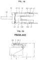
- FIG. 20 A connector of this type is shown in FIG. 20.
- a female connector housing 1 is formed with an elastic portion 2, and a receptacle of a male connector housing 3 is formed with a lock hole 5.
- a projection 2A thereof is engaged with the lock hole 5.
- the connector housings 1, 3 are locked so as to be disengageable from each other.
- the connector housings 1, 3 When the connector housings 1, 3 are to be disengaged, an operable portion 2B formed on the elastic portion 2 is pushed by finger to deform the elastic portion 2, which is then disengaged from the lock hole 5. In this state, the connector housings 1, 3 are separated from each other. In such a connector, in order to improve operability, the connector housings 1, 3 can be locked only by being engaged with each other and can be easily unlocked only by manually operating the operable portion 2B exposed from the receptacle.
- a method may be considered which locks connector housings while fixing with a screw or a bolt after the connector housings are engaged.
- the locking operation is very cumbersome.
- the present invention was developed in view of the above problem and an object thereof is to provide a connector which can be easily locked, but cannot be easily unlocked.
- a connector comprising:
- At least one of the connector housings is provided with a cover for substantially covering the locking means such that the locking means cannot be directly unlocked by hand or finger or without the use of an auxiliary tool.
- the connector comprises a pair of connector housings engageable with each other, and a locking means for locking the connector housings in their engaged state as the connector housings are engaged, wherein the connector housing is provided with a cover for covering the locking means such that the locking means cannot be directly unlocked by hand or finger.
- an unlock detecting means is provided to electrically shut off electric circuits by detecting the unlocking of the connector housings, wherein preferably the locking means is unlockable only by the operation of a jig and the unlock detecting means electrically shuts off the electric circuits by detecting the unlocking by the jig.
- a connector comprising:
- the connector housings cannot be easily unlocked by hand or finger while being engaged and locked.
- the connector housings are separated by pulling them away from each other.
- the unlocking by the jig is detected by the unlock detecting means and the electric circuits are electrically shut off.
- the unlock detecting means comprises a switch element including at least one pair of detection fittings provided on the locking means and at least one short-circuiting fitting for short-circuiting the pair of detection fittings upon the unlocking of the connector housings, wherein the at least one short-circuiting fitting is preferably provided on the jig for short-circuiting the pair of detection fittings upon the unlocking by the jig.
- the unlock detecting means preferably comprises a switch element including a pair of detection fittings provided on the locking means and a short-circuiting fitting provided on the jig for short-circuiting the pair of detection fittings upon the unlocking by the jig.
- the short-circuiting fitting provided on the jig short-circuits the pair of detection fittings. Thereby, the unlocking by the jig is detected and the electric circuits are electrically shut off.
- the unlock detecting means comprises a switch element including at least one pair of detection fittings provided on the locking means of one connector housing and at least one short-circuiting fitting provided on the locking means of the other connector housing, the pair of detection fittings being short-circuited by the short-circuiting fittings in a locked state, and wherein the short-circuiting of the pair of detection fittings is preferably released by the unlocking by the jig.
- the short-circuiting fitting is disengaged from the pair of detection fittings to release the short-circuited state. Thereby, the unlocking by the jig is detected and the electric circuits are electrically shut off.
- FIGS. 1 to 3 a first embodiment of the invention is described with reference to FIGS. 1 to 3.
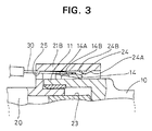
- a connector according to this embodiment is provided with a male connector housing 10, a female connector housing 20 and a locking means for locking the connector housings 10, 20 in their engaged state.
- the male connector housing 10 includes a tubular engaging portion 11 projecting forward, and a substantially bar-shaped male terminal fitting 12 projecting inside the engaging portion 11.
- the male terminal fitting 12 is connected with a wire 13 which comes out through the rear end surface of the male connector housing 10.
- An elastic portion 14 which substantially constructs the locking means is formed on the outer surface of the engaging portion 11 of the male connector housing 10.
- the elastic portion 14 is shaped such that it substantially axially extends, preferably upward from its fixed end in vicinity of a front end of the engaging portion 11 and is then bent so that its free end extends in the longitudinal direction, preferably in a direction of engagement of the male/female connector housings 10, 20, e.g. backward.
- the elastic portion 14 is elastically deformable preferably in substantially radial direction.
- a jig insertion portion 14A formed e.g. by cutting away the upper surface over the front surface to form a downward sloped surface to the front.
- a jig 30 for disengaging the elastic portion 14 and a lock projection 24 is insertable or fittable into the jig insertion portion 14A.
- the female connector housing 20 includes a tubular hood or receptacle 21 projecting forward.
- a tubular female terminal fitting 22 engageable with the male terminal fitting 12 projects inside the receptacle 21.
- the female terminal fitting 22 is connected with a wire 23 which comes out through the rear end surface of the female connector housing 20.
- the receptacle 21 substantially covers the engaging portion 11 and the elastic portion 14 at least when the male and female connector housings 10, 20 are engaged.
- the receptacle 21 is comprised of an arcuate portion 21A which is so formed as to conform to the outer surface of the engaging portion 11 and a substantially box-shaped covering portion 21B in which the elastic portion 14 can be accommodated.
- a clearance between the covering portion 21B and the outer surface of the engaging portion 11 when the covering portion 21B covers the elastic portion 14 is set small e.g. such that a finger, not to mention a hand cannot be inserted into this clearance.
- the lock projection 24 which is inwardly projecting and engageable with the elastic portion 14 and substantially constructs the locking means.
- This lock projection 24 is comprised of a slanted surface 24A which faces the elastic portion 14 while the connector housings 10, 20 are being engaged and a lock surface 24B which engages the leading end surface of the elastic portion 14 when the engagement of the connector housings 10, 20 is completed.
- the lock projection 24 is located in a position where it can be aligned with the jig insertion portion 14A of the elastic portion 14 and has a narrower width than the jig insertion portion 14A. Accordingly, while the connector housings 10, 20 are being engaged, the lock projection 24 enters the jig insertion portion 14A to face a slanted surface 14B.
- a mold withdrawal hole 25 used to withdraw a mold (not shown) for forming the lock projection 24.
- This hole 25 faces the jig insertion portion 14A of the elastic portion 14 when the connector housings 10, 20 are locked.
- the narrow jig 30 is inserted into the mold withdrawal hole 25, its leading end reaches the jig insertion portion 14A.
- the receptacle 21 is substantially fitted around the engaging portion 11, and the connector housings 10, 20 are pressed or moved into each other while being positioned with respect to circumferential direction by a positioning means (not shown) constructed by, e.g. a projection and a groove or by forming the male/female connector housing 10, 20 with a non-circular cross section.
- a positioning means constructed by, e.g. a projection and a groove or by forming the male/female connector housing 10, 20 with a non-circular cross section.
- the lock projection 24 enters the jig insertion portion 14A and comes into contact with the slanted surface 14B. Due to a pressing force acting on the slanted surface 14B, the elastic portion 14 undergoes such an elastic deformation as to move away from the lock projection 24.
- the lock projection 24 is disengaged from the upper surface of the elastic portion 14, which is then elastically restored substantially to its original position. As a result, as shown in FIG. 2, the lock surface 24B of the lock projection 24 and the leading end surface of the elastic portion 14 are locked. The connector housings 10, 20 are locked in their engaged state by the engagement of the lock projection 24 and the elastic portion 14.
- the engaged elastic portion 14 and lock projection 24 are concealed by the covering portion 21B. Since the inside of the covering portion 21B is narrow, an operator cannot directly touch the elastic portion 14 with his hand or finger. Accordingly, it is impossible for the operator to unlock the connector housings 10, 20 by operating the elastic portion 14 with his hand or finger.
- the jig 30 is inserted through the mold withdrawal hole 25 to come into contact with the slanted surface 14B of the jig insertion portion 14A, and is operated to lower the jig insertion portion 14A. Then, as shown in FIG. 3, the elastic portion 14 is deformed away from the lock projection 24 to unlock the connector housings 10, 20. If the connector housings 10, 20 are slightly moved away from each other in this state, the lock projection 24 comes into contact with the upper surface of the elastic portion 14. Thereafter, the jig 30 is withdrawn and the connector housings 10, 20 are or can be separated from each other.
- the connector housings 10, 20 are locked at once only by being engaged with each other, improving operability. Further, since the connector housings 10, 20 cannot be unlocked by hand or finger, an inadvertent disengagement thereof can be securely prevented.
- the strength of the covering portion 21B is higher as compared to a case where a jig insertion hole separate from the mold withdrawal hole 25 is formed, e.g. in the upper surface of the covering portion 21B.
- the elastic portion 14 is formed with the cut-away portion (jig insertion portion 14A) and the lock projection 24 is formed with the slanted surface 24A, an excessive deformation of the elastic portion 14 while the connector housings 10, 20 are being engaged and disengaged can be prevented.
- the locking means of this embodiment is different from that of the first embodiment. Since the other construction is same or similar as the first embodiment, no description is given on the structure, action and effects thereof by identifying it by the same reference numerals.
- the locking means of the second embodiment is comprised of an elastic portion 44 formed on a male connector housing 40 and a lock projection 54 formed on a female connector housing 50.
- the elastic portion 44 is formed on the outer surface of an engaging portion 41 and is shaped such that it extends upward from its fixed end at the rear end of the engaging portion 41 and is then bent so that its free end extends in a longitudinal direction, preferably toward the female connector housing 50, e.g. forward.
- a substantially middle part of the elastic portion 44 with respect to its width direction is e.g. cut away except the front end.
- the front end of this cut-away portion 44A acts as a lock surface 44B engageable with the lock projection 54.
- a cover 45 for substantially covering the elastic portion 44 is integrally or unitarily formed.
- the cover 45 preferably has a substantially rectangular shape having open front and rear surfaces.
- a hood or receptacle 51 is comprised of a semicircular portion 51A fittable around the engaging portion 41 and a substantially rectangular covering portion 51B fittable substantially around the cover 45.
- the lock projection 54 projects forward from the rear surface of the cover portion 51B, and a protuberance 55 is formed at the projecting end of the lock projection 54.
- the protuberance 55 includes a lock surface 55A engageable with the lock surface 44B of the elastic portion 44 and a slanted surface 55B which can push the leading end of the elastic portion 44 in a radial direction, preferably away from the male connector housing 40, e.g. upward.
- a jig insertion hole 56 used to insert a jig 60 for an unlocking purpose. It should be noted that this jig insertion hole 56 also acts as a mold withdrawal hole formed when the protuberance 55 is formed.
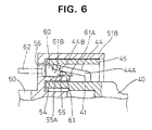
- the jig 60 is comprised of a pair of forward projecting displacing or deforming (preferably push-up) portions 61 and a backward projecting narrow grip 62.
- the leading end of each push-up portion 61 has its upper surface slanted to form a slip portion 61A, and the upper surface of the base portion of the deforming or push-up portion 61 is gradually thickened to form an arcuate surface, thereby forming a deforming or push-up surface 61B.
- the semicircular portion 51A and the covering portion 51B of the receptacle 51 are fitted substantially around the engaging portion 41 and the cover 45, and the connector housings 40, 50 are pushed into each other while being positioned along circumferential direction. Then, the lock projection 54 enters a clearance between the engaging portion 41 and the elastic portion 44, and the slanted surface 55B comes into contact with the leading edge of the elastic portion 44 preferably from below. Due to a pressing force of the slanted surface 55B, the elastic portion 44 is elastically deformed so as to move onto the protuberance 55. When the connector housings 40, 50 are properly engaged, the elastic portion 44 is disengaged from the protuberance 55 and is elastically restored substantially to its original position. As a result, as shown in FIG. 5, the lock surface 55A of the protuberance 55 and the lock surface 44B of the elastic portion 44 are engaged to lock the connector housings 40, 50 in their engaged state.
- the engaged elastic portion 44 and protuberance 55 are substantially concealed by the cover 45 and the covering portion 51B. Since the inside of the cover 45 and the covering portion 51B is narrow, an operator cannot directly touch the elastic portion 44 with his hand or finger. Accordingly, it is impossible for the operator to unlock the connector housings 40, 50 by operating the elastic portion 44 with his hand or finger.
- the jig 60 is inserted into the jig insertion hole 56 to cause the slip portions 61A to slip under the elastic portion 44, and is then further inserted. Then, the push-up surface 61B comes into contact with the lower edge of the leading end of the elastic portion 44, thereby pushing up the elastic portion 44 along its arcuate surface. As a result, the elastic portion 44 is disengaged from the protuberance 55 to unlock the connector housings 40, 50 as shown in FIG. 6. Thereafter, the connector housings 40, 50 are separated from each other in this state.
- the connector housings 40, 50 are locked at once only by being engaged with each other, improving operability. Further, since the connector housings 40, 50 cannot be unlocked by hand or finger, an inadvertent disengagement thereof can be securely prevented.
- the elastic portion 44 is covered by the cover 45 while the connector housings 40, 50 are separated from each other. This prevents the elastic portion 44 from being disadvantageously deformed upon contact with an other male connector housing 40 during the keeping and/or transportation.
- the third embodiment differs from the first embodiment in the construction of the connector housings.
- the connector according to the first embodiment is of one-contact type in which the male connector housing 10 and the female connector housing 20 are provided with the single male terminal fitting 12 and the signal female terminal fitting 22, respectively
- the one according to the third embodiment is of two-contact type in which male and female connector housings are provided with two male terminal fittings (not shown) and two female terminal fittings (not shown), respectively.
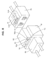
- a male connector housing 70 and a female connector housing 75 have a rectangular shape as a whole.
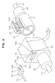
- an elastic portion 14 having the same or similar construction as that of the first embodiment is integrally formed.
- a hood or receptacle 71 of the male connector housing 70 is provided with a covering portion 72 for accommodating the elastic portion 14, and a lock projection 24 having the same construction as that of the first embodiment is formed on the ceiling surface of the covering portion 72.
- the fourth embodiment differs from the second embodiment in the construction of the connector housings.
- the connector according to the second embodiment is of one-contact type in which the male connector housing 40 and the female connector housing 50 are provided with the single male terminal fitting 12 and the signal female terminal fitting 22, respectively
- the one according to the fourth embodiment is of two-contact type in which male and female connector housings are provided with two male terminal fittings (not shown) and two female terminal fittings (not shown), respectively.
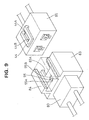
- a male connector housing 80 and a female connector housing 85 have a rectangular shape as a whole.
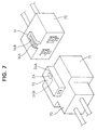
- an elastic portion 44 and a cover 45 having the same or similar construction as those of the second embodiment are integrally or unitarily formed.
- a hood or receptacle 81 of the male connector housing 80 is provided with a covering portion 82 engageable with the cover 45, and a lock projection 54 having the same or similar construction as that of the second embodiment is formed on the rear end surface of the covering portion 82.
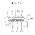
- the fifth embodiment differs from the fourth embodiment in the construction of the locking means.
- a hood or receptacle 83 has preferably such a substantially rectangular shape that only the female connector housing 85 can be fitted thereinto, and a covering portion 84 having open front and rear surfaces is formed on the upper surface. Inside the covering portion 84, a protuberance 55 projecting from the outer surface of the receptacle 83 is formed.
- This protuberance 55 has the same or similar construction as the protuberance 55 formed at the leading end of the lock projection 54 according to the fourth embodiment, and has a lock surface 55A and a slanted surface 55B. Further, a notch 83A is formed in the upper surface of the receptacle 83 in order to avoid the interference with the base end of the elastic portion 44.
- FIGS. 11 to 14 a sixth embodiment of the invention is described with reference to FIGS. 11 to 14.
- the sixth embodiment differs from the first embodiment in the provision of the unlock detecting means. Since the other construction is same or similar as the first embodiment, no description is given on the structure, action and effects thereof by identifying it by the same reference numerals.
- the male and female side wires 13, 23 are, for example, connected with electric circuits (not shown) such as high voltage circuits for charging in an electric automotive vehicle. These electric circuits are connected with an unlock detecting means for detecting the unlocking e.g. by the jig 30 to cut off a power application to the electric circuits and a self-maintaining circuit (not shown) for maintaining an electrically shut off state once the power application is cut off.
- electric circuits such as high voltage circuits for charging in an electric automotive vehicle.
- These electric circuits are connected with an unlock detecting means for detecting the unlocking e.g. by the jig 30 to cut off a power application to the electric circuits and a self-maintaining circuit (not shown) for maintaining an electrically shut off state once the power application is cut off.
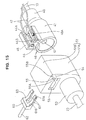
- the unlock detecting means is comprised of a switch element including a short-circuiting fitting 16 and a pair of detection fittings 26.
- the short-circuiting fitting 16 is embedded in the leading end of the elastic portion 14 of the male connector housing 10 in such a manner that it is substantially in flush with the upper surface of this leading end.
- the short-circuiting fitting 16 and the elastic portion 14 are made integral e.g. by insert molding.
- the pair of detection fittings 26 are so mounted as to be substantially in flush with the ceiling surface of the covering portion 21B preferably by substantially fitting the opposite ends thereof in mount grooves 28 formed there.
- Detection wires 27 connected with wire connection portions 26B of the respective detection fittings 26 are pulled out preferably through the mold withdrawal hole 25 to extend along the outer surface of the female connector housing 20 and along the wires 23 projecting from the rear end of the female connector housing 20, and are connected with the electric circuit. It is desirable to protect portions of the detection wires 27 exposed from the covering portion 21 by a cover or like means.
- each detection fitting 26 is formed with a contact portion 26A projecting from the ceiling surface of the covering portion 21B.
- the short-circuiting fitting 16 is located in the vicinity, preferably substantially above the detection fittings 26 when the elastic portion 14 and the lock projection 24 are locked.
- the contact portions 26A elastically touch the short-circuiting fitting 16 due to an elastic restoring force of the elastic portion 14, with the result that the detection fittings 26 are short-circuited by the short-circuiting fitting 16.
- the switch element is on and the electric circuit is electrically on.
- the short-circuiting of the detection fittings 26 is released by the unlocking by means of the jig 30, the switch element is turned off and the unlock detecting means detects the unlocking by the jig 30 to shut off the electric circuit.
- the receptacle 21 is fitted around the engaging portion 11, and the connector housings 10, 20 are pressed into each other while being positioned with respect to circumferential direction by a positioning means (not shown) constructed by, e.g. a projection and a groove. Then, the lock projection 24 enters the jig insertion portion 14A and comes into contact with the slanted surface 14B. Due to a pressing force acting on the slanted surface 14B, the elastic portion 14 undergoes such an elastic deformation as to move away from the lock projection 24. When the connector housings 10, 20 are properly engaged, the lock projection 24 is disengaged from the upper surface of the elastic portion 14, which is then elastically restored to its original position. As a result, as shown in FIG. 12, the lock surface 24B of the lock projection 24 and the leading end surface of the elastic portion 14 are locked. The connector housings 10, 20 are locked in their engaged state by the engagement of the lock projection 24 and the elastic portion 14.
- the engaged elastic portion 14 and lock projection 24 are concealed by the covering portion 21B. Since the inside of the covering portion 21B is narrow, an operator cannot directly touch the elastic portion 14 with his hand or finger. Accordingly, it is impossible for the operator to unlock the connector housings 10, 20 by operating the elastic portion 14 with his hand or finger.
- the jig 30 is inserted through the mold withdrawal hole 25 to come into contact with the slanted surface 14B of the jig insertion portion 14A, and is operated to lower the jig insertion portion 14A. Then, as shown in FIG. 13, the elastic portion 14 is deformed away from the lock projection 24 to unlock the connector housings 10, 20.
- the short-circuiting fitting 16 moves away from the detection fittings 26 to release the short-circuited state thereof, and the switch element is turned off. Thereupon, the unlocking by the jig 30 is detected and the electric circuit is electrically shut off.
- the connector housings 10, 20 are locked at once only by being engaged with each other, improving operability. Further, since the connector housings 10, 20 cannot be unlocked by hand or finger, an inadvertent disengagement thereof can be securely prevented. Further, the unlocking by the jig 30 is detected to electrically shut off the electric circuit. Thus, there is no likelihood that an arc is generated while the male and female terminal fittings 12, 22 are separated.
- the strength of the covering portion 21B is higher as compared to a case where a jig insertion hole separate from the mold withdrawal hole 25 is formed, e.g. in the upper surface of the covering portion 21B.
- the elastic portion 14 is formed with the cut-away portion (jig insertion portion 14A) and the lock projection 24 is formed with the slanted surface 24A, an excessive deformation of the elastic portion 14 while the connector housings 10, 20 are being engaged and disengaged can be prevented.
- the seventh embodiment differs from the sixth embodiment in the construction of the locking means and the unlock detecting means.
- the seventh embodiment differs from the second embodiment in the provision of the unlock detecting means. Since the other construction is same or similar as the second embodiment, no description is given on the structure, action and effects thereof by identifying it by the same reference numerals.
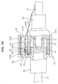
- the unlock detecting means is comprised of a switch element including a pair of detection fittings 46 provided on the elastic portion 44 and a short-circuiting fitting 63 provided on the jig 60.
- the detection fittings 46 are formed e.g. by bending the leading ends of plate members upward, extend substantially along the lower surface and the front end surface of the elastic portion 44 and the corner portions between these surfaces and are spaced apart to be positioned on the opposite sides of the cut-away portion 44A.
- a wire connecting portion 46A of each detection fitting 46 is formed to stand upright outside the elastic portion 44.
- Detection wires 47 connected with the wire connecting portions 46A are pulled out through an opening formed in a rear part of the cover 45, are preferably arranged to extend substantially along the outer surface of the male connector housing 40 and along the wire 13 projecting from the rear end of the male connector housing 40, and are connected with an electric circuit (not shown). It is desirable to protect portions of the detection wires 47 exposed from the covering portion 51B by a cover or like means.
- the short-circuiting fitting 63 is preferably a plate having a substantially forked leading end and is mounted along the upper surface of the deforming or push-up portion 61 of the jig 60.
- the unlocking is performed by causing the jig 60 to slip substantially under the elastic portion 44, the short-circuiting fitting 63 comes into contact with both detection fittings 46 to short-circuit them.
- the switch element is off when the detection fittings 46 are in their nonconductive state.
- the switch element is turned on and the unlocked state is detected, with the result that the electric circuit is electrically shut off.
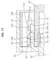
- the semicircular portion 51A and the covering portion 51B of the receptacle 51 are fitted around the engaging portion 41 and the cover 45, and the connector housings 40, 50 are pushed into each other while being positioned along circumferential direction. Then, the lock projection 54 enters a clearance between the engaging portion 41 and the elastic portion 44, and the slanted surface 55B comes into contact with the leading edge of the elastic portion 44 from below. Due to a pressing force of the slanted surface 55B, the elastic portion 44 is elastically deformed so as to move onto the protuberance 55. When the connector housings 40, 50 are properly engaged, the elastic portion 44 is disengaged from the protuberance 55 and is elastically restored to its original position. As a result, as shown in FIG. 17, the lock surface 55A of the protuberance 55 and the lock surface 44B of the elastic portion 44 are engaged to lock the connector housings 40, 50 in their engaged state.
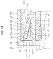
- the jig 60 is inserted into the jig insertion hole 56 to cause the slip portions 61A to slip under the elastic portion 44, and is then further inserted. Then, the short-circuiting fitting 63 comes into contact with the lower edges of the leading ends of a pair of detection fittings 46 mounted on the elastic portion 44, thereby pushing up the elastic portion 44 along its arcuate surface 61B. As a result, the elastic portion 44 is disengaged from the protuberance 55 to unlock the connector housings 40, 50 as shown in FIG. 18.
- the short-circuiting fitting 63 short-circuits the detection fittings 46, thereby turning the switch element on. As a result, the unlocking by the jig 60 is detected and the electric circuit is electrically shut off.
- the connector housings 40, 50 are slightly pulled away from each other in the unlocked state by the jig 60, the leading end of the elastic portion 44 moves over the protuberance 55. Accordingly, the connector housings 40, 50 are separated from each other by withdrawing the jig 60.
- the connector housings 40, 50 are locked at once only by being engaged with each other, improving operability. Further, since the connector housings 40, 50 cannot be unlocked by hand or finger, an inadvertent disengagement thereof can be securely prevented. Further, since the electric circuit is electrically shut off upon detecting the unlocking by the jig 60, there is no likelihood that a discharge phenomenon occurs while the male and female terminal fittings 12, 22 are separated from each other.
- the elastic portion 44 is covered by the cover 45 while the connector housings 40, 50 are separated from each other. This prevents the elastic portion 44 from being disadvantageously deformed upon contact with an other male connector housing 40 during the keeping and/or transportation.
Landscapes
- Details Of Connecting Devices For Male And Female Coupling (AREA)
Applications Claiming Priority (4)
| Application Number | Priority Date | Filing Date | Title |
|---|---|---|---|
| JP321878/96 | 1996-12-02 | ||
| JP32187896A JPH10162896A (ja) | 1996-12-02 | 1996-12-02 | コネクタ |
| JP327314/96 | 1996-12-06 | ||
| JP32731496A JPH10172664A (ja) | 1996-12-06 | 1996-12-06 | コネクタ |
Publications (1)
| Publication Number | Publication Date |
|---|---|
| EP0849839A1 true EP0849839A1 (fr) | 1998-06-24 |
Family
ID=26570621
Family Applications (1)
| Application Number | Title | Priority Date | Filing Date |
|---|---|---|---|
| EP97121160A Withdrawn EP0849839A1 (fr) | 1996-12-02 | 1997-12-02 | Connecteur électrique |
Country Status (2)
| Country | Link |
|---|---|
| US (1) | US5984705A (fr) |
| EP (1) | EP0849839A1 (fr) |
Cited By (12)
| Publication number | Priority date | Publication date | Assignee | Title |
|---|---|---|---|---|
| WO2002075859A1 (fr) * | 2001-03-20 | 2002-09-26 | Reichle & De-Massari Ag | Dispositif de securite pour connecteur male |
| EP1077511A3 (fr) * | 1999-08-17 | 2003-11-19 | Sumitomo Wiring Systems, Ltd. | Connecteur électrique |
| DE10306275A1 (de) * | 2003-02-14 | 2004-08-26 | Delphi Technologies, Inc., Troy | Steckverbinder |
| EP1762871A1 (fr) * | 2005-09-12 | 2007-03-14 | Reichle & De-Massari AG | Système de connecteur sécurisé |
| EP2672575A4 (fr) * | 2011-02-04 | 2014-07-23 | Fujikura Ltd | Assemblage de connecteur |
| DE102007003375B4 (de) * | 2007-01-23 | 2014-09-18 | Tyco Electronics Amp Gmbh | Elektrische Steckverbindung |
| CN105988165A (zh) * | 2015-02-16 | 2016-10-05 | 罗森伯格亚太电子有限公司 | 多芯光纤连接器 |
| EP2301117B1 (fr) * | 2008-05-09 | 2017-09-13 | Yamaichi Electronics Deutschland GmbH | Système de connecteurs, utilisation et procédé |
| US20220302643A1 (en) * | 2021-03-19 | 2022-09-22 | Tyco Electronics (Shanghai) Co. Ltd. | Connector and Connector Assembly |
| US12107366B2 (en) | 2021-03-19 | 2024-10-01 | Tyco Electronics (Shanghai) Co. Ltd. | Connector and connector assembly |
| US12170425B2 (en) | 2021-03-19 | 2024-12-17 | Tyco Electronics (Shanghai) Co., Ltd. | Connector and connector assembly |
| US12224528B2 (en) | 2021-03-19 | 2025-02-11 | Tyco Electronics (Shanghai) Co. Ltd. | Connector and connector assembly |
Families Citing this family (23)
| Publication number | Priority date | Publication date | Assignee | Title |
|---|---|---|---|---|
| US6537232B1 (en) | 1997-05-15 | 2003-03-25 | Regents Of The University Of Minnesota | Intracranial pressure monitoring device and method for use in MR-guided drug delivery |
| JP3674521B2 (ja) * | 2001-03-07 | 2005-07-20 | 住友電装株式会社 | コネクタ |
| JP3863732B2 (ja) * | 2001-05-16 | 2006-12-27 | 矢崎総業株式会社 | コネクタの組立方法および組立装置 |
| EP1369959B1 (fr) * | 2002-06-06 | 2007-10-24 | Sumitomo Wiring Systems, Ltd. | Un connecteur, un outil de désengagement et une méthode |
| JP4292803B2 (ja) * | 2003-01-09 | 2009-07-08 | 住友電装株式会社 | 係止解除用治具 |
| US20060040564A1 (en) * | 2004-08-19 | 2006-02-23 | Morrison David S | Block-out cover and removal tool |
| US7437819B1 (en) * | 2006-10-19 | 2008-10-21 | The United States Of America As Represented By The Secretary Of The Navy | Method for making under water connector |
| JP4947648B2 (ja) * | 2007-06-18 | 2012-06-06 | Smk株式会社 | コネクタ |
| US7806706B2 (en) * | 2007-07-03 | 2010-10-05 | Panduit Corp. | Plug locking assembly and system |
| US7632125B2 (en) * | 2007-08-17 | 2009-12-15 | Panduit Corp. | Plug locking assembly |
| CN101640340B (zh) * | 2008-07-29 | 2012-07-04 | Smk株式会社 | 连接器 |
| JP4820421B2 (ja) * | 2009-01-13 | 2011-11-24 | ホシデン株式会社 | コネクタ |
| US7993063B2 (en) * | 2009-03-16 | 2011-08-09 | Panduit Corp. | Block-out device for fiber optic adapter |
| US8224146B2 (en) * | 2010-02-05 | 2012-07-17 | Panduit Corp. | Block-out device for fiber optic adapter |
| DE202011000739U1 (de) * | 2011-03-31 | 2012-07-05 | Weidmüller Interface GmbH & Co. KG | Steckverbindungsanordnung für elektrische Leiter |
| CN103187658A (zh) * | 2011-12-27 | 2013-07-03 | 深圳富泰宏精密工业有限公司 | 芯片卡装取结构 |
| US9270040B1 (en) * | 2014-09-26 | 2016-02-23 | Cisco Technology, Inc. | Systems and methods for providing a seamless electrical signal between electrical components |
| JP6311623B2 (ja) | 2015-02-06 | 2018-04-18 | 株式会社オートネットワーク技術研究所 | コネクタ |
| ES1222987Y (es) * | 2018-10-15 | 2019-04-09 | Valco Melton S L U | Conector para suministrar potencia electrica |
| JP7073422B2 (ja) * | 2020-01-16 | 2022-05-23 | 矢崎総業株式会社 | コネクタ |
| JP7476808B2 (ja) * | 2021-01-08 | 2024-05-01 | 住友電装株式会社 | コネクタおよびコネクタ装置 |
| US11502454B2 (en) * | 2021-03-09 | 2022-11-15 | Whirlpool Corporation | Self-latching power cord for appliances |
| DE102023133661A1 (de) * | 2023-12-01 | 2025-06-05 | boger electronics gmbh | Präsenzerkennung bei steckkontakten |
Citations (6)
| Publication number | Priority date | Publication date | Assignee | Title |
|---|---|---|---|---|
| US3611261A (en) * | 1969-05-08 | 1971-10-05 | Gen Motors Corp | Electrical connectors |
| EP0440330A1 (fr) * | 1990-01-08 | 1991-08-07 | Sumitomo Wiring Systems, Ltd. | Connecteur |
| US5382176A (en) * | 1992-12-28 | 1995-01-17 | Cooper Industries Inc. | Electrical connectors |
| EP0795933A2 (fr) * | 1996-03-11 | 1997-09-17 | Framatome Connectors International | Connecteur électrique avec moyens de verrouillage additionelle |
| EP0841724A2 (fr) * | 1996-11-08 | 1998-05-13 | Sumitomo Wiring Systems, Ltd. | Un connecteur |
| EP1001500A1 (fr) * | 1995-08-09 | 2000-05-17 | Sumitomo Wiring Systems, Ltd. | Dispositif de connexion comprenant un mécanisme à ressort |
Family Cites Families (10)
| Publication number | Priority date | Publication date | Assignee | Title |
|---|---|---|---|---|
| JPS5963978U (ja) * | 1982-10-20 | 1984-04-27 | 星電器製造株式会社 | ロツク機構を備えたコネクタ |
| US4615575A (en) * | 1985-04-29 | 1986-10-07 | Kossor Michael G | Modular connector for securing telephone line |
| US4647726A (en) * | 1985-07-05 | 1987-03-03 | Blum Richard S | Telephone security clamp |
| DE4216162C2 (de) * | 1991-07-26 | 1996-04-04 | Standard Establishment | Mechanische Verriegelung an einer Steckverbindung zwischen einem elektrischen Schalter und einem Verbindungsstecker |
| JPH06283233A (ja) * | 1993-03-27 | 1994-10-07 | Sumitomo Wiring Syst Ltd | 嵌合検知機能付きコネクタ |
| JP2597289Y2 (ja) * | 1993-11-08 | 1999-07-05 | 矢崎総業株式会社 | ロック機構を備えたコネクタハウジング |
| US5507666A (en) * | 1993-12-28 | 1996-04-16 | Yazaki Corporation | Lock securing mechanism for connectors |
| US5672073A (en) * | 1994-06-14 | 1997-09-30 | Yazaki Corporation | Connector having engagement detecting device |
| US5600300A (en) * | 1994-07-15 | 1997-02-04 | Chrysler Corporation | Arrangement for indicating an indicating an interrupted electrical connection |
| US5886633A (en) * | 1998-06-29 | 1999-03-23 | I.S.P.A. Woodworking Limited | Selectively disconnectable sensor switch for an alarm |
-
1997
- 1997-12-01 US US08/982,241 patent/US5984705A/en not_active Expired - Fee Related
- 1997-12-02 EP EP97121160A patent/EP0849839A1/fr not_active Withdrawn
Patent Citations (6)
| Publication number | Priority date | Publication date | Assignee | Title |
|---|---|---|---|---|
| US3611261A (en) * | 1969-05-08 | 1971-10-05 | Gen Motors Corp | Electrical connectors |
| EP0440330A1 (fr) * | 1990-01-08 | 1991-08-07 | Sumitomo Wiring Systems, Ltd. | Connecteur |
| US5382176A (en) * | 1992-12-28 | 1995-01-17 | Cooper Industries Inc. | Electrical connectors |
| EP1001500A1 (fr) * | 1995-08-09 | 2000-05-17 | Sumitomo Wiring Systems, Ltd. | Dispositif de connexion comprenant un mécanisme à ressort |
| EP0795933A2 (fr) * | 1996-03-11 | 1997-09-17 | Framatome Connectors International | Connecteur électrique avec moyens de verrouillage additionelle |
| EP0841724A2 (fr) * | 1996-11-08 | 1998-05-13 | Sumitomo Wiring Systems, Ltd. | Un connecteur |
Cited By (13)
| Publication number | Priority date | Publication date | Assignee | Title |
|---|---|---|---|---|
| EP1077511A3 (fr) * | 1999-08-17 | 2003-11-19 | Sumitomo Wiring Systems, Ltd. | Connecteur électrique |
| WO2002075859A1 (fr) * | 2001-03-20 | 2002-09-26 | Reichle & De-Massari Ag | Dispositif de securite pour connecteur male |
| DE10306275A1 (de) * | 2003-02-14 | 2004-08-26 | Delphi Technologies, Inc., Troy | Steckverbinder |
| EP1762871A1 (fr) * | 2005-09-12 | 2007-03-14 | Reichle & De-Massari AG | Système de connecteur sécurisé |
| DE102007003375B4 (de) * | 2007-01-23 | 2014-09-18 | Tyco Electronics Amp Gmbh | Elektrische Steckverbindung |
| EP2301117B1 (fr) * | 2008-05-09 | 2017-09-13 | Yamaichi Electronics Deutschland GmbH | Système de connecteurs, utilisation et procédé |
| EP2672575A4 (fr) * | 2011-02-04 | 2014-07-23 | Fujikura Ltd | Assemblage de connecteur |
| CN105988165A (zh) * | 2015-02-16 | 2016-10-05 | 罗森伯格亚太电子有限公司 | 多芯光纤连接器 |
| US20220302643A1 (en) * | 2021-03-19 | 2022-09-22 | Tyco Electronics (Shanghai) Co. Ltd. | Connector and Connector Assembly |
| US12107366B2 (en) | 2021-03-19 | 2024-10-01 | Tyco Electronics (Shanghai) Co. Ltd. | Connector and connector assembly |
| US12170425B2 (en) | 2021-03-19 | 2024-12-17 | Tyco Electronics (Shanghai) Co., Ltd. | Connector and connector assembly |
| US12224524B2 (en) * | 2021-03-19 | 2025-02-11 | Tyco Electronics (Shanghai) Co. Ltd. | Connector assembly with plug, having locking features which are operatively arranged between plug housing and socket housing and are adapted to release portion of insertion path of plug housing and socket housing in rotational position |
| US12224528B2 (en) | 2021-03-19 | 2025-02-11 | Tyco Electronics (Shanghai) Co. Ltd. | Connector and connector assembly |
Also Published As
| Publication number | Publication date |
|---|---|
| US5984705A (en) | 1999-11-16 |
Similar Documents
| Publication | Publication Date | Title |
|---|---|---|
| EP0849839A1 (fr) | Connecteur électrique | |
| EP0804821B1 (fr) | Element d'encliquetage de boitier avec dispositif de verification de la position de connecteurs | |
| JPH0620303Y2 (ja) | 電気コネクタの結合確認装置 | |
| EP0622869B1 (fr) | Dispositif de connecteur | |
| US4993967A (en) | Electric connector with a double locking mechanism | |
| US5035644A (en) | Proper coupling confirming mechanism for an electric connector | |
| EP0510229B1 (fr) | Connecteur électrique à verrouillage positif | |
| KR100216000B1 (ko) | 스위치를갖는전기커넥터조립체 | |
| JPH0822873A (ja) | 短絡型電気コネクタ | |
| CN110690625A (zh) | 连接器装置 | |
| US6171124B1 (en) | Connector | |
| EP0848458B1 (fr) | Connecteur ayant des moyens de détection d'engagement | |
| EP1115181A1 (fr) | Connecteur électrique | |
| US3763458A (en) | Terminal retaining connector block | |
| JPH09134759A (ja) | 端子位置保証機構を備えた電気コネクタ | |
| KR100326219B1 (ko) | 단자위치보장장치를갖는전기커넥터 | |
| EP1548894B1 (fr) | Connecteur | |
| JP3311228B2 (ja) | 端子係止具付きコネクタ | |
| EP0657968B1 (fr) | Connecteur à détection de verrouillage | |
| US6422894B1 (en) | Connector fitting detection construction | |
| EP0975061A2 (fr) | Connecteur étanche à l'eau avec méchanisme de verrouillage d'inertie | |
| US6551146B2 (en) | Connector and a method for assembling a connector | |
| US20030186579A1 (en) | Connector and a connector assembly | |
| EP1801925A1 (fr) | Connecteur et ensemble de connecteurs | |
| US6572401B2 (en) | Connector locking member with disengagement feature |
Legal Events
| Date | Code | Title | Description |
|---|---|---|---|
| PUAI | Public reference made under article 153(3) epc to a published international application that has entered the european phase |
Free format text: ORIGINAL CODE: 0009012 |
|
| 17P | Request for examination filed |
Effective date: 19971231 |
|
| AK | Designated contracting states |
Kind code of ref document: A1 Designated state(s): DE FR GB IT |
|
| AX | Request for extension of the european patent |
Free format text: AL;LT;LV;MK;RO;SI |
|
| AKX | Designation fees paid |
Free format text: DE FR GB IT |
|
| RBV | Designated contracting states (corrected) |
Designated state(s): DE FR GB IT |
|
| 17Q | First examination report despatched |
Effective date: 19991021 |
|
| STAA | Information on the status of an ep patent application or granted ep patent |
Free format text: STATUS: THE APPLICATION IS DEEMED TO BE WITHDRAWN |
|
| 18D | Application deemed to be withdrawn |
Effective date: 20021017 |