EP0849894B1 - Procédé et dispositif pour commander un système laser pour communication optique en espace libre - Google Patents
Procédé et dispositif pour commander un système laser pour communication optique en espace libre Download PDFInfo
- Publication number
- EP0849894B1 EP0849894B1 EP97116148A EP97116148A EP0849894B1 EP 0849894 B1 EP0849894 B1 EP 0849894B1 EP 97116148 A EP97116148 A EP 97116148A EP 97116148 A EP97116148 A EP 97116148A EP 0849894 B1 EP0849894 B1 EP 0849894B1
- Authority
- EP
- European Patent Office
- Prior art keywords
- light
- optical
- crystal
- laser light
- polarization
- Prior art date
- Legal status (The legal status is an assumption and is not a legal conclusion. Google has not performed a legal analysis and makes no representation as to the accuracy of the status listed.)
- Expired - Lifetime
Links
- 230000003287 optical effect Effects 0.000 title claims description 107
- 230000006854 communication Effects 0.000 title claims description 20
- 238000004891 communication Methods 0.000 title claims description 20
- 238000000034 method Methods 0.000 title claims description 19
- 239000013078 crystal Substances 0.000 claims description 76
- 230000010287 polarization Effects 0.000 claims description 64
- 238000000576 coating method Methods 0.000 claims description 14
- 239000011248 coating agent Substances 0.000 claims description 13
- 238000003199 nucleic acid amplification method Methods 0.000 claims description 13
- 230000003321 amplification Effects 0.000 claims description 11
- 230000005540 biological transmission Effects 0.000 claims description 8
- 239000013307 optical fiber Substances 0.000 claims description 8
- 239000007787 solid Substances 0.000 claims description 7
- 238000000926 separation method Methods 0.000 claims description 6
- 238000007493 shaping process Methods 0.000 claims description 6
- 238000012423 maintenance Methods 0.000 claims 1
- 239000000835 fiber Substances 0.000 description 30
- 230000005281 excited state Effects 0.000 description 10
- 238000005516 engineering process Methods 0.000 description 9
- 229910052779 Neodymium Inorganic materials 0.000 description 5
- 230000008901 benefit Effects 0.000 description 5
- 230000001427 coherent effect Effects 0.000 description 5
- QEFYFXOXNSNQGX-UHFFFAOYSA-N neodymium atom Chemical compound [Nd] QEFYFXOXNSNQGX-UHFFFAOYSA-N 0.000 description 5
- 230000003014 reinforcing effect Effects 0.000 description 5
- 238000012360 testing method Methods 0.000 description 5
- 230000008878 coupling Effects 0.000 description 4
- 238000010168 coupling process Methods 0.000 description 4
- 238000005859 coupling reaction Methods 0.000 description 4
- 238000011161 development Methods 0.000 description 4
- 230000018109 developmental process Effects 0.000 description 4
- 239000011521 glass Substances 0.000 description 4
- 230000005283 ground state Effects 0.000 description 4
- 239000004065 semiconductor Substances 0.000 description 4
- 230000007704 transition Effects 0.000 description 4
- 230000008859 change Effects 0.000 description 3
- 230000005855 radiation Effects 0.000 description 3
- 230000003595 spectral effect Effects 0.000 description 3
- 229910052691 Erbium Inorganic materials 0.000 description 2
- 238000013459 approach Methods 0.000 description 2
- 239000002800 charge carrier Substances 0.000 description 2
- 238000010276 construction Methods 0.000 description 2
- UYAHIZSMUZPPFV-UHFFFAOYSA-N erbium Chemical compound [Er] UYAHIZSMUZPPFV-UHFFFAOYSA-N 0.000 description 2
- GQYHUHYESMUTHG-UHFFFAOYSA-N lithium niobate Chemical compound [Li+].[O-][Nb](=O)=O GQYHUHYESMUTHG-UHFFFAOYSA-N 0.000 description 2
- 239000000463 material Substances 0.000 description 2
- 230000008569 process Effects 0.000 description 2
- 230000003068 static effect Effects 0.000 description 2
- 230000032258 transport Effects 0.000 description 2
- 239000002918 waste heat Substances 0.000 description 2
- 230000001133 acceleration Effects 0.000 description 1
- 230000001154 acute effect Effects 0.000 description 1
- 230000002238 attenuated effect Effects 0.000 description 1
- 230000007175 bidirectional communication Effects 0.000 description 1
- 230000002457 bidirectional effect Effects 0.000 description 1
- 230000015572 biosynthetic process Effects 0.000 description 1
- 238000001514 detection method Methods 0.000 description 1
- 238000010586 diagram Methods 0.000 description 1
- 238000006073 displacement reaction Methods 0.000 description 1
- 230000000694 effects Effects 0.000 description 1
- 230000005684 electric field Effects 0.000 description 1
- 239000007789 gas Substances 0.000 description 1
- 238000003384 imaging method Methods 0.000 description 1
- 239000012212 insulator Substances 0.000 description 1
- 150000002500 ions Chemical class 0.000 description 1
- 230000010355 oscillation Effects 0.000 description 1
- 230000010363 phase shift Effects 0.000 description 1
- 230000000704 physical effect Effects 0.000 description 1
- 238000005086 pumping Methods 0.000 description 1
- 230000002787 reinforcement Effects 0.000 description 1
- 239000000523 sample Substances 0.000 description 1
- 230000002269 spontaneous effect Effects 0.000 description 1
Images


Classifications
-
- H—ELECTRICITY
- H01—ELECTRIC ELEMENTS
- H01S—DEVICES USING THE PROCESS OF LIGHT AMPLIFICATION BY STIMULATED EMISSION OF RADIATION [LASER] TO AMPLIFY OR GENERATE LIGHT; DEVICES USING STIMULATED EMISSION OF ELECTROMAGNETIC RADIATION IN WAVE RANGES OTHER THAN OPTICAL
- H01S3/00—Lasers, i.e. devices using stimulated emission of electromagnetic radiation in the infrared, visible or ultraviolet wave range
- H01S3/23—Arrangements of two or more lasers not provided for in groups H01S3/02 - H01S3/22, e.g. tandem arrangements of separate active media
- H01S3/2308—Amplifier arrangements, e.g. MOPA
- H01S3/2325—Multi-pass amplifiers, e.g. regenerative amplifiers
-
- H—ELECTRICITY
- H04—ELECTRIC COMMUNICATION TECHNIQUE
- H04B—TRANSMISSION
- H04B10/00—Transmission systems employing electromagnetic waves other than radio-waves, e.g. infrared, visible or ultraviolet light, or employing corpuscular radiation, e.g. quantum communication
- H04B10/11—Arrangements specific to free-space transmission, i.e. transmission through air or vacuum
-
- H—ELECTRICITY
- H01—ELECTRIC ELEMENTS
- H01S—DEVICES USING THE PROCESS OF LIGHT AMPLIFICATION BY STIMULATED EMISSION OF RADIATION [LASER] TO AMPLIFY OR GENERATE LIGHT; DEVICES USING STIMULATED EMISSION OF ELECTROMAGNETIC RADIATION IN WAVE RANGES OTHER THAN OPTICAL
- H01S3/00—Lasers, i.e. devices using stimulated emission of electromagnetic radiation in the infrared, visible or ultraviolet wave range
- H01S3/005—Optical devices external to the laser cavity, specially adapted for lasers, e.g. for homogenisation of the beam or for manipulating laser pulses, e.g. pulse shaping
-
- H—ELECTRICITY
- H01—ELECTRIC ELEMENTS
- H01S—DEVICES USING THE PROCESS OF LIGHT AMPLIFICATION BY STIMULATED EMISSION OF RADIATION [LASER] TO AMPLIFY OR GENERATE LIGHT; DEVICES USING STIMULATED EMISSION OF ELECTROMAGNETIC RADIATION IN WAVE RANGES OTHER THAN OPTICAL
- H01S3/00—Lasers, i.e. devices using stimulated emission of electromagnetic radiation in the infrared, visible or ultraviolet wave range
- H01S3/05—Construction or shape of optical resonators; Accommodation of active medium therein; Shape of active medium
- H01S3/06—Construction or shape of active medium
- H01S3/0602—Crystal lasers or glass lasers
- H01S3/0606—Crystal lasers or glass lasers with polygonal cross-section, e.g. slab, prism
-
- H—ELECTRICITY
- H01—ELECTRIC ELEMENTS
- H01S—DEVICES USING THE PROCESS OF LIGHT AMPLIFICATION BY STIMULATED EMISSION OF RADIATION [LASER] TO AMPLIFY OR GENERATE LIGHT; DEVICES USING STIMULATED EMISSION OF ELECTROMAGNETIC RADIATION IN WAVE RANGES OTHER THAN OPTICAL
- H01S3/00—Lasers, i.e. devices using stimulated emission of electromagnetic radiation in the infrared, visible or ultraviolet wave range
- H01S3/09—Processes or apparatus for excitation, e.g. pumping
- H01S3/091—Processes or apparatus for excitation, e.g. pumping using optical pumping
- H01S3/094—Processes or apparatus for excitation, e.g. pumping using optical pumping by coherent light
- H01S3/09408—Pump redundancy
-
- H—ELECTRICITY
- H01—ELECTRIC ELEMENTS
- H01S—DEVICES USING THE PROCESS OF LIGHT AMPLIFICATION BY STIMULATED EMISSION OF RADIATION [LASER] TO AMPLIFY OR GENERATE LIGHT; DEVICES USING STIMULATED EMISSION OF ELECTROMAGNETIC RADIATION IN WAVE RANGES OTHER THAN OPTICAL
- H01S3/00—Lasers, i.e. devices using stimulated emission of electromagnetic radiation in the infrared, visible or ultraviolet wave range
- H01S3/09—Processes or apparatus for excitation, e.g. pumping
- H01S3/091—Processes or apparatus for excitation, e.g. pumping using optical pumping
- H01S3/094—Processes or apparatus for excitation, e.g. pumping using optical pumping by coherent light
- H01S3/0941—Processes or apparatus for excitation, e.g. pumping using optical pumping by coherent light of a laser diode
- H01S3/09415—Processes or apparatus for excitation, e.g. pumping using optical pumping by coherent light of a laser diode the pumping beam being parallel to the lasing mode of the pumped medium, e.g. end-pumping
Definitions
- the present invention relates to a method and an arrangement for operating a Laser systems for optical free space communication, especially amplified generation Laser light under space conditions.
- optical free space communication between satellites and between satellite and ground station will be important in the near future and weight-saving on board the satellites Show addition to existing microwave technology.
- So-called optical Terminals consist of one or more telescopes that cover the angular range of the Limit the field of view of an optical receiver towards a remote station and ensure a directional radiation of the signals to be sent.
- the direct detection of optical performance of the transmitter of the opposite station as the transmission method also plays the coherent overlay of the received light with the same frequency light from a local oscillator laser play an important role because, in addition to being extremely sensitive to what is to be detected Signal insensitivity to interference from radiation present in the background weight.
- beacon This is an optical transmitter that unmodulated - with greatly increased in relation to the transmitter intended for communication emits optical power in a larger solid angle to a remote station enable the alignment of your transmission beam to your own receiver.
- Coherent methods also require a local oscillator laser whose light is on the The detector's photodetector is overlaid with the received light.
- a local oscillator laser whose light is on the The detector's photodetector is overlaid with the received light.
- Gas lasers offer the advantage because of so-called homogeneous spectral broadening of their optical gain on only one optical frequency to emit light, although resonators of lasers without special Measures have resonances on a whole range of equidistant frequencies.
- this type of laser has one that is completely inadequate for applications in space Lifespan and reliability.
- Diode laser-pumped solid-state lasers have a larger volume and a smaller one Efficiency, so generate a greater amount of waste heat than comparable diode lasers.
- the higher level of heat produced near the optical system proves as a risk for the trouble-free operation of the optics.
- Another problem is the inability to modulate diode-pumped solid-state lasers
- the one that generates the optical gain remains Medium in an excited state for a relatively long time after the supply of pump energy.
- the resonator of such lasers is much larger than that of diode lasers.
- the external modulation required for this is also quite difficult to implement because of the high level Optical performance is what the use of electro-optic modulators with lower Limit frequency conditional.
- the external modulation of laser light can with a high cutoff frequency in modulators be made in which the light is guided in a waveguide, the one small mutual distance between the electrodes carrying the modulating voltage and thus allowing a lower modulation voltage. Because of this procedure because of the small cross-section of the optical waveguide caused a large increase in the optical intensity density only allows low optical powers, the modulated optical signal can be amplified. On the one hand, approaches to this include taking over of processes that have now proven themselves in fiber-based optical communication and devices, e.g. B. by post-amplification of the modulated optical signal an erbium-doped fiber amplifier (T. Araki, M. Yajima, S. Nakamori, Y. Hisada, Laser transmitter systems for high - data - rate optical inter - orbit communications, SPIE vol. 2381 Free-space laser communication technologies VII, February 7-8, 1995, San Jose, California, p. 264-272).
- diode laser-pumped solid-state lasers there are also corresponding traveling waves - Amplifier use, which is especially for the amplification of light from the same Suitable devices are available to technology working lasers, especially for the because of their narrow spectral width for the optical free space communication very useful diode laser - pumped neodymium-YAG solid-state laser.
- That to be reinforced Light is led into an amplifying crystal in which the photons of the Light beam with a certain probability encounter atoms, which are in an optical stimulated, but due to the special properties of the material, it is proportionate in time stable condition. The relative stability of this state is only disturbed by a photon, which has the same energy as the difference between excited State and ground state of the atom, the corresponding atom being an additional one Photon of the same energy, i.e. releases the same wavelength and phase.
- the excited state of the atoms is produced by so-called pump light, which has a shorter wavelength than the light to be amplified and the atoms in one of the Energy of its photons corresponding to the excited state from which they are displaced spontaneously into a relatively stable state, the energy difference of which is not excited Basic state of the energy of the photons corresponds to the light to be amplified.
- pump light which has a shorter wavelength than the light to be amplified and the atoms in one of the Energy of its photons corresponding to the excited state from which they are displaced spontaneously into a relatively stable state, the energy difference of which is not excited Basic state of the energy of the photons corresponds to the light to be amplified.
- a high amplification of light is achieved when the photons of the light to be amplified encounter many excited atoms when passing through the reinforcing medium. consequently the volume density of excited atoms must be high.
- a high gain with a high rate of stimulated transitions to the basic state To achieve, despite the low density of excited atoms within the reinforcing Medium has a high average number of additional stimulated transitions Atoms in the ground state of generated photons can be guaranteed.
- As a result with constant volume density of excited atoms for each coupled photon of the light to be amplified is a multiple of the number of passes Probability of a single pass to generate additional photons.
- the invention relates to a method for operating a plurality of lasers for the purpose of providing modulated and unmodulated laser light for optical message transmission via an optical terminal, and to the applications required for this, according to the features of claims 1 and 2 .
- Unmodulated light for operating an optical homodyne receiver is placed in a remote Neodymium-YAG laser generated, passed through an optical isolator, which the Has property, reflected light, which is in the opposite direction through the Isolator spreads, dampen away and thus avoid repercussions on the laser, which the continuity of its light output as well as the stability of the optical frequency of its Affect emission. Then the light is polarized to maintain Single-mode fiber fed to the actual receiver. Likewise, the light becomes one with diode laser-pumped neodymium YAG laser Passing an isolator into a waveguide modulator coupled to a broadband Message signal to be modulated in its phase.
- the optical Post-amplification of the modulated signal which is either pumped in a diode laser Amplifier or happens in a doped optical fiber.
- the optical fiber consists of glass and is doped with neodymium, in deviation from the common erbium doped Fibers.
- the diode laser - pumped Amplifier consists of a neodymium-YAG crystal, the volume of which is along two Beams of diode lasers are flooded with pump light.
- the light to be amplified will so coupled into the crystal that it is reflected by several polarization-selective and reflective layers either on the side faces of the crystal are attached directly or on sides of quarter-wave plates facing away from the crystal located in the immediate vicinity of a surface of the crystal, several times along the radiating zones flooded by the pump light Crystal moves before it leaves the crystal.
- the device according to the invention is also characterized in that for separation the opposing ones moving into and out of the crystal Light rays are not a heavy so-called Faraday rotator combined with an additional one Polarization beam splitter is required because of being in close proximity to a surface of the crystal to reflect the light to be amplified in one is set at a small angle to the perpendicularly incident light beam to be amplified, so that the light beam emerging from the crystal compared to the incoming light beam is laterally offset to a small extent, the lateral offset being less is than the diameter of the light rays.
- a further development of this concept includes a reinforcing medium consisting of two consists of crystals separated by a polarization-selective layer, as a result of which the to be reinforced Light the zones of one crystal flooded by pump light 8 times, as well as the other Crystal passes through 4 times.
- Two quarter-wave plates are used here, whereby one of the two quarter-wave plates does not reflect an incident light beam in itself, but distracts by a small angle, causing the one that leaks out of the crystals Light beam also only separated from the incident light beam with a mirror can be.
- Both neodymium YAG amplifiers are supplied with pump light by diode lasers.
- the Pump light can be converted from several redundant diode lasers into a multi-mode one optical fiber are guided, the output of which is then via a beam-shaping optics in the Crystal of an amplifier leads.
- the diode laser is also used to operate an optical beacon transmitter, which is essential has a greater light output than that for the actual communication Optical transmitters used, but an unmodulated one in a larger angular range Signal emits and to enable mutual sighting when establishing a connection serves two terminals, the necessary for operating the beacon transmitter Diode lasers produce light after the stations have aligned themselves a neodymium YAG amplifier located in the optical transmitter can be redirected. The Redirection can be done easily and reliably by switching an electromechanical fiber optic switch.
- Another concept for the redundant provision of several diode lasers includes the Assembly and the separate adjustment of several diode lasers on an optical bench, whereby the collimated beams of the diode lasers through polarization beam splitters on the Beams can be guided into the crystal focusing optics. Every diode laser is through a polarization beam splitter from a linearly arranged row of polarization beam splitters reflected towards the crystal located at the end of the row, with the rest on the way to the crystal to be passed polarization beam splitter the collimated May no longer reflect the beam from the diode laser in question.
- optical terminal is described in the following document: "Lightweight. high-data-rate communications terminal for low-earth orbit satellite constellations ", free space Laser Communication Technologies VII, San Jose, CA, USA, February 7-8, 1995, 2381, ISSN 0277-786X, Proceedings of the SPIE - The International Society for Optical Engineering, 1995, SPIE-INT, SOC. OPT. ENG., USA, pages 72-82. That in this document shown terminal is designed for bidirectional communication between satellites. The complexity of the terminal was made possible by the use of standard components reduced. Among other things, the use of a mirror (beam splitter) shown, which is used to separate a bidirectional light beam. This is necessary because the received light beam is separated from the transmitted light beam have to be processed.
- a mirror beam splitter
- the method according to the invention for generating modulated and unmodulated laser light includes the advantage of generating and modulating large light outputs using Diode laser-pumped neodymium YAG laser to enable without the resulting To release waste heat in the vicinity of optical units, which in this way in their functionality would be affected.
- diode laser-pumped amplifier can provide the required pumping power Multimode fibers are passed into the crystal of the amplifier, causing the main heat released in the diode lasers is generated at a remote location.
- the pump power required for the amplifier consists of multi-mode optical fibers in that this light is redirected in an electromechanical fiber optic Switch can also be used to operate an optical beacon transmitter.
- a beam-shaping optical system 2 The light emitted by a laser 1 is transformed by a beam-shaping optical system 2 into a collimated beam L 1 , which produces a round spot on a projection surface arranged perpendicular to its direction of propagation.
- This beam is guided through an optical isolator 3 , which has the property of only allowing light to pass in one direction, so that no reflected light can be returned to the laser 1 , which would have a negative effect on its properties.
- Coupling optics 4 guide the beam into a polarization-maintaining optical single-mode fiber 5 , which is laid to a coherent optical receiver.
- FIG. 2 shows a similar arrangement for generating modulated light in a flowchart.
- a second laser 6 emits light L 2 onto a second beam-shaping optic 7, followed by a second optical isolator 8 and a second coupling optic 9, which sends the light beam into an electro-optical traveling wave phase modulator 10 .
- the phase-modulated light passes directly from the waveguide of the traveling wave phase modulator 10 into a polarization-maintaining optical single-mode fiber 11, which ends in an optical transmitter.
- FIG. 3 shows, as a variant of the one shown in FIG. 2 , the principle of the method according to the invention, the modulated light being brought to a higher power in an optical amplifier.
- Unmodulated laser light from a third laser 12 is guided through a polarization-maintaining optical single-mode fiber 13 to a third electro-optical traveling wave phase modulator 14 and then via a polarization-maintaining optical single-mode fiber 15 to a unit 16 consisting of an optical isolator and focusing optics, which the light of the converts polarization-maintaining optical single-mode fiber 15 into a collimated beam 17 , which reaches the crystal of an optical amplifier 18 .
- the beam 17 then arrives at a further unit 19 comprising an optical isolator and a beam-shaping optics, in order to finally be emitted by a transmitting optic of the optical terminal.
- a possible implementation of the lasers 1 , 6 and 12 used in the methods described by FIGS. 1, 2 and 3 is described in FIG. 4 .
- a diode laser 20 and a second diode laser 21 radiate orthogonally polarized to each other through a first lens 22 and a second lens 23 onto a polarization beam splitter 24 .
- the light beams combined in this way into a beam are converted with a third lens 25 into a beam 26 , which is directed onto a laser crystal 27 .
- the beam 26 acts as a pump light source for a light oscillation, which is partially coupled out as a light beam 29 from the crystal 27 designed as a resonator via a mirror 28 .
- the arrangement of two diode lasers 20 and 21 is to be mentioned as a special feature, which are guided independently of one another into the laser crystal 27 by the polarization beam splitter 24 and therefore act as redundant to one another.
- FIG. 5 An increase in redundancy for the relatively unreliable diode lasers is shown in FIG. 5 .
- a set consisting of a plurality of diode lasers 30 is coupled to a laser crystal 34 via lenses 31 and polarization beam splitters 32 and a lens 33 .
- the polarization beam splitters 32 have the property of reflecting a horizontally polarized light beam 36 at their boundary surface, which is indicated by an oblique line in FIG. 5 , but on the other hand allowing a vertically polarized light beam 37 to pass.
- a half-wave plate 35 can thus be pushed between each two polarization beam splitters 32 , which does not impair the direction of propagation of the light beam 37 , but rotates the direction of its polarization by 90 degrees.
- a vertically polarized light beam 37 can emerge from a horizontally polarized light beam 36 , which reflects at the interface of a polarization beam splitter 32 in the direction of the vertically polarized light beam 37 and is adjusted in the direction of its polarization by a half-wave plate 35 pushed in between.
- the diode laser 30 attached to the left end of the device outlined in FIG. 5 radiates vertically polarized into the polarization beam splitter 32 closest to it. In principle, the device allows the emission of a diode laser 30 into the laser crystal 34 .
- the light beams from all the diode lasers 30 are successively focused on the laser crystal 34 before the device is started up, by putting the respective diode laser 30 into operation and pushing the half-wave plate 35 , which is to the right of the polarization beam splitter 32 first irradiated, into the beam path. The adjustment then takes place through the movement of the respective lens 31 .
- any laser 30 can then be switched on and its light beam can be directed onto the laser crystal 34 by inserting the corresponding half-wave plate 35 .
- half-wave plates 35 are plane-parallel, there is no diffraction of the light beam to be rotated in its polarization, and half-wave plates 35 which are not exactly at right angles to the light beam cause only a slight parallel displacement of the light beam 37 .
- FIG. 6 schematically shows how the emission of diode lasers 38 is converted into collimated beams by lenses 39 and is coupled into a multimode fiber 41 through a lens 40 .
- the multimode fiber 41 transports light in a large number of so-called modes, all of which cause a different course of the light intensity over the cross-sectional area of the fiber at the output of the fiber.
- light output is coupled between all modes in the multimode fiber 41 , so that after a short fiber path, all modes transport approximately the same amount of light output.
- Different diode lasers 38 can therefore be operated individually, with each diode laser 38 coupling its light into different modes at the beginning of the multimode fiber 41 . Since the light output in the course of the multimode fiber 41 is equally distributed over all modes, the course of the light intensity over the cross-sectional area of the fiber does not change depending on the diode lasers operated at the input of the multimode fiber 41 . This also ensures multiple redundancy of diode lasers.
- FIG. 7 shows a traveling wave phase modulator, by means of which it is possible to phase-modulate a light wave of low optical power with a low modulation voltage at a high cut-off frequency.
- the device consists of a lithium niobate block 42 in which a rectangular channel 43 has a slightly higher refractive index than the material surrounding it due to doping.
- the optical waveguide thus generated is surrounded by two electrodes 44 attached to the surface of the lithium niobate block 42 . Both electrodes 44 form a high-frequency waveguide, which is terminated without reflection with a resistor 45 corresponding to the characteristic impedance of this high-frequency line.
- the aim is that the high-frequency modulation voltage U mod which is fed in at the end of the paired electrodes 44 which is not connected to the resistor 45 moves at the same phase velocity as a light wave 46 which is coupled into the rectangular channel 43 in the same direction , thereby moving the modulation voltage along during the running time the length L of the electrodes 44 can act on the light field, which is thereby converted into a phase-modulated light wave 47 .
- FIG. 8 shows a configuration of a diode laser 48 and an optical semiconductor amplifier 49 .
- the light wave of the diode laser 48 is generated in a profit-generating region 51 which has a semiconductor junction which is fed with a current 52 .
- a single-mode waveguide 50 adjoining on the left contains a structure necessary to ensure the emission of only one optical frequency.
- the optical semiconductor amplifier 49 adjoining the diode laser 48 on the right is implemented in a profitable structure 53 which exponentially expands in the direction of propagation of the light to be amplified and which supplies a feed current 54 , which ensures a constant optical power density along an optical waveguide which also exponentially widens, the output of which 55 however emits a strongly astigmatic amplified light beam.
- FIG. 9 A further possibility for amplifying a light wave within an optical waveguide is shown in FIG. 9 .
- a light wave 56 guided in a single-mode fiber is passed through an optical isolator 57 , which has the property of only allowing light to pass in one direction between its two connections. Light in the opposite direction is attenuated.
- the light wave 56 is then guided through a single-mode fiber 58 onto a wavelength multiplexer 59 , which consists of two waveguides arranged at a short distance from one another. Light of certain wavelengths can change during the passage of one of the parallel waveguides to the adjacent waveguide.
- the light wave 56 remains on its waveguide, a pump light wave fed to the second waveguide of the wavelength multiplexer 59 in a pump light source 63 and via a further single-mode fiber 64 changes over to the waveguide of the light wave 56 and serves to erbium introduced into the core of the single-mode fiber 60 To bring ions into an excited state, which drop back into an unexcited state with the emission of a photon of the wavelength of the light wave 56 when they are struck by photons of the wavelength of the light wave 56 .
- the multiplication of photons of the wavelength of the light wave 56 achieved in this way represents the optical amplification of the light wave 56 achieved .
- the light wave 56 is then passed through a further insulator 61 in order to be available at its output as an amplified light wave 62 .
- Both optical isolators 57 and 61 serve to avoid the formation of a laser cavity with reflection points located outside the amplifier in order to suppress the tendency to optical natural vibrations.
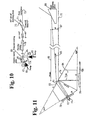
- FIG. 10 An optical solid-state amplifier pumped by diode lasers is shown in FIG. 10 .
- the light beam 72 to be amplified first strikes a polarization beam splitter 71 in a polarization with which the light beam 72 can pass the polarization beam splitter 71 without being reflected in another direction.
- the light beam 72 then passes a Faraday rotator 70 , in which the light beam 72 is rotated by 45 degrees in its polarization.
- the Faraday rotator 70 is achieved in that the electric field of the light beam 72 moves bonded to atoms of an irradiated by the light beam 72 medium charge carriers under the influence of an existing in the direction of propagation of the light beam 72 static magnetic field with the frequency of the light beam 72nd The movement of the charge carriers in turn generates a polarization generating a field, whereby according to Lorenz the static magnetic field creates a deflection component perpendicular to the driving electric light field. As a result, a polarization rotation is gradually generated as the light beam passes through the medium.
- the light beam 72 rotated by 45 degrees in its polarization then strikes a polarization-selective coating 69 of a neodymium-YAG crystal 68, and is deflected in the direction of a quarter-wave plate 67 located in the immediate vicinity of a surface of the neodymium-YAG crystal 68 .
- the quarter-wave plate 67 is arranged in such a way that the still linearly polarized light beam 72 is broken down into two mutually orthogonally polarized partial components, which have a phase difference of 90 ° when they pass through the quarter-wave plate 67 .
- a circularly polarized light wave is thus formed, which after complete reflection on a dielectric coating attached to the outside of the quarter-wave plate 67 passes the quarter-wave plate 67 in the opposite direction again, as a result of which the light beam 72 has a phase difference between the two orthogonally polarized components of the same size of 180 degrees arises, as a result of which the light beam 72 is composed again to form a linearly but orthogonally polarized light beam.
- This orthogonally polarized light beam 72 is reflected on the polarization-selective coating 69 and propagates to a surface 74 of the neodymium-YAG crystal 68 , on which it is completely reflected in the opposite direction. After a further reflection on the polarization-selective coating 69 , the orthogonally polarized light beam 72 passes through the quarter-wave plate 67 again , on the outer surface of which a complete reflection takes place.
- the light beam 72 which is now present in its original polarization, is not reflected by the polarization-selective coating 69 and passes through the Faraday rotator 70 in the opposite direction, is again rotated in its polarization by 45 degrees and is thereby reflected on the polarization beam splitter 71 in the direction of a beam 73 , In this way, the light beam 72 passes through the neodymium-YAG crystal 68 four times.
- the light beam 72 is optically amplified by the fact that the photons of the light beam 72 encounter optically excited atoms, which in turn are stimulated by the photons of the light beam 72 and release photons with the same wavelength upon transition into a non-excited state.
- the excited state of the corresponding atoms of the neodymium-YAG crystal 68 is produced by the photons of a light wave with a certain shorter wavelength, which are guided into the crystal in pump beams 65 and 66 .
- the dielectric coatings of the outer surface of the quarter-wave plate 67 and of the surface 74 are designed such that they do not reflect the beams 65 and 66, in contrast to the light beam 72 .
- the light beam 72 strikes a neodymium-YAG crystal 68 with a high density of excited atoms, with a weak light beam 72 a few photons will each generate many additional photons, that is to say they are amplified by a high factor. However, the absolute number of newly generated photons, measured by the high density of excited atoms in the neodymium-YAG crystal 68, is then low. Since the atoms spontaneously return to the non-excited state after a certain time, constant replacement must be ensured with a high output of pump light.
- a high power of the light beam 72 entering the neodymium-YAG crystal means that a large number of photons strikes excited atoms, but also drastically reduces the density of the excited atoms and thus the probability of the individual entering the neodymium-YAG crystal 68 entering photon of the light beam 72 to trigger a certain number of additional photons lowers. Now the vast majority of the excited atoms will no longer spontaneously, but stimulated by other photons, will change to the non-excited state and thus generate photons used for amplification.
- a light beam 75 to be amplified passes through a polarization-selective coating 76 into a neodymium-YAG crystal 84 in order to be reflected at a point 77 on the outside of a quarter-wave plate 78 after it has been baptized, the reflected polarity now being rotated by 90 degrees in its linear polarization
- Light beam 75 is reflected at the polarization-selective coating 76 at its original entry point into the neodymium-YAG crystal 84 in the direction of a mirror 79 attached in the immediate vicinity of the neodymium-YAG crystal.
- the mirror 79 is tilted by a small angle 80 relative to the right angle to the incident light beam 75, whereby the unchanged in its polarization at the mirror 79 reflected light beam 75 at point 81 to the polarization-selective coating 76 in the direction of the quarter-wave plate is reflected 78th
- the light beam 75 passes through the polarization selective coating 76 at a point 83 to propagate at an angle 85 with respect to the direction of the incoming light beam 75 .
- the coating 76 advantageously has an angle close to the value of the Brewster angle to the incoming light beam 75 and to the light beam emerging at point 83 .
- the partial reflection of the light beam emerging at point 83 into the neodymium-YAG crystal 84 must be minimized.
- the pump light is supplied in the same way as shown in Fig. 10 .
- the outside of the quarter-wave plate 78 and the reflective layer of the mirror 79 are also coated or designed in such a way that pump light is not reflected.
- light beam 75 thus traverses neodymium-YAG crystal 84 in 6 ways .
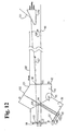
- FIG. 12 shows a further device with two-part neodymium-YAG crystal.
- a light beam 90 enters a neodymium-YAG crystal 93 at a point 91 to meet a polarization-selective layer 95 at point 94 , which allows the appropriately polarized light beam 90 to pass into an adjacent neodymium-YAG crystal 96 .
- the quarter-wave plate 98 After passing through a quarter-wave plate 98 and reflecting at a point 97 on the reflectively coated side of the quarter-wave plate 98 facing away from the neodymium-YAG crystal 96, the quarter-wave plate 98 is run through a second time in order to achieve a previous orthogonal polarization due to the mutual phase shift of 180 degrees between two orthogonal components to be obtained and thereby to be reflected at point 94 on the polarization-selective layer 95 in the direction of a second quarter-wave plate 100 .
- the light beam 90 By a small angle 101 of the quarter-wave plate 100 to the right angle of the light beam 90 coming in from point 94 , after a reflection in a point 99 twice passing through the quarter-wave plate 100, the light beam 90 , which is once again polarized, passes through the polarization-selective layer 95 onto one Point 102 of a reflective layer 101 .
- a further pump light source (not shown here for reasons of clarity) is generally connected to point 102 .
- the light beam 90 again crosses the polarization-selective layer 95 in the direction of the quarter-wave plate 100, on the side of which facing away from the neodymium-YAG crystal it is reflected in a point 103 laterally offset from point 99 , due to the two passes of the quarter-wave plate 100 with polarization rotated by 90 degrees to be reflected at the polarization-selective layer 95 at a point 104 in the direction of the quarter-wave plate 98 .
- the light beam 90 After reflection on the outside of the quarter-wave plate 98 in a point 105 laterally offset from point 97 , the light beam 90 passes through the polarization-selective layer 95 rotated by 90 degrees as a result of two passes through the quarter-wave plate 98, rotated 90 degrees again at a point laterally offset from point 91 106 to leave the neodymium-YAG crystal 93 .
- the light beam 90 now propagates in the opposite direction and additionally rotated by a small angle 107 over a distance 108 , after which it has reached a sufficient distance 109 from the entrance that allows its separation by a mirror 110 and an output beam 111 .
- Pump light is supplied through the two quarter-wave plates 98 and 100 , the sides thereof facing away from the neodymium-YAG crystal 96 not reflecting the pump light, but allowing it to pass, in contrast to the light beam 90 .
- the polarization-selective layer 95 also allows the pump light to pass independently of its polarization, as a result of which the neodymium-YAG crystal 93 also receives pump light. In this way, the neodymium-YAG crystal 93 is traversed in 4 ways, the neodymium-YAG crystal 96 even in 8 ways.
- the crystal 68 of an arrangement according to one of Claims 2 to 7 which can be used as a reinforcing medium, is preferably a neodymium-YAG crystal.
Landscapes
- Physics & Mathematics (AREA)
- Electromagnetism (AREA)
- Engineering & Computer Science (AREA)
- Plasma & Fusion (AREA)
- Optics & Photonics (AREA)
- Computer Networks & Wireless Communication (AREA)
- Signal Processing (AREA)
- Lasers (AREA)
- Optical Communication System (AREA)
Claims (10)
- Procédé servant à l'exploitation d'un système laser pour des communications optiques dans l'espace libre, notamment pour la production de lumière laser amplifiée dans les conditions de l'espace extra-atmosphérique, l'émission d'un laser solide non modulé à diodes ou pompé par des diodes (12) et émettant sur une fréquence optique étant soumise à une modulation (14), le faisceau collimaté (17) étant ensuite amené dans un amplificateur solide à pompage optique (18) au moyen d'une fibre optique (18A) vers une optique de modelage de faisceau (19),
caractérisé en ce que
l'émission est modulée en phase dans le modulateur électrooptique (14) afin de générer de la lumière laser modulée,
l'isolateur optique (16) guide la lumière laser modulée, sous forme d'un faisceau libre collimaté (17), dans l'amplificateur solide à pompage optique (18),
en ce que l'amplificateur solide (18) comprend un cristal (84), servant de milieu amplifiant, qui présente sur ses faces externes des couches à sélection de polarisation et réfléchissantes, et en ce qu'une lame quart d'onde (78) est prévue dans la zone d'une surface limite du cristal (84), de sorte que la lumière laser modulée effectue de multiples passages à travers le milieu productif de gain (84),
en ce qu'un miroir (79) est en outre placé près du cristal (84), sous un premier point de sortie de la lumière laser modulée (75), et est basculé d'un angle inférieur (80) à l'angle droit par rapport à un faisceau lumineux incident (75A), afin de permettre une séparation de la lumière laser modulée (75) entrante et sortante. - Dispositif destiné à générer de la lumière laser amplifiée pour des communications optiques dans l'espace libre, notamment dans les conditions de l'espace extra-atmosphérique, des moyens servant à générer de la lumière laser non modulée (12) étant reliés à des moyens servant à transmettre (13), en maintenant la polarisation (13), la lumière laser non modulée vers un modulateur électrooptique (14), et à des moyens servant à transmettre la lumière laser modulée (15) vers un isolateur optique (16),
caractérisé en ce que
le modulateur électrooptique (14) est un modulateur de phase,
l'isolateur optique (16) guide la lumière laser modulée sous forme d'un faisceau libre collimaté (17) dans l'amplificateur solide à pompage optique (18), auquel est relié, au moyen d'une fibre optique (18A), un autre isolateur optique (19) muni d'une optique de modelage de faisceau,
en ce que l'amplificateur solide (18) est pompé par des diodes laser,
en ce que l'amplificateur solide (18) comprend un cristal (84), servant de milieu amplifiant, qui est doté, sur ses faces externes, de couches à sélection de polarisation et réfléchissantes,
en ce qu'une lame quart d'onde (78) est prévue dans la zone d'une surface limite du cristal (84) et permet ainsi que la lumière laser modulée effectue de multiples passages à travers le milieu productif de gain (84), et
en ce qu'un miroir (79) est en outre placé près du cristal (84), sous un premier point de sortie de la lumière laser modulée (75), et est basculé d'un angle inférieur (80) à l'angle droit par rapport à un faisceau lumineux incident (75A), afin de permettre une séparation de la lumière laser modulée (75) entrante et sortante. - Dispositif conforme à la revendication 2,
caractérisé en ce que
le séparateur de faisceau à polarisation (32) est prévu en plusieurs exemplaires et qu'il est relié à au moins une lame demi-onde mobile (35) permettant qu'au moins les émissions de trois lasers à diodes polarisés (30) soient précisément orientées sur l'amplificateur solide (34). - Dispositif conforme à la revendication 2 ou 3,
caractérisé en ce que
l'amplificateur solide optique (18) pompé par des lasers à diodes (65,66) comprend un cristal (68) servant de milieu amplifiant, et
en ce que ce cristal (68) est muni, sur ses faces externes, d'un revêtement (69) à sélection de polarisation, de couches réfléchissantes (74) ainsi que d'une lame quart d'onde (67), et qu'il suscite ainsi les multiples passages de la lumière à amplifier à travers le milieu productif de gain (68). - Dispositif conforme à l'une des revendications 2 à 4,
caractérisé en ce que
un séparateur de faisceau à polarisation (24) est placé en aval des moyens servant à générer la lumière laser non modulée (12) à partir de deux émissions, polarisées de façon orthogonale, de deux sources de lumière de pompage (20, 21), au moyen duquel un faisceau unique (26) est amené conjointement à l'amplificateur solide (cristal de laser) à pompage optique (27). - Dispositif conforme à l'une des revendications 2 à 5,
caractérisé en ce qu'il est muni de lentilles réglables (22, 23, 31) destinées à orienter individuellement les émissions des sources de lumière de pompage (20, 21, 30). - Dispositif conforme à l'une des revendications 2 à 6,
caractérisé en ce que
l'amplificateur solide optique (18) pompé par des lasers à diodes (65, 66) comporte un dispositif servant (69, 70, 71) à plusieurs reprises d'isolateur optique (16, 19) et comprenant un rotateur de Faraday (70), le revêtement à sélection de polarisation (69) et un séparateur de faisceau à polarisation (71). - Dispositif conforme à l'une des revendications 4 à 7,
caractérisé en ce qu'un miroir réfléchissant (79) est en outre placé près du cristal (84) servant de milieu productif de gain, sous un premier point de sortie de la lumière laser à amplifier (75), et permet la séparation de la lumière laser à amplifier (75) entrante et sortante sans rotateur de Faraday supplémentaire ni séparateur de faisceau à polarisation, le miroir (79) étant basculé d'un angle faible (80) par rapport au faisceau lumineux incident. - Dispositif conforme à l'une des revendications 4 à 8,
caractérisé en ce que
le milieu productif de gain est réparti dans deux cristaux (93, 96) placés l'un contre l'autre, reliés l'un à l'autre sur une face par une couche à sélection de polarisation (95). - Dispositif conforme à l'une des revendications 4 à 9,
caractérisé en ce qu'il est réalisé un coudage du faisceau lumineux incident (90) par deux lames quart d'onde (98, 100), à travers le milieu productif de gain des deux cristaux (93, 96) placés l'un contre l'autre, vers le faisceau de sortie amplifié (111).
Applications Claiming Priority (3)
| Application Number | Priority Date | Filing Date | Title |
|---|---|---|---|
| CH314696 | 1996-12-20 | ||
| CH314696 | 1996-12-20 | ||
| CH3146/96 | 1996-12-20 |
Publications (2)
| Publication Number | Publication Date |
|---|---|
| EP0849894A1 EP0849894A1 (fr) | 1998-06-24 |
| EP0849894B1 true EP0849894B1 (fr) | 2003-05-21 |
Family
ID=4249612
Family Applications (1)
| Application Number | Title | Priority Date | Filing Date |
|---|---|---|---|
| EP97116148A Expired - Lifetime EP0849894B1 (fr) | 1996-12-20 | 1997-09-17 | Procédé et dispositif pour commander un système laser pour communication optique en espace libre |
Country Status (5)
| Country | Link |
|---|---|
| US (1) | US5974074A (fr) |
| EP (1) | EP0849894B1 (fr) |
| JP (1) | JPH10190119A (fr) |
| CA (1) | CA2222375A1 (fr) |
| DE (1) | DE59710120D1 (fr) |
Families Citing this family (13)
| Publication number | Priority date | Publication date | Assignee | Title |
|---|---|---|---|---|
| EP0863627B1 (fr) | 1997-03-07 | 2001-09-19 | Contraves Space AG | Procédé et dispositif pour le transport optique de données par satellites |
| DE59812374D1 (de) | 1998-03-03 | 2005-01-20 | Contraves Space Ag Zuerich | Quantenoptische Verstärker für optische Freiraum-Kommunikationssysteme |
| US6917581B2 (en) * | 2001-07-17 | 2005-07-12 | Ipr Licensing, Inc. | Use of orthogonal or near orthogonal codes in reverse link |
| US20040208602A1 (en) * | 2001-12-01 | 2004-10-21 | James Plante | Free space optical communications link tolerant of atmospheric interference |
| US20040109692A1 (en) * | 2002-12-09 | 2004-06-10 | James Plante | FSO communication systems having high performance detectors |
| US7277641B1 (en) | 2003-05-06 | 2007-10-02 | Ball Aerospace & Technologies Corp. | Multiple access space communications optical system using a common telescope aperture |
| US20050089333A1 (en) * | 2003-10-03 | 2005-04-28 | Near Margalit | Combining high-speed data and analog video on an optical fiber |
| US7668468B1 (en) | 2004-10-01 | 2010-02-23 | Ball Aerospace & Technologies Corp. | Numerous user laser communications optical system using chromatic waveplates and a common telescope aperture |
| CN100430813C (zh) * | 2004-11-12 | 2008-11-05 | 中国科学院光电技术研究所 | 高效激光倍频装置 |
| AU2009289425B2 (en) * | 2008-09-05 | 2013-10-24 | Ams Research Corporation | Laser system having switchable power modes |
| US8897326B2 (en) | 2008-09-08 | 2014-11-25 | Ams Research Corporation | Pump energy wavelength stabilization |
| WO2019005824A1 (fr) * | 2017-06-30 | 2019-01-03 | Imra America, Inc. | Peignes de fréquence de précision |
| EP3595196A1 (fr) * | 2018-07-12 | 2020-01-15 | Nederlandse Organisatie voor toegepast- natuurwetenschappelijk onderzoek TNO | Dispositif laser pour communication optique, système de communication optique et leur utilisation |
Family Cites Families (3)
| Publication number | Priority date | Publication date | Assignee | Title |
|---|---|---|---|---|
| JPH02139526A (ja) * | 1988-11-21 | 1990-05-29 | Fuji Photo Film Co Ltd | 光増幅装置 |
| US5249196A (en) * | 1992-05-21 | 1993-09-28 | The United States Of America As Represented By The Secretary Of The Navy | Internally folded scalable laser |
| JP3211448B2 (ja) * | 1993-01-27 | 2001-09-25 | ソニー株式会社 | レーザー光源装置 |
-
1997
- 1997-09-17 DE DE59710120T patent/DE59710120D1/de not_active Expired - Lifetime
- 1997-09-17 EP EP97116148A patent/EP0849894B1/fr not_active Expired - Lifetime
- 1997-12-17 CA CA002222375A patent/CA2222375A1/fr not_active Abandoned
- 1997-12-19 US US08/994,841 patent/US5974074A/en not_active Expired - Fee Related
- 1997-12-22 JP JP9352981A patent/JPH10190119A/ja active Pending
Also Published As
| Publication number | Publication date |
|---|---|
| EP0849894A1 (fr) | 1998-06-24 |
| US5974074A (en) | 1999-10-26 |
| CA2222375A1 (fr) | 1998-06-20 |
| JPH10190119A (ja) | 1998-07-21 |
| DE59710120D1 (de) | 2003-06-26 |
Similar Documents
| Publication | Publication Date | Title |
|---|---|---|
| EP0863628B1 (fr) | Méthode et dispositif pour l'opération d'un système d'émission à laser pour la communication optique dans l'espace libre | |
| DE69717600T2 (de) | Optische verstärker mit hoher spitzenleistung und hoher energie | |
| DE60108174T2 (de) | Leistungsskalierbare wellenleiterverstärker- und laserbauelemente | |
| DE69427673T2 (de) | Vorrichtung mit einem optischen Faserlaser oder Verstärker | |
| DE69034006T2 (de) | Optischer Verstärker, optisches Übertragungssystem mit einem optischen Verstärker und Verfahren zum Verstärken eines optischen Signals | |
| DE112004002187B4 (de) | Gepulste Laserquellen | |
| EP0849894B1 (fr) | Procédé et dispositif pour commander un système laser pour communication optique en espace libre | |
| EP0644633B1 (fr) | Laser à fibre optique à blocage de mode passif avec commutation non-linèaire de polarisation | |
| DE69203338T2 (de) | Vorrichtung und Verfahren für die Verstärkung und Verteilung eines kompensierten, SBS-freien optischen Strahls. | |
| EP0569353B1 (fr) | Structures guides d'ondes en niobate de lithium a dopage en terres rares | |
| DE69631817T2 (de) | Sender für modulierte und depolarisierte optische Signale | |
| EP0878880B1 (fr) | Dispositif pour opération dans l'espace des amplificateurs optiques à guide d'onde | |
| WO1986004999A1 (fr) | Matrice de resonateur integree pour separation selective de longueurs d'ondes ou jonction de canaux dans la plage de frequence de la technique des communications optiques | |
| DE3643569A1 (de) | Analysator fuer optische frequenzen | |
| IL105703A (en) | Device and method for increasing optical energy by using a two-beam coupling | |
| DE10006050B4 (de) | Direkt modulierbarer Laser | |
| DE60205745T2 (de) | Frequenzstabilisierte laserquelle | |
| EP0889563B1 (fr) | Amplificateur quantum optique pour systèmes de communication optique en espace libre | |
| DE10052461A1 (de) | Verfahren und Vorrichtung zum Erzeugen von Laserlicht | |
| DE68928761T2 (de) | Optische faser-breitbandlaser | |
| JPH02310982A (ja) | モード同期ファイバレーザ装置 | |
| Pribil et al. | 4 Laser Transmitters | |
| WO1998023000A1 (fr) | Systeme laser et amplificateur pour produire un faisceau laser dans la gamme d'ondes visibles | |
| DE4307721A1 (de) | Laserverstärker mit zweifacher optischer Weiche und Rückführung der Depolarisationsverluste | |
| DE4139859A1 (de) | Abstimmbarer zwei-wellenlaengen-laser fuer superheterodyn-interferometer |
Legal Events
| Date | Code | Title | Description |
|---|---|---|---|
| PUAI | Public reference made under article 153(3) epc to a published international application that has entered the european phase |
Free format text: ORIGINAL CODE: 0009012 |
|
| AK | Designated contracting states |
Kind code of ref document: A1 Designated state(s): BE CH DE FR GB IT LI SE |
|
| AX | Request for extension of the european patent |
Free format text: AL;LT;LV;RO;SI |
|
| 17P | Request for examination filed |
Effective date: 19980706 |
|
| AKX | Designation fees paid |
Free format text: BE CH DE FR GB IT LI SE |
|
| RBV | Designated contracting states (corrected) |
Designated state(s): BE CH DE FR GB IT LI SE |
|
| 17Q | First examination report despatched |
Effective date: 19991126 |
|
| RAP1 | Party data changed (applicant data changed or rights of an application transferred) |
Owner name: CONTRAVES SPACE AG |
|
| GRAH | Despatch of communication of intention to grant a patent |
Free format text: ORIGINAL CODE: EPIDOS IGRA |
|
| GRAH | Despatch of communication of intention to grant a patent |
Free format text: ORIGINAL CODE: EPIDOS IGRA |
|
| GRAA | (expected) grant |
Free format text: ORIGINAL CODE: 0009210 |
|
| AK | Designated contracting states |
Designated state(s): BE CH DE FR GB IT LI SE |
|
| PG25 | Lapsed in a contracting state [announced via postgrant information from national office to epo] |
Ref country code: IT Free format text: LAPSE BECAUSE OF FAILURE TO SUBMIT A TRANSLATION OF THE DESCRIPTION OR TO PAY THE FEE WITHIN THE PRESCRIBED TIME-LIMIT;WARNING: LAPSES OF ITALIAN PATENTS WITH EFFECTIVE DATE BEFORE 2007 MAY HAVE OCCURRED AT ANY TIME BEFORE 2007. THE CORRECT EFFECTIVE DATE MAY BE DIFFERENT FROM THE ONE RECORDED. Effective date: 20030521 Ref country code: GB Free format text: LAPSE BECAUSE OF FAILURE TO SUBMIT A TRANSLATION OF THE DESCRIPTION OR TO PAY THE FEE WITHIN THE PRESCRIBED TIME-LIMIT Effective date: 20030521 |
|
| REG | Reference to a national code |
Ref country code: GB Ref legal event code: FG4D Free format text: NOT ENGLISH |
|
| REG | Reference to a national code |
Ref country code: CH Ref legal event code: EP |
|
| REF | Corresponds to: |
Ref document number: 59710120 Country of ref document: DE Date of ref document: 20030626 Kind code of ref document: P |
|
| REG | Reference to a national code |
Ref country code: CH Ref legal event code: NV Representative=s name: OK PAT AG PATENTE MARKEN LIZENZEN |
|
| PG25 | Lapsed in a contracting state [announced via postgrant information from national office to epo] |
Ref country code: SE Free format text: LAPSE BECAUSE OF FAILURE TO SUBMIT A TRANSLATION OF THE DESCRIPTION OR TO PAY THE FEE WITHIN THE PRESCRIBED TIME-LIMIT Effective date: 20030821 |
|
| PG25 | Lapsed in a contracting state [announced via postgrant information from national office to epo] |
Ref country code: BE Free format text: LAPSE BECAUSE OF NON-PAYMENT OF DUE FEES Effective date: 20030930 |
|
| GBV | Gb: ep patent (uk) treated as always having been void in accordance with gb section 77(7)/1977 [no translation filed] |
Effective date: 20030521 |
|
| ET | Fr: translation filed | ||
| PLBE | No opposition filed within time limit |
Free format text: ORIGINAL CODE: 0009261 |
|
| STAA | Information on the status of an ep patent application or granted ep patent |
Free format text: STATUS: NO OPPOSITION FILED WITHIN TIME LIMIT |
|
| BERE | Be: lapsed |
Owner name: *CONTRAVES SPACE A.G. Effective date: 20030930 |
|
| 26N | No opposition filed |
Effective date: 20040224 |
|
| PG25 | Lapsed in a contracting state [announced via postgrant information from national office to epo] |
Ref country code: FR Free format text: LAPSE BECAUSE OF NON-PAYMENT OF DUE FEES Effective date: 20040730 |
|
| REG | Reference to a national code |
Ref country code: FR Ref legal event code: ST |
|
| REG | Reference to a national code |
Ref country code: CH Ref legal event code: PFA Owner name: OERLIKON SPACE AG Free format text: CONTRAVES SPACE AG#SCHAFFHAUSERSTRASSE 580#8052 ZUERICH (CH) -TRANSFER TO- OERLIKON SPACE AG#SCHAFFHAUSERSTRASSE 580#8052 ZUERICH (CH) |
|
| PG25 | Lapsed in a contracting state [announced via postgrant information from national office to epo] |
Ref country code: FR Free format text: LAPSE BECAUSE OF NON-PAYMENT OF DUE FEES Effective date: 20030930 |
|
| PGFP | Annual fee paid to national office [announced via postgrant information from national office to epo] |
Ref country code: CH Payment date: 20100914 Year of fee payment: 14 |
|
| PGFP | Annual fee paid to national office [announced via postgrant information from national office to epo] |
Ref country code: DE Payment date: 20100915 Year of fee payment: 14 |
|
| REG | Reference to a national code |
Ref country code: CH Ref legal event code: PL |
|
| REG | Reference to a national code |
Ref country code: DE Ref legal event code: R119 Ref document number: 59710120 Country of ref document: DE Effective date: 20120403 |
|
| PG25 | Lapsed in a contracting state [announced via postgrant information from national office to epo] |
Ref country code: LI Free format text: LAPSE BECAUSE OF NON-PAYMENT OF DUE FEES Effective date: 20110930 Ref country code: CH Free format text: LAPSE BECAUSE OF NON-PAYMENT OF DUE FEES Effective date: 20110930 Ref country code: DE Free format text: LAPSE BECAUSE OF NON-PAYMENT OF DUE FEES Effective date: 20120403 |