EP0878880B1 - Dispositif pour opération dans l'espace des amplificateurs optiques à guide d'onde - Google Patents
Dispositif pour opération dans l'espace des amplificateurs optiques à guide d'onde Download PDFInfo
- Publication number
- EP0878880B1 EP0878880B1 EP98105826A EP98105826A EP0878880B1 EP 0878880 B1 EP0878880 B1 EP 0878880B1 EP 98105826 A EP98105826 A EP 98105826A EP 98105826 A EP98105826 A EP 98105826A EP 0878880 B1 EP0878880 B1 EP 0878880B1
- Authority
- EP
- European Patent Office
- Prior art keywords
- optical waveguide
- light
- optical
- amplified
- amplifier
- Prior art date
- Legal status (The legal status is an assumption and is not a legal conclusion. Google has not performed a legal analysis and makes no representation as to the accuracy of the status listed.)
- Expired - Lifetime
Links
Images



Classifications
-
- H—ELECTRICITY
- H04—ELECTRIC COMMUNICATION TECHNIQUE
- H04B—TRANSMISSION
- H04B10/00—Transmission systems employing electromagnetic waves other than radio-waves, e.g. infrared, visible or ultraviolet light, or employing corpuscular radiation, e.g. quantum communication
- H04B10/11—Arrangements specific to free-space transmission, i.e. transmission through air or vacuum
- H04B10/118—Arrangements specific to free-space transmission, i.e. transmission through air or vacuum specially adapted for satellite communication
-
- H—ELECTRICITY
- H01—ELECTRIC ELEMENTS
- H01S—DEVICES USING THE PROCESS OF LIGHT AMPLIFICATION BY STIMULATED EMISSION OF RADIATION [LASER] TO AMPLIFY OR GENERATE LIGHT; DEVICES USING STIMULATED EMISSION OF ELECTROMAGNETIC RADIATION IN WAVE RANGES OTHER THAN OPTICAL
- H01S3/00—Lasers, i.e. devices using stimulated emission of electromagnetic radiation in the infrared, visible or ultraviolet wave range
- H01S3/05—Construction or shape of optical resonators; Accommodation of active medium therein; Shape of active medium
- H01S3/06—Construction or shape of active medium
- H01S3/063—Waveguide lasers, i.e. whereby the dimensions of the waveguide are of the order of the light wavelength
- H01S3/067—Fibre lasers
- H01S3/06704—Housings; Packages
-
- H—ELECTRICITY
- H01—ELECTRIC ELEMENTS
- H01S—DEVICES USING THE PROCESS OF LIGHT AMPLIFICATION BY STIMULATED EMISSION OF RADIATION [LASER] TO AMPLIFY OR GENERATE LIGHT; DEVICES USING STIMULATED EMISSION OF ELECTROMAGNETIC RADIATION IN WAVE RANGES OTHER THAN OPTICAL
- H01S3/00—Lasers, i.e. devices using stimulated emission of electromagnetic radiation in the infrared, visible or ultraviolet wave range
- H01S3/05—Construction or shape of optical resonators; Accommodation of active medium therein; Shape of active medium
- H01S3/06—Construction or shape of active medium
- H01S3/063—Waveguide lasers, i.e. whereby the dimensions of the waveguide are of the order of the light wavelength
- H01S3/067—Fibre lasers
- H01S3/06754—Fibre amplifiers
-
- H—ELECTRICITY
- H01—ELECTRIC ELEMENTS
- H01S—DEVICES USING THE PROCESS OF LIGHT AMPLIFICATION BY STIMULATED EMISSION OF RADIATION [LASER] TO AMPLIFY OR GENERATE LIGHT; DEVICES USING STIMULATED EMISSION OF ELECTROMAGNETIC RADIATION IN WAVE RANGES OTHER THAN OPTICAL
- H01S3/00—Lasers, i.e. devices using stimulated emission of electromagnetic radiation in the infrared, visible or ultraviolet wave range
- H01S3/05—Construction or shape of optical resonators; Accommodation of active medium therein; Shape of active medium
- H01S3/06—Construction or shape of active medium
- H01S3/063—Waveguide lasers, i.e. whereby the dimensions of the waveguide are of the order of the light wavelength
- H01S3/067—Fibre lasers
- H01S3/06754—Fibre amplifiers
- H01S3/06787—Bidirectional amplifier
-
- H—ELECTRICITY
- H01—ELECTRIC ELEMENTS
- H01S—DEVICES USING THE PROCESS OF LIGHT AMPLIFICATION BY STIMULATED EMISSION OF RADIATION [LASER] TO AMPLIFY OR GENERATE LIGHT; DEVICES USING STIMULATED EMISSION OF ELECTROMAGNETIC RADIATION IN WAVE RANGES OTHER THAN OPTICAL
- H01S3/00—Lasers, i.e. devices using stimulated emission of electromagnetic radiation in the infrared, visible or ultraviolet wave range
- H01S3/09—Processes or apparatus for excitation, e.g. pumping
- H01S3/091—Processes or apparatus for excitation, e.g. pumping using optical pumping
- H01S3/094—Processes or apparatus for excitation, e.g. pumping using optical pumping by coherent light
- H01S3/094003—Processes or apparatus for excitation, e.g. pumping using optical pumping by coherent light the pumped medium being a fibre
-
- H—ELECTRICITY
- H01—ELECTRIC ELEMENTS
- H01S—DEVICES USING THE PROCESS OF LIGHT AMPLIFICATION BY STIMULATED EMISSION OF RADIATION [LASER] TO AMPLIFY OR GENERATE LIGHT; DEVICES USING STIMULATED EMISSION OF ELECTROMAGNETIC RADIATION IN WAVE RANGES OTHER THAN OPTICAL
- H01S5/00—Semiconductor lasers
- H01S5/40—Arrangement of two or more semiconductor lasers, not provided for in groups H01S5/02 - H01S5/30
- H01S5/4018—Lasers electrically in series
Definitions
- the present invention relates to an arrangement of a quantum optical amplifiers designed as optical fibers taking into account the special conditions encountered in space.
- satellites for communication and navigation purposes are mainly characterized by the use of single or fewer satellites, which via microwave radio channels only with the earthbound operator or user Connect.
- larger groups of satellites will be used for one and the same purpose can be put into orbit as, for example, partially Communication systems in the implementation phase based on in low altitude orbiting satellite. Their limited visibility requires the permanent handover of an earthbound user between a multitude continuously passing satellites.
- diode-pumped solid-state lasers advantageous if particularly energy-efficient coherent transmission methods are used come.
- the required external modulation of the phase of the laser emitted light must be in the form of an optical at high modulation bandwidth Waveguide designed modulator can be made, which is not high optical performance can be operated.
- the transition from one to a collimated Solid-state beam-emitting lasers in a waveguide structure are considered critical and lossy, which creates an additional power reserve in the subsequent quantum optical Amplifier is necessary. Its design as a solid-state amplifier includes others technical problems.
- patents US-A-5,459,328 and JP-A-63 256 905 describe various ones Details related to optical elements.
- U.S. Patent A-5,459,328 relates a driver circuit equipped with light-emitting diodes connected in series, in which the cathode of a photodiode with the inverting input of an operational amplifier and the Japanese patent relates to an apparatus for Rotation of the polarization of a fiber about its axis by mechanical means, in particular with the help of plates and screws.
- neodymium-YAG solid-state lasers used a four-level system arises that the absorption of signal light in poorly pumped optically Areas of the reinforcing medium prevented.
- the optically amplifying optical waveguide is attached to the wall by means of elastic bands attached with nitrogen-filled housing, which optionally also essential electronic Components such as B. laser diodes for optically pumping the amplifier can include.
- the nitrogen filling is used to create earth-like operating conditions. So can, if the lack of convection permits, locally generated heat is dissipated and outgassing of components in a vacuum can be prevented. Harmful outgassing are bound using appropriate agents.
- Optical power can be radiated into and out of the housing in the form of collimated beams through quartz glass windows consisting of plane-parallel plates; alternatively, this is also possible via gas-tight fiber optic cables through the housing wall.
- quartz glass windows consisting of plane-parallel plates; alternatively, this is also possible via gas-tight fiber optic cables through the housing wall.
- plane-parallel plates are provided as windows, which are replaced by an optical lens in particularly light versions, depending on the embodiment, the radiation at Brewster angle is provided to eliminate reflections in the polarization direction used. Irrespective of the operating state of the entire optical transmission device, pump light and the spontaneously emitted light resulting from the absorption of the pump light on the wavelength of the signal light or amplified signal light continuously flow through the amplifying optical waveguide used.
- Color centers generally significantly increase the optical attenuation of optical fibers.
- the polarization of the light leaving the optical amplifier is determined by means of Coils generated electronically controlled magnetic field acting along the fiber direction.
- the reinforcing optical waveguide is provided in a particularly compact construction to be used in both directions of propagation, with the signal light to be amplified at one end of the optical fiber one of its polarization there by 90 degrees is reflected rotated and returns orthogonally polarized (single polarization fiber amplifier, I.N. Duling, R.D. Esman, El. Lett., 1992, p. 1126). Entrance and exit of the Amplifiers are at the other end of the optical fiber through a polarization beam splitter Cut.
- optical fibers All-fiber faraday rotator made by a multiturn figure of eight coil with matched birefringence V. Annovazzi-Lodi et al., IEEE JLT, 1995, p. 2349
- a special version of this optical waveguide is the quantum optical one Integrated amplifier.
- the cross section of the optical waveguide itself consists of several layers, one core layer only one electrodynamic mode of the signal light leads, while another layer together with a cladding layer one multimodal waveguide, in which the pump light is coupled with high efficiency can be.
- the coupling occurs via collimated beams of individual laser diodes, overlapping using both orthogonal directions of polarization, but otherwise not overlapping in close proximity to each other in the multi-mode waveguide be performed, whereby disturbing overlay effects are largely avoided.
- the advantageous, efficient use of the pump light is due to the perfect overlap the same with the light to be amplified over the very long distance of the optical waveguide guaranteed.
- the high utilization of the pump light is also due to the high intensity of the light to be amplified in the waveguide and thus a high rate stimulated Guaranteed emissions.
- Faraday rotator are also nor the stability of the polarization and the double use of the To call the optical fiber by about half the shorter length of the same.
- the inversion of both orthogonal polarization directions is used, which in addition to one further increase in efficiency a relatively low level of disruptive spontaneous Emission causes.
- FIG. 1 of an amplifier housing 2 filled with nitrogen has a recess in which a plane-parallel quartz glass plate 4 is inserted, through which light rays can enter and exit the housing.
- the amplifier housing 2 rests on heat-insulating supports 3a , 3b and is temperature-stabilized by a Peltier element 5 , the side of which is not connected to the amplifier housing 2 is connected to a heat-conductive band 1 with a heat or cold sink by means of a thermally conductive band.
- the amplifier housing 2 is filled with nitrogen or a gas with comparable favorable properties in order to achieve earth-like operating conditions. Reference should be made to heat dissipation and outgassing from various materials in a vacuum.
- a parallel operation of an amplifier located in a vacuum is conceivable as a long-term experiment, but the arrangement described has the advantage of greater safety in view of the fact that experience with the long-term operation of fiber-optic elements in space is not yet abundant.
- the gas can be filled below half the pressure found on the ground.
- a filling under ambient pressure is also provided, which is blown off to a predetermined pressure during the ascent phase of a satellite via a pressure relief valve 15 .
- the second exemplary embodiment of the open amplifier housing 2 shown in FIG. 2a illustrates the functioning of the arrangement by means of the components stored in it.
- a collimated light beam 9a from a solid-state laser serving as a light source - not shown for the sake of clarity - passes undeflected a polarization beam splitter 7 in order to be coupled via a further propagation path 6 through the quartz glass plate 4 and a first lens 10 into an optical waveguide 12 , which is connected by an elastic one Band 14 is fixed to the case back.
- the optical waveguide 12 contains the reinforcing medium, which is optically pumped through another end of the optical waveguide by means of a pump light beam 18 .
- the pumping light beam 18 is coupled in via a second lens 19 through a layer 17 at the end of the optical waveguide 12 which is drawn through a device 16 and which has a reflecting effect for the amplified light coming from the solid-state laser, but not a reflecting effect for the pumping light.
- the device 16 causes the polarization to rotate by 90 degrees, which is reproduced on the input of the optical waveguide 12 located at the lens 10 , which is why the amplified light deflects the amplifier via the propagation path 6 and the polarization beam splitter 7 Beam 11a leaves.
- An angle 8 of the propagation path 6 to the surface of the quartz glass plate 4 can assume the value of the Brewster angle for the incoming beam 9a in order to avoid reflections.
- the polarization beam splitter 7 can also be designed in the form of a polarization-selective fiber-optic coupler attached to the optical waveguide 12 , which enables the direct attachment of a phase modulator designed in waveguide form.
- Fig. 2b Such a modification can be seen in Fig. 2b .
- the coupler 13 essentially consists of two closely birefringent and consequently polarization-maintaining optical waveguides, in which light guided in a specific polarization direction is coupled into the respectively adjacent optical waveguide, but is omitted in the orthogonal polarization direction.
- the optical waveguide 12 can also be operated in a vacuum under thermally controllable homogeneous conditions.
- the optical waveguide 12 which is spun into a braid-like network of threads consisting of very thin and thermally conductive material, is wound onto a thermally conductive body 104 and fixed with a band-like body 106 which is shaped to match the body 104 .
- the temperature of the body 104 can be regulated by appropriate means.
- An additional possibility is to wind the light waveguide 12 , which is provided with a thin protective layer and is wound on a rounded body, with several layers of thin Telflon tape, which adheres to one another without adhesive due to its cohesion.
- the device 16 for rotating the polarization of the light to be amplified is shown in FIG. 3 and essentially consists of a number of eight-shaped windings of the optical waveguide 12 , which in the orientation shown are located in a permanent magnetic field 24 present between poles 22 of a permanent magnet .
- a continuous Farady rotation takes place, which is 45 degrees per pass and adds up to 90 degrees in the case of reflected light.
- An additional electromagnet 23 is used for subsequent adjustment of the device during the mission by changing the magnetic field 24 .
- FIG. 4 shows in cross section zones of different refractive index of the optical waveguide 12 used in the arrangement according to FIG. 2a , which has the highest optical refractive index within a circular zone 26 .
- This is enclosed by a further zone 28 , the refractive index of which is only insignificantly lower, so that, despite their relatively high expansion, both zones 26 and 28 only lead an electrodynamic mode of the light to be amplified.
- a zone 30 enclosing both zones 28 and 26 has a significantly lower optical refractive index, so that together with zones 26 and 28 a multimode optical waveguide is formed, in which the pump light is guided. This therefore flows through the zone 26 containing the profit-generating medium, which guides the light to be amplified.
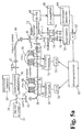
- FIG. 5a shows, on the basis of an experimental setup, a further principle for controlling the polarization of a light wave propagating in an optical waveguide 38 , which is generated by a laser 32 .
- the light emitted by the laser 32 is broken down into two partial beams by means of a partially transparent mirror 34 , a part of this light beam being passed through an acousto-optical modulator 40 , the optical frequency of which is shifted by the frequency of the oscillator 54 .
- a second part of the light beam is coupled into an optical waveguide 38 , which winds in two coils 48 and 50 , which are surrounded by electrical coils 52 .
- the direct voltage generated by the latter is fed into an analog-digital converter, the measured values of which feed a microprocessor 60 . Its output data influence the setpoints of current sources 56 feeding the electrical coils 52 via digital-analog converters 58 and thus the polarization of the light wave leaving the optical waveguide 38 via the resulting extent of the Faraday rotation.
- a method of manipulating the polarization of one that is orthogonal to each other in both Modes of an optical fiber propagating light wave is the rotation of two as Replacement for the collimated light beams that are used in free space Finding quarter-wave plates used optical fiber loops. This will be the stronger birefringence of the optical waveguide resulting from the winding of the optical waveguide exploited the light waves in both mutually orthogonal modes in their Shift phase to each other by 90 degrees.
- pressure can also be applied to the side of the rotating loop.
- 5b shows a device suitable for this.
- An optical waveguide 118 resting on a base plate 108 and wound around a cylinder 112 mounted thereon by means of a threaded screw 110 is subjected to mechanical pressure by means of a further cylindrical body 116 which results from the cylinder screw 114 used to fasten the body 116 and the body 116 located tensioned coil spring 120 derives.
- the mechanical pressure can also be generated by means of electromechanical means.
- a body 112 made of piezoelectric material is provided, which changes in its extension when an electrical voltage is applied in the direction of the threaded screw 114 .
- Fig. 6 shows a block diagram of a power supply and optical power control unit for the pumping light power-generating laser diodes of the quantum optical amplifier.
- the laser diodes are integrated in circuit blocks 84 through which a current generated in a source 82 flows. Since the required current strength is quite high, but the operating voltage of the blocks is relatively low, the series connection of all operated or redundant circuit blocks 84 has proven to be the most energy-efficient method in adaptation to the satellite on-board voltage. This applies to both the waste heat generated and the electrical energy consumption to be minimized.
- control unit 80 which measures the light power generated by all the laser diodes by means of a photodiode 88 and receives data about the light powers of the individual laser diodes via photodiodes attached in the individual circuit blocks 84 directly to the individual laser diodes . It is furthermore provided to replace the laser diode in one or more of said circuit blocks with the connections of coils provided for polarization control, one or more photodiodes together with polarization filters providing the corresponding actual value.
- FIG. 7 shows the circuit block 84 in the form of a controller, ie that in this case no information about the operating state of a laser diode 98 flows into the control unit 80 .
- the setpoint value of the photocurrent generated by the laser diode 98 is applied in the form of an electrical voltage to the non-inverting input 92 of an operational amplifier 90 , an inverting input 94 of this operational amplifier being the actual value of the photocurrent generated in a suitably connected photodiode 102 in the form of an electrical voltage receives.
- the comparison of the actual and setpoint values leads to an output voltage of the operational amplifier 90 , which leads, by means of a correspondingly connected transistor 100, into a short-circuit current bridging the connections of the laser diode 98 which is proportional thereto.
- a short circuit in the laser diode 98 only causes the current flowing through the transistor to be stepped up, while a failure of the conductivity of the laser diode 98 also leads to an upward regulation of the current flowing through the transistor 100 due to the lack of photocurrent.
- a total failure of these two current paths is intercepted by the series connection of semiconductor diodes 96 in parallel.
Landscapes
- Physics & Mathematics (AREA)
- Electromagnetism (AREA)
- Engineering & Computer Science (AREA)
- Plasma & Fusion (AREA)
- Optics & Photonics (AREA)
- Microelectronics & Electronic Packaging (AREA)
- Astronomy & Astrophysics (AREA)
- General Physics & Mathematics (AREA)
- Computer Networks & Wireless Communication (AREA)
- Signal Processing (AREA)
- Lasers (AREA)
- Optical Modulation, Optical Deflection, Nonlinear Optics, Optical Demodulation, Optical Logic Elements (AREA)
Claims (10)
- Structure d'un amplificateur à optique quantique pouvant fonctionner dans l'espace et conçu comme un guide d'ondes, telle quele guide d'ondes utilisé (12) est alimenté en permanence par un flux lumineux au moins suffisant pour que les centres colorés apparaissant par suite du rayonnement de freinage soient blanchis,le guide d'ondes (12) est parcouru dans les deux sens par la lumière à amplifier,une extrémité du guide d'ondes lumineuses est recouverte d'une couche (17) qui agit de façon réfléchissante pour la lumière à amplifier et qui, en revanche, laisse passer la lumière de pompage (18) sans réflexion,la réflexion de la lumière à amplifier s'accompagne d'une rotation de la polarisation à 90 degrés, elle-même réalisée par une rotation de Faraday,le rotateur de Faraday nécessaire est fabriqué en incurvant le guide d'ondes lumineuses (12) ou en amenant une partie de ce dernier dans un champ magnétique,la séparation de la lumière à amplifier entrant dans l'amplificateur et en sortant (9a, 11a ; 9b, 11b) se fait à l'aide d'un séparateur de faisceau de polarisation (7) ou de moyens appropriés du même type, ou bien à l'aide d'un coupleur à fibre optique à sélection de polarisation (13), etdes moyens d'ajustement et de contrôle de la double réfraction sont prévus, ce qui comprend un support (108) sur lequel est appuyé un guide d'ondes (118) enroulé autour d'un premier cylindre (112), sur lequel est exercée une pression mécanique au moyen d'un autre élément cylindrique (116) enveloppant le premier cylindre, le guide d'ondes (118) étant au moins enroulé une fois sur le premier cylindre (112).
- Structure d'un amplificateur à optique quantique pouvant fonctionner dans l'espace et conçu comme un guide d'ondes, telle quele guide d'ondes utilisé (12) est alimenté en permanence par un flux lumineux au moins suffisant pour que les centres colorés apparaissant par suite du rayonnement de freinage soient blanchis,le guide d'ondes (12) est parcouru dans les deux sens par la lumière à amplifier,une extrémité du guide d'ondes lumineuses est recouverte d'une couche (17) qui agit de façon réfléchissante pour la lumière à amplifier et qui, en revanche, laisse passer la lumière de pompage (18) sans réflexion,la réflexion de la lumière à amplifier s'accompagne d'une rotation de la polarisation à 90 degrés, elle-même réalisée par une rotation de Faraday,le rotateur de Faraday nécessaire est fabriqué en incurvant le guide d'ondes lumineuses (12) ou en amenant une partie de ce dernier dans un champ magnétique,la séparation de la lumière à amplifier entrant dans l'amplificateur et en sortant (9a, 11a ; 9b, 11b) se fait à l'aide d'un séparateur de faisceau de polarisation (7) ou de moyens appropriés du même type, ou bien à l'aide d'un coupleur à fibre optique à sélection de polarisation (13), etles diodes lasers de l'amplificateur à optique quantique qui produisent la lumière de pompage sont intégrées dans des blocs de connexion (84) montés en série avec une source de courant constante (82), une partie du courant parcourant chaque bloc de connexion (84) étant déviée dans ce dernier autour de la diode laser, afin de réguler le flux de courant passant dans les différentes diodes lasers, de telle sorte que la régulation du courant circulant effectivement à travers les différentes diodes lasers se fait par une unité de contrôle (80) et une photodiode (88) qui lui est reliée, mesurant le flux lumineux produit par toutes les diodes lasers.
- Structure selon la revendication 2, caractérisée en ce que sont prévus des moyens de contrôle de la polarisation d'une onde lumineuse se propageant dans un guide d'ondes lumineuses (38), de telle façon que la lumière est décomposée en deux faisceaux partiels, une partie de ce faisceau lumineux étant guidée à travers un modulateur (40), dont la fréquence optique est décalée de la fréquence d'un oscillateur (54), et une deuxième partie du faisceau lumineux étant couplée dans le guide d'ondes lumineuses (38), qui est incurvé et entouré de bobines électriques (52) alimentées par des sources de courant (56), ceci créant dans le guide d'ondes (38), dans la direction de propagation de l'onde lumineuse couplée, un champ magnétique, entraínant à son tour une rotation de Faraday, tandis que s'établit ensuite, après découplage hors du guide d'ondes (38), une jonction du faisceau lumineux ainsi créé avec le premier faisceau partiel à fréquence décalée, et que les deux faisceaux partiels sont détectés, dans un photodétecteur (68), comme superposés l'un à l'autre, et que, après passage d'un détecteur d'enveloppe (64), la tension continue produite par celui-ci est amenée dans un convertisseur analogique-numérique (62), dont les données de mesure alimentent un microprocesseur (60), les données de sortie de ce dernier influant sur les valeurs prescrites des sources de courant (56) alimentant les bobines électriques (52) et, par conséquent, sur la polarisation de l'onde lumineuse quittant le guide d'ondes (38), par suite de la dimension de la rotation de Faraday qui en résulte.
- Structure selon la revendication 3, caractérisée en ce que le modulateur (40) est un modulateur acousto-optique raccordé à un oscillateur (54).
- Structure selon l'une des revendications 2 à 4, caractérisée en ce que, afin d'éviter que des informations concernant l'état de fonctionnement d'une diode laser (98) soient obligées de passer dans l'unité de contrôle (80), chaque bloc de contrôle (84) est conçu sous forme d'un régulateur, la valeur prescrite du courant photoélectrique produit par une diode laser (98) étant donnée sur une entrée non inversée (92) d'un amplificateur opérationnel (90) sous forme d'une tension électrique, tandis qu'une entrée inversée (94) de cet amplificateur opérationnel reçoit, sous forme d'une tension électrique, la valeur effective du courant photoélectrique produit dans une photodiode (102) disposée de façon appropriée, de telle sorte que l'équilibrage de la valeur effective et de la valeur prescrite conduit à une tension de sortie de l'amplificateur opérationnel (90), qui, à l'aide d'un transistor (100) disposé de façon adéquate, amène à un courant de court-circuit qui lui est proportionnel, court-circuitant les connexions de la diode laser (98).
- Structure selon l'une des revendications 3 à 5, caractérisée en ce queles sources de courant (56) sont reliées au microprocesseur (60) par un convertisseur analogique-numérique (58).
- Structure selon l'une des revendications 1 à 6, caractérisée en ce quele guide d'ondes lumineuses (12) est entouré d'un mince entrelacement en forme de torons et est enroulé sur un élément thermoconductible (104).
- Structure selon l'une des revendications 1 à 7, caractérisée en ce quele guide d'ondes lumineuses (12) est enveloppé par une mince couche de protection, de préférence en Téflon, et est conçu comme une bobine multicouches.
- Structure selon l'une des revendications 1 à 8, caractérisée en ce quele guide d'ondes lumineuses (12, 38, 118) est logé dans un boítier fermé (2) étanche au gaz, rempli d'un gaz qui est de préférence de l'azote.
- Structure selon la revendication 9, caractérisée en ce que le guide d'ondes lumineuses (12, 38, 118) est logé dans un boítier fermé (2) étanche au gaz, dont le contenu gazeux présente une pression équivalente à la moitié de la pression atmosphérique terrestre.
Applications Claiming Priority (3)
| Application Number | Priority Date | Filing Date | Title |
|---|---|---|---|
| CH154097 | 1997-06-25 | ||
| CH154097 | 1997-06-25 | ||
| CH1540/97 | 1997-06-25 |
Publications (2)
| Publication Number | Publication Date |
|---|---|
| EP0878880A1 EP0878880A1 (fr) | 1998-11-18 |
| EP0878880B1 true EP0878880B1 (fr) | 2000-12-13 |
Family
ID=4212810
Family Applications (1)
| Application Number | Title | Priority Date | Filing Date |
|---|---|---|---|
| EP98105826A Expired - Lifetime EP0878880B1 (fr) | 1997-06-25 | 1998-03-31 | Dispositif pour opération dans l'espace des amplificateurs optiques à guide d'onde |
Country Status (5)
| Country | Link |
|---|---|
| US (1) | US6018602A (fr) |
| EP (1) | EP0878880B1 (fr) |
| JP (1) | JPH1126852A (fr) |
| CA (1) | CA2234854A1 (fr) |
| DE (1) | DE59800382D1 (fr) |
Families Citing this family (20)
| Publication number | Priority date | Publication date | Assignee | Title |
|---|---|---|---|---|
| ATE262229T1 (de) * | 1998-12-15 | 2004-04-15 | Contraves Space Ag | Leistungsverstärker zum verstärken einer laserstrahlung, verfahren zur herstellung und verwendung des leistungsverstärkers |
| WO2000046889A1 (fr) * | 1999-02-05 | 2000-08-10 | Sumitomo Electric Industries, Ltd. | Amplificateur a fibre |
| DE10036283A1 (de) * | 2000-07-26 | 2002-02-07 | Bosch Gmbh Robert | Laserdiodenanordnung |
| US6788870B1 (en) | 2001-11-08 | 2004-09-07 | Tyco Telecommunications (Us) Inc. | Isothermal fiber optic tray |
| DE10209374A1 (de) * | 2002-03-02 | 2003-07-31 | Rofin Sinar Laser Gmbh | Diodenlaseranordnung mit einer Mehrzahl von elektrisch in Reihe geschalteten Diodenlasern |
| US6728275B2 (en) * | 2002-09-19 | 2004-04-27 | Trw Inc. | Fault tolerant laser diode package |
| JP2006512780A (ja) * | 2002-12-27 | 2006-04-13 | オスラム オプト セミコンダクターズ ゲゼルシャフト ミット ベシュレンクテル ハフツング | レーザダイオード構成素子、及び、相互に直列接続された多数のレーザダイオードインゴットを有する電子回路装置 |
| DE10306312A1 (de) * | 2002-12-27 | 2004-07-22 | Osram Opto Semiconductors Gmbh | Laserdiodenbauelement und elektronische Schaltungsanordnung mit einer Mehrzahl von seriell zueinander verschalteten Laserdiodenbarren |
| JP2004253525A (ja) * | 2003-02-19 | 2004-09-09 | Nec Corp | 半導体レーザ装置及び半導体レーザ励起固体レーザ装置 |
| DE10328440A1 (de) * | 2003-06-20 | 2005-01-13 | Jenoptik Laserdiode Gmbh | Anordnung von mehreren Hochleistungsdiodenlasern |
| JP5412739B2 (ja) | 2008-03-26 | 2014-02-12 | 富士通株式会社 | 光増幅装置 |
| US8345720B2 (en) * | 2009-07-28 | 2013-01-01 | Northrop Grumman Systems Corp. | Laser diode ceramic cooler having circuitry for control and feedback of laser diode performance |
| JPWO2013121744A1 (ja) * | 2012-02-14 | 2015-05-11 | 日本電気株式会社 | 中継装置及び、それに用いる励起光供給装置並びに励起光供給方法 |
| US8937976B2 (en) | 2012-08-15 | 2015-01-20 | Northrop Grumman Systems Corp. | Tunable system for generating an optical pulse based on a double-pass semiconductor optical amplifier |
| WO2014034073A1 (fr) * | 2012-08-28 | 2014-03-06 | 日本電気株式会社 | Source de lumière d'excitation pour amplificateur optique et procédé de commande d'une source de lumière d'excitation pour amplificateur optique |
| US10190408B2 (en) | 2013-11-22 | 2019-01-29 | Aps Technology, Inc. | System, apparatus, and method for drilling |
| US9765613B2 (en) | 2014-03-03 | 2017-09-19 | Aps Technology, Inc. | Drilling system and electromagnetic telemetry tool with an electrical connector assembly and associated methods |
| DE102014204941A1 (de) | 2014-03-17 | 2015-09-17 | Menlo Systems Gmbh | Verfahren zum Betreiben einer Lasereinrichtung, Resonatoranordnung und Verwendung eines Phasenschiebers |
| US9790784B2 (en) | 2014-05-20 | 2017-10-17 | Aps Technology, Inc. | Telemetry system, current sensor, and related methods for a drilling system |
| US9976413B2 (en) | 2015-02-20 | 2018-05-22 | Aps Technology, Inc. | Pressure locking device for downhole tools |
Citations (2)
| Publication number | Priority date | Publication date | Assignee | Title |
|---|---|---|---|---|
| JPS63256905A (ja) * | 1987-04-14 | 1988-10-24 | Fujikura Ltd | 光フアイバ偏光子 |
| US5459328A (en) * | 1993-05-31 | 1995-10-17 | Fujitsu Limited | Driver circuit for light emitting elements connected in series and an optical amplifying repeater using the same |
Family Cites Families (3)
| Publication number | Priority date | Publication date | Assignee | Title |
|---|---|---|---|---|
| US5031984A (en) * | 1990-01-17 | 1991-07-16 | Alcatel Na | Optical fiber electro-optical module |
| FR2691310B1 (fr) * | 1992-05-12 | 1995-05-12 | Alsthom Cge Alcatel | Dispositif de liaison optique pour mobile, notamment pour satellite de la terre. |
| DE59702522D1 (de) * | 1996-11-11 | 2000-11-30 | Contraves Space Ag Zuerich | Verfahren und Vorrichtung zur Modulation eines optischen Trägers durch einen Halbleiterverstärker |
-
1998
- 1998-03-31 DE DE59800382T patent/DE59800382D1/de not_active Expired - Lifetime
- 1998-03-31 EP EP98105826A patent/EP0878880B1/fr not_active Expired - Lifetime
- 1998-05-08 CA CA002234854A patent/CA2234854A1/fr not_active Abandoned
- 1998-06-18 JP JP10171112A patent/JPH1126852A/ja active Pending
- 1998-06-24 US US09/103,485 patent/US6018602A/en not_active Expired - Fee Related
Patent Citations (2)
| Publication number | Priority date | Publication date | Assignee | Title |
|---|---|---|---|---|
| JPS63256905A (ja) * | 1987-04-14 | 1988-10-24 | Fujikura Ltd | 光フアイバ偏光子 |
| US5459328A (en) * | 1993-05-31 | 1995-10-17 | Fujitsu Limited | Driver circuit for light emitting elements connected in series and an optical amplifying repeater using the same |
Non-Patent Citations (2)
| Title |
|---|
| S. SHIMIDA, H. ISHIO: "Optical amplifiers and their applications", JOHN WILEY & SONS, ENGLAND, S. 130 * |
| T. OKOSHI ET AL.: "New Polarisation-Control Scheme for Optical Heterodyne Receiver using two Faraday Rotators", ELECTRONICS LETTERS, vol. 21, no. 18, 29 August 1985 (1985-08-29), pages 787 - 788, XP000560613 * |
Also Published As
| Publication number | Publication date |
|---|---|
| US6018602A (en) | 2000-01-25 |
| DE59800382D1 (de) | 2001-01-18 |
| EP0878880A1 (fr) | 1998-11-18 |
| CA2234854A1 (fr) | 1998-12-25 |
| JPH1126852A (ja) | 1999-01-29 |
Similar Documents
| Publication | Publication Date | Title |
|---|---|---|
| EP0878880B1 (fr) | Dispositif pour opération dans l'espace des amplificateurs optiques à guide d'onde | |
| US5497386A (en) | Optical-fibre passively mode locked laser generator with non-linear polarization switching | |
| EP1293018B1 (fr) | Laser a fibre optique | |
| DE69301655T2 (de) | Generator optischer Signale für Telekommunikationsanlage | |
| DE19642925B4 (de) | Verfahren und Vorrichtung zur Erzeugung ultrakurzer Impulse mit einstellbaren Repetitionsraten von passiv modenverkoppelten Faserlasern | |
| DE69735903T2 (de) | Optische Verstärker mit hoher Spitzenleistung und hoher Energie | |
| DE3689864T2 (de) | Optischer Faser-Laser. | |
| DE69717724T2 (de) | Faserlichtquelle mit Multimodefaserkoppler | |
| US6373867B1 (en) | Generation of a wavelength-tunable laser oscillation in a wave-guiding gain medium based on passive mode lock | |
| DE69710520T2 (de) | Halbleiterlasermodul und optischer Faserverstärker | |
| DE69002874T2 (de) | Laser-Dioden-gepumpter Leistungs-Laser. | |
| US6377591B1 (en) | Modularized fiber optic laser system and associated optical amplification modules | |
| DE69932385T2 (de) | Schneller, Atmosphärbeständiger faseroptischer Schalter mit Sagnac-Interferometer | |
| EP0863628B1 (fr) | Méthode et dispositif pour l'opération d'un système d'émission à laser pour la communication optique dans l'espace libre | |
| Castillo et al. | (1+ 1)-Dimension dark spatial solitons in photorefractive Bi12TiO20 crystal | |
| DE19635919A1 (de) | Vorrichtung zur Erzeugung von Femtosekunden- und Pikosekunden-Impulsen von mit Breitbereich-Laserdiodenfeldern mantelgepumpten modenverkoppelten Faserlasern | |
| DE68915962T2 (de) | Optisches Modul mit integriertem Isolator für die Kopplung eines Halbleiterlasers an einen Wellenleiter. | |
| DE4122832A1 (de) | Abgestimmtes lasersystem | |
| DE19941836A1 (de) | Upconversion-Faserlaser-Vorrichtung | |
| EP0849894B1 (fr) | Procédé et dispositif pour commander un système laser pour communication optique en espace libre | |
| EP0514686B1 (fr) | Système de transmission optique d'informations avec control optique d'un amplificateur optique ou avec conversion de longueur d'onde du signal optique | |
| FI113503B (fi) | Menetelmä moodilukitun pulssijonon järjestämiseksi pumppumodulaation avulla | |
| DE60205745T2 (de) | Frequenzstabilisierte laserquelle | |
| DE60014074T2 (de) | Diodenlasergepumpter festkörperlaser | |
| DE60014011T2 (de) | Festkörperlaser |
Legal Events
| Date | Code | Title | Description |
|---|---|---|---|
| PUAI | Public reference made under article 153(3) epc to a published international application that has entered the european phase |
Free format text: ORIGINAL CODE: 0009012 |
|
| 17P | Request for examination filed |
Effective date: 19980910 |
|
| AK | Designated contracting states |
Kind code of ref document: A1 Designated state(s): BE CH DE FR GB IT LI SE |
|
| AX | Request for extension of the european patent |
Free format text: AL;LT;LV;MK;RO;SI |
|
| 17Q | First examination report despatched |
Effective date: 19990122 |
|
| AKX | Designation fees paid |
Free format text: BE CH DE FR GB IT LI SE |
|
| RAP1 | Party data changed (applicant data changed or rights of an application transferred) |
Owner name: CONTRAVES SPACE AG |
|
| RTI1 | Title (correction) |
Free format text: APPARATUS FOR SPACE BASED OPERATION OF OPTICAL WAVEGUIDE AMPLIFIERS |
|
| GRAG | Despatch of communication of intention to grant |
Free format text: ORIGINAL CODE: EPIDOS AGRA |
|
| RTI1 | Title (correction) |
Free format text: APPARATUS FOR SPACE BASED OPERATION OF OPTICAL WAVEGUIDE AMPLIFIERS |
|
| GRAG | Despatch of communication of intention to grant |
Free format text: ORIGINAL CODE: EPIDOS AGRA |
|
| GRAH | Despatch of communication of intention to grant a patent |
Free format text: ORIGINAL CODE: EPIDOS IGRA |
|
| GRAH | Despatch of communication of intention to grant a patent |
Free format text: ORIGINAL CODE: EPIDOS IGRA |
|
| GRAA | (expected) grant |
Free format text: ORIGINAL CODE: 0009210 |
|
| AK | Designated contracting states |
Kind code of ref document: B1 Designated state(s): BE CH DE FR GB IT LI SE |
|
| REG | Reference to a national code |
Ref country code: CH Ref legal event code: EP |
|
| REG | Reference to a national code |
Ref country code: CH Ref legal event code: NV Representative=s name: OK PAT AG |
|
| REF | Corresponds to: |
Ref document number: 59800382 Country of ref document: DE Date of ref document: 20010118 |
|
| ET | Fr: translation filed | ||
| ITF | It: translation for a ep patent filed | ||
| GBT | Gb: translation of ep patent filed (gb section 77(6)(a)/1977) |
Effective date: 20010213 |
|
| PLBE | No opposition filed within time limit |
Free format text: ORIGINAL CODE: 0009261 |
|
| STAA | Information on the status of an ep patent application or granted ep patent |
Free format text: STATUS: NO OPPOSITION FILED WITHIN TIME LIMIT |
|
| 26N | No opposition filed | ||
| REG | Reference to a national code |
Ref country code: GB Ref legal event code: IF02 |
|
| PGFP | Annual fee paid to national office [announced via postgrant information from national office to epo] |
Ref country code: GB Payment date: 20020222 Year of fee payment: 5 |
|
| PGFP | Annual fee paid to national office [announced via postgrant information from national office to epo] |
Ref country code: SE Payment date: 20020305 Year of fee payment: 5 |
|
| PGFP | Annual fee paid to national office [announced via postgrant information from national office to epo] |
Ref country code: BE Payment date: 20020322 Year of fee payment: 5 |
|
| PG25 | Lapsed in a contracting state [announced via postgrant information from national office to epo] |
Ref country code: GB Free format text: LAPSE BECAUSE OF NON-PAYMENT OF DUE FEES Effective date: 20030331 Ref country code: BE Free format text: LAPSE BECAUSE OF NON-PAYMENT OF DUE FEES Effective date: 20030331 |
|
| PG25 | Lapsed in a contracting state [announced via postgrant information from national office to epo] |
Ref country code: SE Free format text: LAPSE BECAUSE OF NON-PAYMENT OF DUE FEES Effective date: 20030401 |
|
| BERE | Be: lapsed |
Owner name: *CONTRAVES SPACE A.G. Effective date: 20030331 |
|
| GBPC | Gb: european patent ceased through non-payment of renewal fee |
Effective date: 20030331 |
|
| EUG | Se: european patent has lapsed | ||
| PG25 | Lapsed in a contracting state [announced via postgrant information from national office to epo] |
Ref country code: IT Free format text: LAPSE BECAUSE OF NON-PAYMENT OF DUE FEES Effective date: 20050331 |
|
| REG | Reference to a national code |
Ref country code: CH Ref legal event code: PFA Owner name: OERLIKON SPACE AG Free format text: CONTRAVES SPACE AG#SCHAFFHAUSERSTRASSE 580#8052 ZUERICH (CH) -TRANSFER TO- OERLIKON SPACE AG#SCHAFFHAUSERSTRASSE 580#8052 ZUERICH (CH) |
|
| REG | Reference to a national code |
Ref country code: FR Ref legal event code: CD |
|
| REG | Reference to a national code |
Ref country code: DE Ref legal event code: R082 Ref document number: 59800382 Country of ref document: DE Representative=s name: SCHUMACHER & WILLSAU PATENTANWALTSGESELLSCHAFT, DE |
|
| REG | Reference to a national code |
Ref country code: FR Ref legal event code: PLFP Year of fee payment: 19 |
|
| REG | Reference to a national code |
Ref country code: DE Ref legal event code: R082 Ref document number: 59800382 Country of ref document: DE Representative=s name: SCHUMACHER & WILLSAU PATENTANWALTSGESELLSCHAFT, DE Ref country code: DE Ref legal event code: R081 Ref document number: 59800382 Country of ref document: DE Owner name: OEI OPTO AG, CH Free format text: FORMER OWNER: OERLIKON SPACE AG, ZUERICH, CH |
|
| REG | Reference to a national code |
Ref country code: CH Ref legal event code: PUE Owner name: OEI OPTO AG, CH Free format text: FORMER OWNER: OERLIKON SPACE AG, CH |
|
| REG | Reference to a national code |
Ref country code: FR Ref legal event code: PLFP Year of fee payment: 20 |
|
| REG | Reference to a national code |
Ref country code: CH Ref legal event code: NV Representative=s name: TROESCH SCHEIDEGGER WERNER AG, CH |
|
| REG | Reference to a national code |
Ref country code: FR Ref legal event code: TP Owner name: RUAG SCHWEIZ AG, CH Effective date: 20170213 |
|
| PGFP | Annual fee paid to national office [announced via postgrant information from national office to epo] |
Ref country code: FR Payment date: 20170213 Year of fee payment: 20 Ref country code: CH Payment date: 20170313 Year of fee payment: 20 |
|
| PGFP | Annual fee paid to national office [announced via postgrant information from national office to epo] |
Ref country code: DE Payment date: 20170329 Year of fee payment: 20 |
|
| REG | Reference to a national code |
Ref country code: DE Ref legal event code: R071 Ref document number: 59800382 Country of ref document: DE |
|
| REG | Reference to a national code |
Ref country code: CH Ref legal event code: PL |