EP0849935A2 - Détermination de la couleur de la source de lumière - Google Patents
Détermination de la couleur de la source de lumière Download PDFInfo
- Publication number
- EP0849935A2 EP0849935A2 EP97203831A EP97203831A EP0849935A2 EP 0849935 A2 EP0849935 A2 EP 0849935A2 EP 97203831 A EP97203831 A EP 97203831A EP 97203831 A EP97203831 A EP 97203831A EP 0849935 A2 EP0849935 A2 EP 0849935A2
- Authority
- EP
- European Patent Office
- Prior art keywords
- bitmap
- color
- chromaticity
- determining
- illuminant
- Prior art date
- Legal status (The legal status is an assumption and is not a legal conclusion. Google has not performed a legal analysis and makes no representation as to the accuracy of the status listed.)
- Withdrawn
Links
Images


Classifications
-
- H—ELECTRICITY
- H04—ELECTRIC COMMUNICATION TECHNIQUE
- H04N—PICTORIAL COMMUNICATION, e.g. TELEVISION
- H04N1/00—Scanning, transmission or reproduction of documents or the like, e.g. facsimile transmission; Details thereof
- H04N1/46—Colour picture communication systems
- H04N1/56—Processing of colour picture signals
- H04N1/60—Colour correction or control
-
- G—PHYSICS
- G06—COMPUTING OR CALCULATING; COUNTING
- G06V—IMAGE OR VIDEO RECOGNITION OR UNDERSTANDING
- G06V10/00—Arrangements for image or video recognition or understanding
- G06V10/40—Extraction of image or video features
- G06V10/56—Extraction of image or video features relating to colour
-
- G—PHYSICS
- G06—COMPUTING OR CALCULATING; COUNTING
- G06V—IMAGE OR VIDEO RECOGNITION OR UNDERSTANDING
- G06V10/00—Arrangements for image or video recognition or understanding
- G06V10/40—Extraction of image or video features
- G06V10/60—Extraction of image or video features relating to illumination properties, e.g. using a reflectance or lighting model
-
- H—ELECTRICITY
- H04—ELECTRIC COMMUNICATION TECHNIQUE
- H04N—PICTORIAL COMMUNICATION, e.g. TELEVISION
- H04N1/00—Scanning, transmission or reproduction of documents or the like, e.g. facsimile transmission; Details thereof
- H04N1/46—Colour picture communication systems
- H04N1/56—Processing of colour picture signals
- H04N1/60—Colour correction or control
- H04N1/6083—Colour correction or control controlled by factors external to the apparatus
- H04N1/6086—Colour correction or control controlled by factors external to the apparatus by scene illuminant, i.e. conditions at the time of picture capture, e.g. flash, optical filter used, evening, cloud, daylight, artificial lighting, white point measurement, colour temperature
Definitions
- microfiche appendix which forms part of this specification which includes one sheet of microfiche containing twenty one frames.
- the invention relates generally to the field of digital image processing, and in particular to a method for determining the color of the illuminant of a scene.
- the color balance of the reproduced image is automatically corrected based upon measurements performed on the original color image (for example a color negative in the case of color photography or a recorded digital color image in the case of electronic color image systems).
- the aim of the color correction is to cause the overall average color of the reproduced image to be a shade near gray (the Evans "gray world” hypothesis in color photographic printing).
- the particular shade near gray toward which the image is adjusted is called the "aim point" of the color correction process.
- the invention resides in a method for determining the color of an illuminant of a scene including the steps of: forming a digital image of the scene; forming a chromaticity bitmap of the digital image; smoothing the chromaticity bitmap; identifying a plurality of spokes in the smoothed chromaticity bitmap and projecting a plurality of beams across the smoothed chromaticity bitmap, each beam encompassing one of the spokes; identifying the intersection of the beams; and determining the central tendency of the intersection to determine the color of the illuminant.
- the present invention of determining the color of the illuminant of a scene may be applied widely to any of a variety of electronic systems that process color images.
- the invention may be embodied as part of a system as illustrated in FIG. 1, which demonstrates a system in which a digital image capture device 10 captures an image of a real-world scene 20 that is illuminated by a light source or illuminant 25.
- the image is captured as a color multiple bit per pixel image, such as in red, green and blue, although any suitable color format may be used.
- the digital representation of the image is subsequently input into an image processor 30 for performing image processing thereon.
- the digital representation is then sent, for example in red, green and blue, to a color display device 40, such a CRT, for displaying the processed image to the user.
- a color display device 40 such as a CRT
- the image processor 30 determines the color of the illuminant for permitting accurate processing of the image.
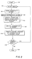
- Fig. 2 there is illustrated a flowchart of the process of determining the color of the illuminant which is implemented via software in the image processor.
- the software is input into the image processor either via a floppy disk or it may be stored on a hard disk or firmware of the image processor.
- the software is initiated S2 and the user selects a digital representation of an image for retrieval S4 which, as previously stated, is preferably a color digital image stored in. a multiple bit-per-pixel bitmap using three primary colors: red, green, and blue.
- a single bit-per-pixel chromaticity bitmap is then formed S6 in 7-space from the retrieved image by computing the chromaticity of every pixel in the image and placing a "1" bit in the chromaticity bitmap at the position corresponding to the chromaticity of each pixel in 7-space; a typical bitmap is illustrated in Fig. 3. As is well known in the art, a "0" bit is placed at each pixel in the chromaticity bitmap where there is no corresponding chromaticity in the retrieved image.
- a smoothed version of the chromaticity bitmap is then formed S8; a smoothed bitmap of Fig. 3 is shown in Fig. 4.
- Smoothing may be performed by any of a number of well-known techniques.
- the chromaticity bitmap may be converted to a grayscale bitmap and, for each pixel in it, its value is replaced by the sum of the neighboring pixels at a distance of 3 in every direction (left, right, up, down) divided by 49, thereby blurring the image.
- a fixed threshold value is then applied to the resulting pixels, such that all those pixels above threshold are set to 1 and all those below are set to 0.
- the blur-threshold process may be repeated until the desired smoothness is attained.
- the smoothed bitmap includes objects thereon, one of which is typically significantly larger in size than the other objects.
- the large object is used in determining the chromaticity of the illuminant as discussed in detall below.
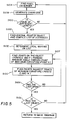
- a subroutine S10 is then performed for identifying a plurality of "spokes” in the smoothed chromaticity bitmap and for, thereafter, projecting a series of "beams” across the bitmap at the spoke positions.
- This subroutine is illustrated by the flowchart of FIG. 5.
- the chromaticity bitmap is scanned raster-fashion (line by line, preferably starting at the lower-left corner) until a non-zero pixel is encountered S10A for finding an object thereon.
- a chaincode representation of the object of which this pixel (that is, initially identified pixel) is a part is then created S10B for the identified object.
- the generation of a chaincode is a process well-known in the art; however, it will be briefly described herein for clarity.
- the pixels surrounding the initially identified pixel are sequentially searched until another non-zero pixel is encountered, and a directional digit is assigned for indicating the direction of this recently found pixel from the initially identified pixel which-was found. For example, if the recently found pixel is substantially 45 degrees from the original pixel, a "2" is assigned as a directional digit, and if the recently found pixel is substantially 90 degrees from the original pixel, a "3" is assigned as a directional digit.
- the generation of the chaincode is continued by using the pixel which was immediately assigned a directional digit as the reference location for beginning the search and the above-described process is repeated until the original pixel is found which indicates the entire object is now in chaincode form.
- the length of the chaincode is then checked S10C to verify that the object described is of sufficient size to be considered significant, preferably 100 pixels in length. If not, the raster-fashion search is continued beginning at the pixel on the object with highest vertical position for finding the next object, and the above-described process is repeated.
- a point near its center is established S10D by computing the average of the minimum and maximum points on the object in the x- and y- directions, assuming a hypothetical Cartesian coordinate system is used.
- This "central point” a used to compute a “distance list” by measuring the distance (L) between it and every point along the perimeter of the object as characterized by its chaincode, as illustrated in FIG. 7.
- a graphical representation of a typical distance list is illustrated in which the initially identified pixel on the perimeter of the object is assigned a zero on the abscissa and the adjacent pixels as sequentially located in the chaincode are, correspondingly, sequentially numbered thereafter.
- the ordinate is the distance of the pixel from the central point.
- four points, located in the comers of the rectangular box bounding the object may be used in lieu of the single central point, each corner as a reference point for measuring the distance to each pixel on the object.
- the graphs created from each reference corner are then merged, as is well known in the art, for creating a single graph. This method, however, increases computational time.
- each local maximum (A, B, C and D) from the distance list is identified S10E.
- This may be done using a number of different search techniques known in the art.
- the graphical representation of the distance the list which is a monotonic curve, is traversed starting preferably at the left end and the slope is computed at each point. The curve is traversed as long as the slope is positive. When the slope changes sign, that point is saved as a potential local maximum.
- the difference between it and a second point at a fixed distance back along the curve, preferably 20 pixels leftwardly on the curve is computed. If this difference is greater then zero, the potential maximum point is considered acceptable as a "spoke" and is saved into memory on a list of local maxima. This process is repeated for the entire distance list curve for finding each maximum or "spoke.”
- the local maxima (A, B, C and D) on the graph correspond to the points of maximum curvature on the perimeter of the current object in the smoothed chromaticity bitmap and therefore also represent the endpoints of the spokes in the object. Once they have been found, the beam boundaries may be computed. This process is illustrated in Fig. 9.
- the curvature of the perimeter of the object in the vicinity of the spoke endpoint is examined and two points are selected, one on each side of the spoke endpoint where the curvature begins to significantly decrease relative to the curvature at the spoke endpoint, for example points G and H in Fig. 9 (S10G). This process is repeated for each spoke in the object S10H.
- the search of the smoothed chromaticity bitmap continues for additional objects as described above S10I. If no additional suitable objects are found, the method continues with the next step.
- the next step is to project all of the beams found for all of the objects all the way across the entire smoothed chromaticity bitmap such that they intersect S12. Then the area bounded between the "maximum beam intersection set" is computed as follows.
- the entire chromaticity bitmap is again scanned raster fashion (again preferably starting at the lower-left corner) and the coordinates of each point are tested against every mated pair of beam edges to determine if it is between a mated pair of beam edges; that is, whether it is to the right of a left beam edge and to the left of a right beam edge (where left and right are relative to an observer positioned at the spoke endpoint facing toward the beam endpoints).
- a counter is incremented for every mated pair of beam edges between which a given point is disposed. If the count reaches a value equal to the number of total number of beams ,that point is saved as a member of a "maximum beam intersection set.”
- the testing process is repeated, decrementing the intersection threshold by one each time until a non-zero intersection set is found. If an intersection is not located, the central point ( point A of Fig. 7) is returned as the illuminant point.
- This "maximum beam intersection set” thus forms a polygon describing the smallest region in which the most beams intersect.
- the final step in the method is to compute a measure of central tendency of this polygon S14.
- the centroid of the polygon may be used.
- the coordinates of the computed central point 50 represent the chromaticity of the illuminant in T-space of the original color image.
- the user may then either select another image S16 for repeating the abovedescribed steps, or exit S18 the program.
Landscapes
- Engineering & Computer Science (AREA)
- Multimedia (AREA)
- Signal Processing (AREA)
- Physics & Mathematics (AREA)
- General Physics & Mathematics (AREA)
- Theoretical Computer Science (AREA)
- Software Systems (AREA)
- Image Analysis (AREA)
Applications Claiming Priority (2)
| Application Number | Priority Date | Filing Date | Title |
|---|---|---|---|
| US766135 | 1996-12-17 | ||
| US08/766,135 US5825916A (en) | 1996-12-17 | 1996-12-17 | Illuminant color detection |
Publications (1)
| Publication Number | Publication Date |
|---|---|
| EP0849935A2 true EP0849935A2 (fr) | 1998-06-24 |
Family
ID=25075515
Family Applications (1)
| Application Number | Title | Priority Date | Filing Date |
|---|---|---|---|
| EP97203831A Withdrawn EP0849935A2 (fr) | 1996-12-17 | 1997-12-05 | Détermination de la couleur de la source de lumière |
Country Status (3)
| Country | Link |
|---|---|
| US (1) | US5825916A (fr) |
| EP (1) | EP0849935A2 (fr) |
| JP (1) | JPH10187972A (fr) |
Families Citing this family (9)
| Publication number | Priority date | Publication date | Assignee | Title |
|---|---|---|---|---|
| KR100237284B1 (ko) * | 1997-04-28 | 2000-01-15 | 윤종용 | 화상신호로부터 조명색을 검출하는 방법 |
| KR100304663B1 (ko) * | 1998-12-04 | 2001-09-29 | 윤종용 | 칼라조명색온도검출방법및장치 |
| KR100311075B1 (ko) * | 1999-11-15 | 2001-11-14 | 윤종용 | 인지광원과 하이라이트를 이용한 조명 색도 추정 및변환장치 및 그를 위한 방법 |
| US20020196972A1 (en) * | 2001-06-26 | 2002-12-26 | Gokalp Bayramoglu | Color correction for color devices based on illuminant sensing |
| US7057768B2 (en) * | 2001-07-02 | 2006-06-06 | Corel Corporation | Automatic color balance |
| US7009733B2 (en) * | 2001-07-02 | 2006-03-07 | Coral Corporation | Manual correction of an image color |
| US8055063B2 (en) * | 2003-09-30 | 2011-11-08 | Sharp Laboratories Of America, Inc. | Methods and systems for improving robustness of color balance correction |
| US20060104537A1 (en) * | 2004-11-12 | 2006-05-18 | Sozotek, Inc. | System and method for image enhancement |
| US11856331B1 (en) * | 2017-05-10 | 2023-12-26 | Waylens, Inc. | Extracting and transmitting video analysis metadata for a remote database |
Family Cites Families (4)
| Publication number | Priority date | Publication date | Assignee | Title |
|---|---|---|---|---|
| US4685071A (en) * | 1985-03-18 | 1987-08-04 | Eastman Kodak Company | Method for determining the color of a scene illuminant from a color image |
| US5131058A (en) * | 1990-08-24 | 1992-07-14 | Eastman Kodak Company | Method for obtaining output-adjusted color separations |
| US5416890A (en) * | 1991-12-11 | 1995-05-16 | Xerox Corporation | Graphical user interface for controlling color gamut clipping |
| US5680327A (en) * | 1995-03-21 | 1997-10-21 | Light Source Computer Images, Inc. | Apparatus and process for a digital swatchbook |
-
1996
- 1996-12-17 US US08/766,135 patent/US5825916A/en not_active Expired - Fee Related
-
1997
- 1997-12-05 EP EP97203831A patent/EP0849935A2/fr not_active Withdrawn
- 1997-12-16 JP JP9346456A patent/JPH10187972A/ja active Pending
Also Published As
| Publication number | Publication date |
|---|---|
| JPH10187972A (ja) | 1998-07-21 |
| US5825916A (en) | 1998-10-20 |
Similar Documents
| Publication | Publication Date | Title |
|---|---|---|
| EP0778543B1 (fr) | Méthode basée sur le gradient pour estimer les valeurs d'éléments d'image inconnus dans une image numérisée | |
| US7342572B2 (en) | System and method for transforming an ordinary computer monitor into a touch screen | |
| US7218773B2 (en) | Pose estimation method and apparatus | |
| US6768509B1 (en) | Method and apparatus for determining points of interest on an image of a camera calibration object | |
| JP2776295B2 (ja) | 画像インデックス生成方法及び画像インデックス生成装置 | |
| US6898316B2 (en) | Multiple image area detection in a digital image | |
| US7313289B2 (en) | Image processing method and apparatus and computer-readable storage medium using improved distortion correction | |
| JP3684017B2 (ja) | 画像処理装置及び方法 | |
| US20040218832A1 (en) | Method for adjusting the brightness of a digital image utilizing belief values | |
| EP0768621A2 (fr) | Méthode et appareil pour corriger des valeurs de pixels dans une image numérique | |
| US20040184670A1 (en) | Detection correction of red-eye features in digital images | |
| EP1638345A1 (fr) | Procede de calcul de donnees de correction de caracteristiques d'affichage, programme de calcul de donnees de correction de caracteristiques d'affichage et dispositif de calcul de donnees de correction de caracteristiques d'affichage | |
| CN109002823B (zh) | 一种感兴趣区域确定方法、装置、设备及可读存储介质 | |
| KR20070008652A (ko) | 촬영된 이미지로부터 원 데이터를 추출하는 방법 | |
| EP2782065B1 (fr) | Dispositif de traitement d'image pour retirer des lignes d'encerclement afin d'identifier des sous-régions de l'image | |
| US5825916A (en) | Illuminant color detection | |
| US6115078A (en) | Image sharpness processing method and apparatus, and a storage medium storing a program | |
| US8055065B2 (en) | Vectorisation of colour gradients | |
| US5986771A (en) | Method for computing a control signal for combining digital images | |
| US6304672B1 (en) | Edge detecting method and edge detecting device which detects edges for each individual primary color and employs individual color weighting coefficients | |
| US20050248664A1 (en) | Identifying red eye in digital camera images | |
| US5778105A (en) | Method of and apparatus for removing artifacts from a reproduction | |
| JP2005184685A (ja) | 画像処理装置、プログラムおよび記録媒体 | |
| JP3199009B2 (ja) | 画像蓄積・管理装置及び画像インデックス生成方法 | |
| JPH06168331A (ja) | パターンマッチング方法 |
Legal Events
| Date | Code | Title | Description |
|---|---|---|---|
| PUAI | Public reference made under article 153(3) epc to a published international application that has entered the european phase |
Free format text: ORIGINAL CODE: 0009012 |
|
| AK | Designated contracting states |
Kind code of ref document: A2 Designated state(s): AT BE CH DE DK ES FI FR GB GR IE IT LI LU MC NL PT SE |
|
| AX | Request for extension of the european patent |
Free format text: AL;LT;LV;MK;RO;SI |
|
| STAA | Information on the status of an ep patent application or granted ep patent |
Free format text: STATUS: THE APPLICATION HAS BEEN WITHDRAWN |
|
| 18W | Application withdrawn |
Withdrawal date: 19990510 |