The present invention refers to a radiator, specifically for household use, of the kind
consisting of a plurality of heating elements, each comprising a manifold element
and at least a radiant element which can be connected together, the manifold
element being obtained by a pressure die-sting process.
Household radiators are conventionally obtained by connecting in series a plurality
of heating bodies obtained by casting, wherein either water or fluid used as thermal
energy vectors is flowing. Said heating shells generally consist of a plurality of
upright pipes acting as radiant elements, which perform thermal exchange with the
environment; said upright pipes end in hollow manifold elements, usually having a
large diameter hole in a middle position. Arranging a plurality of heating elements in
series and connecting them through said holes in the manifolds, two ducts are
obtained, an upper one and a lower one, where the upper duct usually represents
the fluid inlet pipe to the radiator, whereas the lower duct acts as an outlet pipe.
The manifold holes which realize each duct are usually coupled by threaded
connectors, whereas the end elements are either closed with pierced or holed
threaded taps of the so-called 'GAS' type, which allow for the coupling of the water
conduits, or by means of blind plugs.
Sectional or composable radiators are also known, wherein the manifold elements
and the heating pipes of one same heating body are manufactured separately and
then coupled to each other.
Said coupling is usually done by welding the pipes on proper protrusions available
on the manifold elements or through other known processes.
Thus, high flexibility can be reached for the type of materials and processes to be
used to execute the manifold elements and radiant elements, which may differ from
each other with consequent economical and technical benefits. For instance, the
manifold elements can be obtained through cast-iron, being highly resistant to
corrosion, and the radiant elements made of compressive bent steel sheet, with a
good radiant power and low production costs.
In particular, quite recently the use of aluminium and similar materials has proved
satisfactory for the execution of radiators. Aluminium is a light material withstanding
corrosion, specially suitable for household environments.
Therefore, manufacture of aluminium manifold elements appears quite beneficial,
specifically by pressure die-casting process, i.e. a casting procedure where the
mould is filled through the pressure exerted by a compressive element on the molten
metal. Against conventional casting processes, such as those using a so-called
'shell' mould and cores, pressure die-casting will allow achievement of castings in
series with a high dimensional exactness. As a result, for instance, external finishing
of the part is improved since, under the compressive action, metal will better adhere
to the mould walls. This technique applies specifically to alloys with a low melting
point, such as aluminium alloys, or the brass, and when used for large series
productions, it allows for considerably abating manufacturing costs.
From the German patent DE3622266 is known, for instance, a manifold element
made of die-cast aluminum. Said manifold element is achieved through pressure
die-casting of two half-elements, which are then connected to each other by laser
welding.
This procedure has a considerable drawback concerning the manufacturing cost of
the manifold element, since the equipment required for laser welding are quite
expensive.
Other radiators are also known, where the manifold element is obtained by pressure
die-casting in one piece alone. However, said radiators have a limited radiant power,
as they can only have one radiant element or, at most, two radiant elements with a
round section. This is due to the fact that, according to the known state of art, it is
not possible to obtain single heating elements having three or more radiant columns
with a round suction, since of said radiator geometry, which hinders an efficient
pressure die-casting process of the manifold element, as it will be butter clarified in
the following.
Therefore, said radiators nave the drawback of limiting both the radiant surface and
flowrate of each heating element, as two round suction columns can be used at the
most. To increase their radiant power, the radius of the round section of the columns
may be eventually increased, but this requires a considerable increase of the
radiator overall dimensions, with the result of only a moderate increase of the radiant
power. Moreover, this solution also has a drawback concerning the appearance of
the radiator, inasmuch as it will differ from a typical design of a steel radiator, such
as for instance the one shown in Fig. 1a, said design being widely known and
accepted by final users and both the architects and interiors decorators for their
integration into household environments.
It is the object of the present invention to solve the above drawbacks and provide a
radiator, specifically for household use, whose manifold element is obtained by
pressure die-casting process and has an improved manufacture in respect to the
known solutions.
Within this frame, it is the main object of the present invention to provide a radiator,
specifically for household use, whose manifold element is obtained by pressure die-casting
process and is manufactured in a simple and cheap way.
A further object of the present invention is to provide a radiator, specifically for
household use, whose manifold element is manufactured by pressure die-casting
process and is not subject to surface and volume limitations related to the radiant
elements.
A further object of the present invention is to provide a radiator, specifically for
household use, whose manifold element is manufactured by a pressure die-casting
process, whose aesthetic appearance after installation is substantially similar to that
of equivalent radiators manufactured by pressure die-casting and with improved
external finishing.
To reach such purposes it is the object of the present invention a radiator,
specifically for household use, incorporating the features of the annexed claims,
which form integral part of the present description.
Further purposes, characteristics and advantages of the present invention will
become apparent from the following detailed description and annexed drawings,
which are only supplied by way of a non limiting example, wherein:
- Fig. 1a shows schematically a possible embodiment of a radiator according to the
known state of the art;
- Fig. 1b shows schematically a detail of the radiator represented in Fig. 1a;
- Fig. 1c shows schematically a change of the detail represented in Fig. 1b;
- Fig. 2 shows a partial section of the change represented in Fig. 1c;
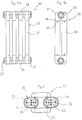
- Fig. 3a shows schematically a radiator according to the present invention;
- Fig. 3b shows schematically a detail of the radiator represented in Fig. 3a;
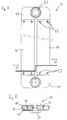
- Fig. 4 shows a partial section of the detail represented in Fig. 3b.
- Fig. 5 shows a second section of the detail represented in Fig. 3b;
- Fig. 6 shows a third section of the detail represented in Fig. 3b;
- Fig 7 shows schematically a detail of the radiator according to a possible variant
embodiment of the present invention;
- Fig. 8 shows a section of the detail represented in Fig. 7, according to the axis A-A of said figure.
Fig. 1a shows a front view of a radiator 1, according to the known state of art,
consisting of a plurality of heating elements 2, formed by columns 3, usually having
a substantially round section, which realize radiant elements, and headers 4 used as
manifold elements. The heating elements 2 are arranged in cascade, so that the
headers 4 with holes 5 (as it can be seen in Figs. 1b and 1c) define an upper duct
and a lower duct 7 for the throughflow of the heating fluid. Fig. 1b shows a side view
of a heating element having two columns 8, whereas Fig. 1c shows a front view of a
heating element having three columns 9.
Fig. 2 shows a partial section of a heating element having three columns 9 of a
radiator 1 according to the known state of art. The header 4 has some hollow
protrusions 10, one for each column 3 to be connected. Said protrusions 10 are
provided with housings 11 for sealing rings 12. The column 3 is mechanically
fastened at point 13, after its engagement on protozoon 10. Therefore, the header 4
has four openings, i.e. three protrusions 10 and the hole 5 either on the upper duct 6
or lower duct 7. During a hypothetical manufacturing process of the header 4 by
pressure die-casting, some compressive elements, not shown here, would be
introduced in a mould, also not represented here, through protrusions 10 and the
hole 5, to exert a pressure on the molten metal. Since said compressive elements
would only be allowed a straight motion, such a compressive action cannot be
exerted in some areas 14 of the header 4; and the metal contained in the pressure
die-casting mould will not be flown along the mould nor discharged outside. As a
result, in the best of instances, a header 4 might contain a large quantity of excess
material, or even communication between the hole 5 and protrusions 10, and
consequently columns 3, could be obstructed.
On the contrary, Fig. 3a shows a front view of a radiator 30 according to the
invention. Said radiator 30 consists of a plurality of heating elements 15
interconnected by known means. Said heating elements 15 consist of columns 16
and headers 17. Said heating elements 15 are connected in cascade, so that the
headers 17 form an upper duct 28 and a lower duct 29, which intercommunicate
through holes 23. As it can be seen in this view, the appearance of the radiator 30 is
substantially similar to the one of the radiator 1 shown in Fig. 1a.
Fig. 3b shows a side view of a heating element 15 of the radiator 30. Said heating
element 15 has two headers 17, having two protrusions 18 connected with two
columns 16. In this view, both the columns 16 and protrusions 18 appear to extend
horizontally over most of the header width 17, compared to protrusions 10 and
columns 3 of Fig. 2, so obtaining a uniform profile between the headers 17 and the
columns 16.
Fig. 4 represents the heating element 15, through a view where a column 16 is
partially sectioned and the other column 16 removed. Protrusions 18 have
substantially an internal ellipsoidal section, as better shown in Fig. 5, and columns
16 have a corresponding internal section. Protrusions 18 of headers 17 have
housings 19 to accept sealing elements 20, which have an ellipsoidal configuration
in this instance. Protrusions 18 have recesses 21 for realizing a mechanical coupling
of columns 16 with headers 17 through a deformation 22 of the edge of the column
16 on the recess 21. The header 17 has a hole 23 to let the header 17 communicate
with the remaining headers 17 of the other heating elements 15 and obtain both the
higher duct 28 and lower duct 29. As it can be seen in the sectioned column 16, the
protozoon 18 is defining inside it a duct 24, said duct 24 going on through the
header 17 to intersect the hole 23.
Said duct 24 is formed during the pressure die-casting process, by introducing a
properly shaped compressive element, i.e. having an ellipsoidal section, into the
mould, inside the protozoon 18. During the pressure die-casting process, another
compressive element is introduced inside the hole 23 - which during the casting of
the molten metal will be substantially tangential to the compressive element defining
the duct 24 or have a small interfering degree - the material will be completely
discharged out of the mould in the areas involved. As it is apparent from a
comparison between Figs. 2 and 4 attached hereto, according to the invention, the
area 14 that according to the known state of the art would have hindered a discharge
of the molten metal is removed, due to an interference between the duct 24 and the
hole 23.
Fig. 5 shows a front view of the heating element 15 of Fig. 4 partially in section,
where the sealing element 20 located in the housing 19 can be seen, and above it
the recess 21 on protozoon 18 coupled with the column 16 through the deformation
22. During assembly, as it can be seen looking to protozoon 18 in section, each
column 16 is coupled engaging it on protozoon 18, as a female part of a male-female
coupling, where the male is constituted by protozoon 18. The internal surface of the
column 16 and the outside surface of the protozoon 18 have such dimensions to
allow their coupling, with the exception of the area on the protozoon 18 where
recesses 21 are located. The column 16 is engaged on the protozoon 18 and stops
against a shoulder 27 obtained on the protozoon 18. Thus, the seal ring 20 results in
being compressed between the column 16 and the housing 19 obtained on the
protozoon 18. After the column 16 is engaged on the protozoon 18, deformation 22
is made through a proper spherical punching device on the column 16 in line with
recesses 21 on the protozoon 18. Therefore, the wall of the column 16 enters the
recesses 21 to form deformations 22 and warranting a mechanical coupling between
the columns 16 and the headers 17.
Fig. 6 shows a view of the header 17 where the configuration of protrusions 18 can
be seen. Said protrusions 18 have an internal section with an ellipsoidal
configuration, i.e. characterized by a longer dimension D1 and a shorter dimension
D2. In this way, using a shorter dimension D2 corresponding to the diameter of the
usual columns 3 with round section shown in Figs. 1 and 2, a size of the heating
element 15 for connection in series with other heating elements 15 equal to the size
of the heating element 9 shown in Fig. 2 can be obtained. The longer dimension D1
can be chosen so that the two columns 16 have a total surface and/or volume
substantially dual to the total one of the three columns 3 shown in Fig. 2. Thus, a
radiator similar to the one shown in Fig. 1 can be obtained both from a functional
and appearance viewpoint, characterized in that the header 17 is advantageously
obtained by pressure die-casting in one piece.
Said ducts 24 with a substantially ellipsoidal configuration, being necessary for the
discharge of the material during the pressure die-casting process, are obtained, with
the aid of proper compressive elements having a corresponding ellipsoidal section,
during the pressure die-casting process.
The characteristics of the present invention are clear from the above description as
also its advantages appear to be evident.
The radiator described by way of example can be obtained using a pressure die-casting
process, to manufacture the manifold element, with a considerable cost
reduction compared to the usual manifold elements manufactured by casting.
Aluminium alloys as well as for example copper alloys or other materials suitable for
pressure die-casting process can be used.
Using two columns with an ellipsoidal or rectangular section, the same total surfaces
and/or volumes as developed by round multi-column radiators can be obtained (for
which however the pressure die-casting process cannot be used), by binding the
number of radiator columns to the longer diameter D1 of the columns section
according to the invention.
The outside appearance after installation of the radiator according to the invention is
similar to any conventional radiators obtained by steel casting, which means that
said radiator can replace them for any architectural project without aesthetic
changes.
The use of ellipsoidal or ovalized sections, in the specific instance previously
described where the coupling between radiant elements and manifold elements
occurs mechanically and the column is deformed by a punching device on a recess
of the manifold element protozoon, will ensure a flat surface instead of a cylindrical
surface for the punching operation and ensure improved precision and sealing of the
mechanical coupling.
The radiator described by way of example is specifically of a simple and fast
realization, from the mechanical working viewpoint, also after the pressure die-casting
of the manifold elements, in that a spherical punching device for assembly is
simply required. A gasket or seal ring placed between the internal wall of the
columns and the housing on the protozoon of the manifold elements ensures
hydraulic sealing in a similar simple manner as well as fast assembly.
Finally, the materials to be used can be freely selected, so as to enhance the
functional characteristics of each element. Once a suitable material for the pressure
die-casting of the manifold elements is selected, other materials for the radiant
elements can be chosen for improving the radiant and thermal exchange properties,
such as for example steel alloys, processed as extruded or die-folded laminated
welded pipes (about 430 W/m2 radiant power), or copper alloys (750 W/m2) for a still
higher radiant capacity.
It is apparent that many changes are possible for the man skilled in the art to the
radiator, specifically for household use, described by way of example, without
departing from the novelty spirit of the innovative solution, and it is also clear that in
practical actuation of the invention the components might be different in form and
size from the ones described, and be replaced with technical equivalent elements.
According to a possible embodiment, the columns may be bound to the manifold
elements by welding or other known coupling means, such as for instance
mechanical forced couplings or use of bolts.
The internal section of the protrusions and manifold elements may differ, e.g. be
rectangular instead of ellipsoidal, but it can generally take any configuration
consisting of two main orthogonal axis, one of them being substantially longer than
the other.
Figs. 7 and 8 represent a possible variant embodiment of the present invention; the
same reference numbers of the previous figures are used in them, to indicate
technically equivalent elements.
As it can be seen from the section of Fig. 8, according to the suggested variant
embodiment, columns 16 have a rib or internal baffle indicated with N over a large
part of their development; said rib N is not present in the portion of the columns 16
provided for the engagement on protrusions 18 (Fig. 4)
The rib N is suitable to connect two parallel sides of the column 16 (specifically, the
sides parallel to the length or dimension D1), with the aim of strengthening the
structure thereof; in this way, any deformation risk for the columns 16 can be
avoided, which may be possibly due to high hydraulic pressures in the system
wherein the radiator is incorporated, above all in those cases where the section of
columns 16 have a length or dimension D1, which is 1,5 times higher compared to
the length or dimension D2.
In Fig. 7 it is also possible to see how deformations 22 on columns 16 (obtained in
correspondence with recesses 21) may be more in number than previously shown
with reference to Figs. 3-5; also this variant embodiment appears to be particularly
useful in the case of those columns 16 where the length or dimension D1 exceeds by
1,5 times the length or dimension D2.