EP0851202A2 - Radiateur obtenu au-moins en partie par moulage sous pression - Google Patents
Radiateur obtenu au-moins en partie par moulage sous pression Download PDFInfo
- Publication number
- EP0851202A2 EP0851202A2 EP97122610A EP97122610A EP0851202A2 EP 0851202 A2 EP0851202 A2 EP 0851202A2 EP 97122610 A EP97122610 A EP 97122610A EP 97122610 A EP97122610 A EP 97122610A EP 0851202 A2 EP0851202 A2 EP 0851202A2
- Authority
- EP
- European Patent Office
- Prior art keywords
- radiator
- manifold
- elements
- household use
- pressure die
- Prior art date
- Legal status (The legal status is an assumption and is not a legal conclusion. Google has not performed a legal analysis and makes no representation as to the accuracy of the status listed.)
- Withdrawn
Links
- 238000004512 die casting Methods 0.000 title claims abstract description 32
- 238000000034 method Methods 0.000 claims abstract description 29
- 238000010438 heat treatment Methods 0.000 claims abstract description 27
- 230000008569 process Effects 0.000 claims abstract description 23
- 239000000463 material Substances 0.000 claims description 11
- 238000003466 welding Methods 0.000 claims description 5
- 239000012530 fluid Substances 0.000 claims description 4
- 229910000838 Al alloy Inorganic materials 0.000 claims description 3
- 229910001369 Brass Inorganic materials 0.000 claims description 2
- 229910045601 alloy Inorganic materials 0.000 claims description 2
- 239000000956 alloy Substances 0.000 claims description 2
- 239000010951 brass Substances 0.000 claims description 2
- 238000005728 strengthening Methods 0.000 claims description 2
- 230000008878 coupling Effects 0.000 description 10
- 238000010168 coupling process Methods 0.000 description 10
- 238000005859 coupling reaction Methods 0.000 description 10
- 238000004519 manufacturing process Methods 0.000 description 8
- 238000005266 casting Methods 0.000 description 7
- 229910052751 metal Inorganic materials 0.000 description 6
- 239000002184 metal Substances 0.000 description 6
- 238000007789 sealing Methods 0.000 description 5
- 229910052782 aluminium Inorganic materials 0.000 description 4
- XAGFODPZIPBFFR-UHFFFAOYSA-N aluminium Chemical compound [Al] XAGFODPZIPBFFR-UHFFFAOYSA-N 0.000 description 4
- 238000004080 punching Methods 0.000 description 4
- 229910000831 Steel Inorganic materials 0.000 description 3
- 239000004411 aluminium Substances 0.000 description 3
- 230000008901 benefit Effects 0.000 description 3
- 239000010959 steel Substances 0.000 description 3
- 229910000881 Cu alloy Inorganic materials 0.000 description 2
- 230000009471 action Effects 0.000 description 2
- 230000008859 change Effects 0.000 description 2
- 238000005260 corrosion Methods 0.000 description 2
- 230000007797 corrosion Effects 0.000 description 2
- 238000009434 installation Methods 0.000 description 2
- XLYOFNOQVPJJNP-UHFFFAOYSA-N water Substances O XLYOFNOQVPJJNP-UHFFFAOYSA-N 0.000 description 2
- 229910000851 Alloy steel Inorganic materials 0.000 description 1
- 229910001018 Cast iron Inorganic materials 0.000 description 1
- 230000009286 beneficial effect Effects 0.000 description 1
- 235000014121 butter Nutrition 0.000 description 1
- 238000004891 communication Methods 0.000 description 1
- 230000009977 dual effect Effects 0.000 description 1
- 230000010354 integration Effects 0.000 description 1
- 230000002452 interceptive effect Effects 0.000 description 1
- 238000002844 melting Methods 0.000 description 1
- 230000008018 melting Effects 0.000 description 1
- 230000009467 reduction Effects 0.000 description 1
- 239000013598 vector Substances 0.000 description 1
Images


Classifications
-
- F—MECHANICAL ENGINEERING; LIGHTING; HEATING; WEAPONS; BLASTING
- F28—HEAT EXCHANGE IN GENERAL
- F28D—HEAT-EXCHANGE APPARATUS, NOT PROVIDED FOR IN ANOTHER SUBCLASS, IN WHICH THE HEAT-EXCHANGE MEDIA DO NOT COME INTO DIRECT CONTACT
- F28D1/00—Heat-exchange apparatus having stationary conduit assemblies for one heat-exchange medium only, the media being in contact with different sides of the conduit wall, in which the other heat-exchange medium is a large body of fluid, e.g. domestic or motor car radiators
- F28D1/02—Heat-exchange apparatus having stationary conduit assemblies for one heat-exchange medium only, the media being in contact with different sides of the conduit wall, in which the other heat-exchange medium is a large body of fluid, e.g. domestic or motor car radiators with heat-exchange conduits immersed in the body of fluid
- F28D1/04—Heat-exchange apparatus having stationary conduit assemblies for one heat-exchange medium only, the media being in contact with different sides of the conduit wall, in which the other heat-exchange medium is a large body of fluid, e.g. domestic or motor car radiators with heat-exchange conduits immersed in the body of fluid with tubular conduits
- F28D1/053—Heat-exchange apparatus having stationary conduit assemblies for one heat-exchange medium only, the media being in contact with different sides of the conduit wall, in which the other heat-exchange medium is a large body of fluid, e.g. domestic or motor car radiators with heat-exchange conduits immersed in the body of fluid with tubular conduits the conduits being straight
- F28D1/0535—Heat-exchange apparatus having stationary conduit assemblies for one heat-exchange medium only, the media being in contact with different sides of the conduit wall, in which the other heat-exchange medium is a large body of fluid, e.g. domestic or motor car radiators with heat-exchange conduits immersed in the body of fluid with tubular conduits the conduits being straight the conduits having a non-circular cross-section
- F28D1/05358—Assemblies of conduits connected side by side or with individual headers, e.g. section type radiators
-
- F—MECHANICAL ENGINEERING; LIGHTING; HEATING; WEAPONS; BLASTING
- F28—HEAT EXCHANGE IN GENERAL
- F28F—DETAILS OF HEAT-EXCHANGE AND HEAT-TRANSFER APPARATUS, OF GENERAL APPLICATION
- F28F21/00—Constructions of heat-exchange apparatus characterised by the selection of particular materials
- F28F21/08—Constructions of heat-exchange apparatus characterised by the selection of particular materials of metal
- F28F21/088—Constructions of heat-exchange apparatus characterised by the selection of particular materials of metal for domestic or space-heating systems
-
- F—MECHANICAL ENGINEERING; LIGHTING; HEATING; WEAPONS; BLASTING
- F28—HEAT EXCHANGE IN GENERAL
- F28F—DETAILS OF HEAT-EXCHANGE AND HEAT-TRANSFER APPARATUS, OF GENERAL APPLICATION
- F28F9/00—Casings; Header boxes; Auxiliary supports for elements; Auxiliary members within casings
- F28F9/02—Header boxes; End plates
-
- F—MECHANICAL ENGINEERING; LIGHTING; HEATING; WEAPONS; BLASTING
- F28—HEAT EXCHANGE IN GENERAL
- F28F—DETAILS OF HEAT-EXCHANGE AND HEAT-TRANSFER APPARATUS, OF GENERAL APPLICATION
- F28F9/00—Casings; Header boxes; Auxiliary supports for elements; Auxiliary members within casings
- F28F9/02—Header boxes; End plates
- F28F9/04—Arrangements for sealing elements into header boxes or end plates
- F28F9/16—Arrangements for sealing elements into header boxes or end plates by permanent joints, e.g. by rolling
- F28F9/165—Arrangements for sealing elements into header boxes or end plates by permanent joints, e.g. by rolling by using additional preformed parts, e.g. sleeves, gaskets
- F28F9/167—Arrangements for sealing elements into header boxes or end plates by permanent joints, e.g. by rolling by using additional preformed parts, e.g. sleeves, gaskets the parts being inserted in the heat-exchange conduits
-
- F—MECHANICAL ENGINEERING; LIGHTING; HEATING; WEAPONS; BLASTING
- F28—HEAT EXCHANGE IN GENERAL
- F28F—DETAILS OF HEAT-EXCHANGE AND HEAT-TRANSFER APPARATUS, OF GENERAL APPLICATION
- F28F9/00—Casings; Header boxes; Auxiliary supports for elements; Auxiliary members within casings
- F28F9/26—Arrangements for connecting different sections of heat-exchange elements, e.g. of radiators
- F28F9/262—Arrangements for connecting different sections of heat-exchange elements, e.g. of radiators for radiators
-
- F—MECHANICAL ENGINEERING; LIGHTING; HEATING; WEAPONS; BLASTING
- F28—HEAT EXCHANGE IN GENERAL
- F28D—HEAT-EXCHANGE APPARATUS, NOT PROVIDED FOR IN ANOTHER SUBCLASS, IN WHICH THE HEAT-EXCHANGE MEDIA DO NOT COME INTO DIRECT CONTACT
- F28D21/00—Heat-exchange apparatus not covered by any of the groups F28D1/00 - F28D20/00
- F28D2021/0019—Other heat exchangers for particular applications; Heat exchange systems not otherwise provided for
- F28D2021/0035—Other heat exchangers for particular applications; Heat exchange systems not otherwise provided for for domestic or space heating, e.g. heating radiators
Definitions
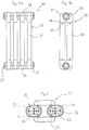
- Fig. 1a shows a front view of a radiator 1, according to the known state of art, consisting of a plurality of heating elements 2, formed by columns 3, usually having a substantially round section, which realize radiant elements, and headers 4 used as manifold elements.
- the heating elements 2 are arranged in cascade, so that the headers 4 with holes 5 (as it can be seen in Figs. 1b and 1c) define an upper duct and a lower duct 7 for the throughflow of the heating fluid.
- Fig. 1b shows a side view of a heating element having two columns 8
- Fig. 1c shows a front view of a heating element having three columns 9.
- Said duct 24 is formed during the pressure die-casting process, by introducing a properly shaped compressive element, i.e. having an ellipsoidal section, into the mould, inside the protozoon 18.
- a properly shaped compressive element i.e. having an ellipsoidal section
- another compressive element is introduced inside the hole 23 - which during the casting of the molten metal will be substantially tangential to the compressive element defining the duct 24 or have a small interfering degree - the material will be completely discharged out of the mould in the areas involved.
- the area 14 that according to the known state of the art would have hindered a discharge of the molten metal is removed, due to an interference between the duct 24 and the hole 23.
- the column 16 is engaged on the protozoon 18 and stops against a shoulder 27 obtained on the protozoon 18.
- the seal ring 20 results in being compressed between the column 16 and the housing 19 obtained on the protozoon 18.
- deformation 22 is made through a proper spherical punching device on the column 16 in line with recesses 21 on the protozoon 18. Therefore, the wall of the column 16 enters the recesses 21 to form deformations 22 and warranting a mechanical coupling between the columns 16 and the headers 17.
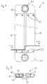
- Fig. 6 shows a view of the header 17 where the configuration of protrusions 18 can be seen.
- Said protrusions 18 have an internal section with an ellipsoidal configuration, i.e. characterized by a longer dimension D1 and a shorter dimension D2.
- a shorter dimension D2 corresponding to the diameter of the usual columns 3 with round section shown in Figs. 1 and 2
- a size of the heating element 15 for connection in series with other heating elements 15 equal to the size of the heating element 9 shown in Fig. 2 can be obtained.
- the longer dimension D1 can be chosen so that the two columns 16 have a total surface and/or volume substantially dual to the total one of the three columns 3 shown in Fig. 2.
- a radiator similar to the one shown in Fig. 1 can be obtained both from a functional and appearance viewpoint, characterized in that the header 17 is advantageously obtained by pressure die-casting in one piece.
- the radiator described by way of example can be obtained using a pressure die-casting process, to manufacture the manifold element, with a considerable cost reduction compared to the usual manifold elements manufactured by casting.
- the outside appearance after installation of the radiator according to the invention is similar to any conventional radiators obtained by steel casting, which means that said radiator can replace them for any architectural project without aesthetic changes.
- the radiator described by way of example is specifically of a simple and fast realization, from the mechanical working viewpoint, also after the pressure die-casting of the manifold elements, in that a spherical punching device for assembly is simply required.
- a gasket or seal ring placed between the internal wall of the columns and the housing on the protozoon of the manifold elements ensures hydraulic sealing in a similar simple manner as well as fast assembly.
- the materials to be used can be freely selected, so as to enhance the functional characteristics of each element.
- a suitable material for the pressure die-casting of the manifold elements is selected, other materials for the radiant elements can be chosen for improving the radiant and thermal exchange properties, such as for example steel alloys, processed as extruded or die-folded laminated welded pipes (about 430 W/m 2 radiant power), or copper alloys (750 W/m 2 ) for a still higher radiant capacity.
Landscapes
- Engineering & Computer Science (AREA)
- Physics & Mathematics (AREA)
- Thermal Sciences (AREA)
- Mechanical Engineering (AREA)
- General Engineering & Computer Science (AREA)
- Moulds For Moulding Plastics Or The Like (AREA)
- Steam Or Hot-Water Central Heating Systems (AREA)
Applications Claiming Priority (2)
| Application Number | Priority Date | Filing Date | Title |
|---|---|---|---|
| ITTO961079 | 1996-12-23 | ||
| ITTO961079 IT1289799B1 (it) | 1996-12-23 | 1996-12-23 | Radiatore ottenuto almeno in parte per pressofusione. |
Publications (2)
| Publication Number | Publication Date |
|---|---|
| EP0851202A2 true EP0851202A2 (fr) | 1998-07-01 |
| EP0851202A3 EP0851202A3 (fr) | 1999-06-30 |
Family
ID=11415152
Family Applications (1)
| Application Number | Title | Priority Date | Filing Date |
|---|---|---|---|
| EP97122610A Withdrawn EP0851202A3 (fr) | 1996-12-23 | 1997-12-22 | Radiateur obtenu au-moins en partie par moulage sous pression |
Country Status (2)
| Country | Link |
|---|---|
| EP (1) | EP0851202A3 (fr) |
| IT (1) | IT1289799B1 (fr) |
Cited By (2)
| Publication number | Priority date | Publication date | Assignee | Title |
|---|---|---|---|---|
| WO2007049104A1 (fr) * | 2005-10-25 | 2007-05-03 | K Delta Kalor S.R.L. | Procede de production destine aux radiateurs |
| WO2010131272A1 (fr) * | 2009-05-12 | 2010-11-18 | Stiliac S.P.A. | Tête de distribution et de collecte pour radiateurs de chauffage avec tuyaux, et procédé de fabrication |
Citations (1)
| Publication number | Priority date | Publication date | Assignee | Title |
|---|---|---|---|---|
| DE3622266A1 (de) | 1985-07-30 | 1987-02-12 | Vaillant Joh Gmbh & Co | Verfahren zur herstellung eines waermetauschers aus aluminium und anwendung des waermetauschers als gusskesselglied |
Family Cites Families (9)
| Publication number | Priority date | Publication date | Assignee | Title |
|---|---|---|---|---|
| FR615135A (fr) * | 1925-09-11 | 1926-12-30 | Perfectionnements aux radiateurs | |
| US1737558A (en) * | 1927-07-22 | 1929-12-03 | Internat Radiator Corp | Temperature-changing unit |
| FR720551A (fr) * | 1930-07-30 | 1932-02-22 | Manuf Generale Metallurg | Perfectionnements aux appareils d'échange thermique avec collecteur |
| FR802061A (fr) * | 1935-05-14 | 1936-08-26 | Radiateur de chauffage central | |
| FR1201614A (fr) * | 1958-07-05 | 1960-01-04 | éléments composites de radiateurs de chauffage central | |
| FR1386752A (fr) * | 1964-02-28 | 1965-01-22 | Nouveau procédé de fabrication d'éléments de radiateurs de chauffage central | |
| DE1483526C3 (de) * | 1965-11-29 | 1979-01-04 | Mario Bologna Andreoli (Italien) | Werkstoff für TeUe einer Druckgießform zum Druckgießen von hohlen Werkstücken aus Leichtmetall |
| IT977937B (it) * | 1973-03-01 | 1974-09-20 | Davico Livio | Radiatori per impianti di riscaldamento |
| IT8648373A0 (it) * | 1986-08-08 | 1986-08-08 | Santoro Gennaro | Scambiatore termico |
-
1996
- 1996-12-23 IT ITTO961079 patent/IT1289799B1/it active IP Right Grant
-
1997
- 1997-12-22 EP EP97122610A patent/EP0851202A3/fr not_active Withdrawn
Patent Citations (1)
| Publication number | Priority date | Publication date | Assignee | Title |
|---|---|---|---|---|
| DE3622266A1 (de) | 1985-07-30 | 1987-02-12 | Vaillant Joh Gmbh & Co | Verfahren zur herstellung eines waermetauschers aus aluminium und anwendung des waermetauschers als gusskesselglied |
Cited By (6)
| Publication number | Priority date | Publication date | Assignee | Title |
|---|---|---|---|---|
| WO2007049104A1 (fr) * | 2005-10-25 | 2007-05-03 | K Delta Kalor S.R.L. | Procede de production destine aux radiateurs |
| EA011434B1 (ru) * | 2005-10-25 | 2009-02-27 | К ДЕЛЬТА Т КАЛОР С.р.л. | Способ изготовления отопительного радиатора |
| WO2010131272A1 (fr) * | 2009-05-12 | 2010-11-18 | Stiliac S.P.A. | Tête de distribution et de collecte pour radiateurs de chauffage avec tuyaux, et procédé de fabrication |
| CN102428337A (zh) * | 2009-05-12 | 2012-04-25 | 斯蒂莱卡股份有限公司 | 带有管的散热器的分配和收集头以及制造方法 |
| EA019174B1 (ru) * | 2009-05-12 | 2014-01-30 | Стилиак С.П.А. | Подводящий или отводящий коллектор отопительных трубчатых радиаторов и способ его изготовления |
| CN102428337B (zh) * | 2009-05-12 | 2014-10-22 | 斯蒂莱卡股份有限公司 | 带有管的散热器的分配和收集头以及制造方法 |
Also Published As
| Publication number | Publication date |
|---|---|
| IT1289799B1 (it) | 1998-10-16 |
| ITTO961079A1 (it) | 1998-06-23 |
| EP0851202A3 (fr) | 1999-06-30 |
Similar Documents
| Publication | Publication Date | Title |
|---|---|---|
| US6234238B1 (en) | Aluminum-alloy heat exchanger | |
| GB2270971A (en) | Oil cooler with water pipes passing through an oil tank | |
| AU2002217510B2 (en) | Layered heat exchangers | |
| AU6209699A (en) | Heat exchanger | |
| KR20060012610A (ko) | 열 교환기 하우징 및 시일 | |
| EP1613781B1 (fr) | Plaque de refroidissement pour paroi de four metallurgique | |
| EP0481154A1 (fr) | Radiateur bimétallique pour installations de chauffage de bâtiment | |
| EP0851202A2 (fr) | Radiateur obtenu au-moins en partie par moulage sous pression | |
| KR101445786B1 (ko) | 보일러용 열교환기 | |
| CN220556222U (zh) | 管路连接件 | |
| JP4164146B2 (ja) | 熱交換器、及びこれを用いたカー・エアコン | |
| EP0654647A1 (fr) | Tube à ailettes pour échangeur de chaleur | |
| EP0838654A2 (fr) | Radiateur modulaire | |
| JP4164145B2 (ja) | 熱交換器、及びこれを用いたカー・エアコン | |
| CN210826224U (zh) | 一种纵向折弯型铜冷却壁 | |
| CN109282675B (zh) | 套管式热交换器及其制造方法和模具 | |
| RU2779677C1 (ru) | Трубчатый радиатор | |
| JPH0914886A (ja) | 複式熱交換器 | |
| EP1239256A1 (fr) | Radiateur aver refroidisseur à huile intégré | |
| CN100513840C (zh) | 一种模块化金属水龙头 | |
| JP3336579B2 (ja) | ハウジングレス式オイルクーラのコア部 | |
| US3844255A (en) | Boiler and method of making same | |
| KR100600538B1 (ko) | 인너핀이 내장된 이중관형 열교환기 제조방법 | |
| JP2594343Y2 (ja) | オイルクーラ | |
| JPH0487726A (ja) | ハウジングレス式オイルクーラのコア部の製造方法 |
Legal Events
| Date | Code | Title | Description |
|---|---|---|---|
| PUAI | Public reference made under article 153(3) epc to a published international application that has entered the european phase |
Free format text: ORIGINAL CODE: 0009012 |
|
| AK | Designated contracting states |
Kind code of ref document: A2 Designated state(s): AT BE CH DE DK ES FI FR GB GR IE IT LI LU MC NL PT SE |
|
| AX | Request for extension of the european patent |
Free format text: AL;LT;LV;MK;RO;SI |
|
| PUAL | Search report despatched |
Free format text: ORIGINAL CODE: 0009013 |
|
| AK | Designated contracting states |
Kind code of ref document: A3 Designated state(s): AT BE CH DE DK ES FI FR GB GR IE IT LI LU MC NL PT SE |
|
| AX | Request for extension of the european patent |
Free format text: AL;LT;LV;MK;RO;SI |
|
| AKX | Designation fees paid | ||
| STAA | Information on the status of an ep patent application or granted ep patent |
Free format text: STATUS: THE APPLICATION IS DEEMED TO BE WITHDRAWN |
|
| 18D | Application deemed to be withdrawn |
Effective date: 19991231 |