EP0851249A1 - Werkzeug zur Verbindung einer Faser mit einer anderen Faser oder mit einem optischen Verbindungselement mittels eines Verbindungsmoduls - Google Patents
Werkzeug zur Verbindung einer Faser mit einer anderen Faser oder mit einem optischen Verbindungselement mittels eines Verbindungsmoduls Download PDFInfo
- Publication number
- EP0851249A1 EP0851249A1 EP97403179A EP97403179A EP0851249A1 EP 0851249 A1 EP0851249 A1 EP 0851249A1 EP 97403179 A EP97403179 A EP 97403179A EP 97403179 A EP97403179 A EP 97403179A EP 0851249 A1 EP0851249 A1 EP 0851249A1
- Authority
- EP
- European Patent Office
- Prior art keywords
- fiber
- connection
- module
- shaft
- fibers
- Prior art date
- Legal status (The legal status is an assumption and is not a legal conclusion. Google has not performed a legal analysis and makes no representation as to the accuracy of the status listed.)
- Withdrawn
Links
- 239000000835 fiber Substances 0.000 title claims abstract description 193
- 230000003287 optical effect Effects 0.000 title claims description 10
- 238000003776 cleavage reaction Methods 0.000 claims description 30
- 230000007017 scission Effects 0.000 claims description 30
- 230000009471 action Effects 0.000 claims description 21
- 230000003100 immobilizing effect Effects 0.000 claims description 20
- 238000013519 translation Methods 0.000 claims description 10
- 238000002788 crimping Methods 0.000 claims description 9
- 230000036961 partial effect Effects 0.000 claims description 7
- 238000000429 assembly Methods 0.000 claims description 3
- 230000005484 gravity Effects 0.000 claims description 3
- 238000003780 insertion Methods 0.000 claims description 2
- 230000037431 insertion Effects 0.000 claims description 2
- 238000012423 maintenance Methods 0.000 claims description 2
- 238000009434 installation Methods 0.000 claims 1
- 230000007246 mechanism Effects 0.000 abstract description 2
- 238000003825 pressing Methods 0.000 description 10
- 230000000295 complement effect Effects 0.000 description 9
- 239000010432 diamond Substances 0.000 description 9
- 229910003460 diamond Inorganic materials 0.000 description 8
- 238000005520 cutting process Methods 0.000 description 5
- 230000008859 change Effects 0.000 description 3
- 238000006073 displacement reaction Methods 0.000 description 3
- 210000003813 thumb Anatomy 0.000 description 3
- 238000013459 approach Methods 0.000 description 2
- 230000000694 effects Effects 0.000 description 2
- 238000005304 joining Methods 0.000 description 2
- 239000000463 material Substances 0.000 description 2
- 238000000034 method Methods 0.000 description 2
- 230000004048 modification Effects 0.000 description 2
- 238000012986 modification Methods 0.000 description 2
- 230000002093 peripheral effect Effects 0.000 description 2
- 238000002360 preparation method Methods 0.000 description 2
- 230000001737 promoting effect Effects 0.000 description 2
- 238000007493 shaping process Methods 0.000 description 2
- VHCQVGQULWFQTM-VOTSOKGWSA-N Rubone Chemical compound COC1=CC(OC)=CC(O)=C1C(=O)\C=C\C1=CC(OC)=C(OC)C=C1OC VHCQVGQULWFQTM-VOTSOKGWSA-N 0.000 description 1
- VHCQVGQULWFQTM-UHFFFAOYSA-N Rubone Natural products COC1=CC(OC)=CC(O)=C1C(=O)C=CC1=CC(OC)=C(OC)C=C1OC VHCQVGQULWFQTM-UHFFFAOYSA-N 0.000 description 1
- 206010044625 Trichorrhexis Diseases 0.000 description 1
- 238000005452 bending Methods 0.000 description 1
- 239000000969 carrier Substances 0.000 description 1
- 239000011248 coating agent Substances 0.000 description 1
- 238000000576 coating method Methods 0.000 description 1
- 238000009826 distribution Methods 0.000 description 1
- 230000008030 elimination Effects 0.000 description 1
- 238000003379 elimination reaction Methods 0.000 description 1
- 230000000670 limiting effect Effects 0.000 description 1
- 230000014759 maintenance of location Effects 0.000 description 1
- 239000002184 metal Substances 0.000 description 1
- 239000013307 optical fiber Substances 0.000 description 1
- 230000008569 process Effects 0.000 description 1
- 230000001681 protective effect Effects 0.000 description 1
- 230000002441 reversible effect Effects 0.000 description 1
- 229920005992 thermoplastic resin Polymers 0.000 description 1
Images




Classifications
-
- G—PHYSICS
- G02—OPTICS
- G02B—OPTICAL ELEMENTS, SYSTEMS OR APPARATUS
- G02B6/00—Light guides; Structural details of arrangements comprising light guides and other optical elements, e.g. couplings
- G02B6/24—Coupling light guides
- G02B6/36—Mechanical coupling means
- G02B6/38—Mechanical coupling means having fibre to fibre mating means
- G02B6/3801—Permanent connections, i.e. wherein fibres are kept aligned by mechanical means
- G02B6/3802—Assembly tools, e.g. crimping tool or pressing bench
-
- G—PHYSICS
- G02—OPTICS
- G02B—OPTICAL ELEMENTS, SYSTEMS OR APPARATUS
- G02B6/00—Light guides; Structural details of arrangements comprising light guides and other optical elements, e.g. couplings
- G02B6/24—Coupling light guides
- G02B6/245—Removing protective coverings of light guides before coupling
-
- G—PHYSICS
- G02—OPTICS
- G02B—OPTICAL ELEMENTS, SYSTEMS OR APPARATUS
- G02B6/00—Light guides; Structural details of arrangements comprising light guides and other optical elements, e.g. couplings
- G02B6/24—Coupling light guides
- G02B6/25—Preparing the ends of light guides for coupling, e.g. cutting
-
- G—PHYSICS
- G02—OPTICS
- G02B—OPTICAL ELEMENTS, SYSTEMS OR APPARATUS
- G02B6/00—Light guides; Structural details of arrangements comprising light guides and other optical elements, e.g. couplings
- G02B6/24—Coupling light guides
- G02B6/36—Mechanical coupling means
- G02B6/38—Mechanical coupling means having fibre to fibre mating means
- G02B6/3801—Permanent connections, i.e. wherein fibres are kept aligned by mechanical means
Definitions
- the invention relates to a tool intended to ensure all of the operations required to connect one end of a fiber, or another fiber, either to an optical connector element via a connection module comprising a receiver box allowing a introduction of fiber at at least one end and means for fixing fiber (s) by wedging at the bottom of the housing which are implemented by depression.
- connection at the end of one or two fibers optical involves carrying out delicate operations including particular shaping of the end of each fiber to be connected in tip, precise positioning of the end (s) to ensure quality optical continuity and joining of each fiber after a adequate positioning.
- connection modules and in particular a splice allowing precise positioning of the fibers to be connected at the end and the fibers to be joined after positioning.
- connection of fibers using such modules does not does not dispense with carrying out the prior operations mentioned above, even if possible, these modules facilitate some.
- the invention therefore provides a connection tool designed to allow the execution of the sequence of operations necessary for the connection at the end of a fiber to another fiber or to an optical connector element by means of a receiver box connection module allowing introduction of fiber at at least one end and means for fixing it fiber (s) used by driving in, the tool being intended to ensure the following of these continuous operations after a first positioning of the fibers and the connection module on the tool.
- this tool includes means making it possible to carry out successively and possibly so simultaneous for two fibers, partial stripping of each fiber, cleavage end for end connection, positioning of each fiber cleaved in the module where it is connected, and a crimping of each fiber in connection position in the module, in a cycle controlled by rotation continuous of determined direction of a rotary control shaft comprised by the tool, after manual placement of each fiber and the module in determined positions on the tool.
- FIGS. 1 to 4 respectively show a front view in section, a right view, a sectional left view and a top view of a receiver box of an example connection module intended to be installed by means of a tool according to the invention.
- Figures 5 to 8 respectively show a bottom view, a front view in section, a right view in section and a left view of a immobilizer element of the object module of Figures 1 to 4.
- Figure 9 presents a first general view of a connection and in particular splicing according to the invention.
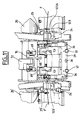
- Figures 9, 10, 11 show slightly different views of a tool according to the invention seen from the front.
- Figure 12 shows a rear view of the tool according to the invention.
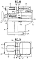
- Figures 13 and 14 show a tool clamping arrangement according to the invention on the one hand in left view and on the other hand in top view.
- Figures 15 and 16 respectively show a left view of one of the stripping arrangements for a tool according to the invention and a view of above showing in particular the two stripping arrangements of a tool according to the invention.
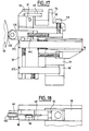
- Figures 17 and 18 show respectively a left view of one of the cleavage arrangements for a tool according to the invention and a view of above this arrangement.
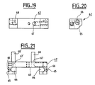
- Figures 19, 20, 21 show an example of a module holder for tool according to the invention respectively in front view, from left and from below.
- the tool according to the invention is intended for allow the connection at the end of an optical fiber either to another fiber optical, either to an optical connector element via a connection module comprising a receiver box allowing a introduction of fiber at at least one end and means for fixing fiber (s) by wedging at the bottom of the housing which are implemented by depression.
- Figures 1 to 8 show a non-limiting example of a module connection at the end, here a so-called splice module for two fibers, with its immobilizing element.
- This module comprises for this purpose a receiver box 1 intended for receive two fibers and an immobilizing element 2 intended to cooperate with the receiver box 1 to ensure the holding in position of the two fibers optics, such as F, F 'sketched in Figure 11, after they have been positioned end to end to ensure optical continuity satisfactory between these fibers.
- an immobilizing element 2 intended to cooperate with the receiver box 1 to ensure the holding in position of the two fibers optics, such as F, F 'sketched in Figure 11, after they have been positioned end to end to ensure optical continuity satisfactory between these fibers.
- the receiver box 1 is in the form of a box in molded material, such as for example a thermoplastic resin, having the appearance rectangular parallelepiped which has a longitudinal cavity opening open at one of its large faces to receive an immobilizing element part 3 2.
- the bottom of the cavity that includes the receiver box 1 has a longitudinal central groove 4 intended to receive two fibers to be connected in end provided to enter this cavity by orifices 5, arranged in opposite side walls of the housing at the bottom of the cavity and each at one end of the groove 4.
- Each orifice 5 by its very shape or possibly by the form of a tip that it receives, flares outwards from the housing to favor the entry of a fiber and at a determined diameter into that of its parts which extend towards the inside of the cavity to center suitably the end to be connected of a fiber of given diameter, the diameter of the orifices or end pieces which they possibly contain being chosen according to those of the fibers to be connected. These are planned to come into abutment against each other in the middle part of the groove longitudinal 4.
- the receiver unit 1 also comprises means intended for allow the immobilizing element 2 to be fixed on the one hand in one first position leaving a possibility of free passage to the fibers in the groove 4 between the bottom of this groove and the immobilizing element 2, on the other leaves in a second position for which the immobilizing element presses at the bottom of groove 4 any portion of fiber inserted between this groove and itself.
- These means are here transversely arranged at the ends of the housing outside of the latter and they are formed in the form of notches projecting 6, 6 'which are offset on the one hand in height, on the other hand in width in the realization presented.
- the notches 6 located on either side of the housing and at the same height are intended to allow the element to be secured immobilizer on the receiver in the first position mentioned above.
- the notches 6 'located at a lower level than the notches 6 are intended to allow the retention of the immobilizing element relative to the receiver in the second of the positions.
- each notch 6 is narrower than the notch 6 'above which it is located and relative to which it is laterally offset, as seen in Figure 2.
- the immobilizing element 2 is for example made in the same material that the receiver box 1, it includes a part 3 which is here intended to be used to apply holding pressure on the portions of fiber inserted via the orifices 5 between the groove 4 of a housing receiver 1 and itself, from the moment the immobilizing element 2 which comprises it is pushed into the second of the positions mentioned more high relative to the receiver unit 1 on which it is positioned.
- the pressing part 3 has a shape which is complementary to that of the cavity of the receiver box 1 which receives it, or here a rectangular parallelepiped shape. It is attached to a cover 7 which closes the cavity of the receiver unit 1 which it closes, when the element immobilizer 2 is in position.
- the connection between pressing part 3 and cover 7 of the same immobilizing element 2 is here assumed to be ensured by a short central pillar 8 elastically allowing a limited angular play of the part pressing relative to the cover.
- An opening 9 extends over most of the length of the pressing part 3, here near the central pillar 8, it opens laterally on either side of this pressing part. It allows the pressure exerted through the said pillar to be applied to the part pressing proper at its longitudinal ends. A optimal pressure distribution is thus obtained over the fiber portions immobilized by the pressing part at the level of the groove 4 in the housing receiver.
- the immobilizing element 2 comprises means for fixing to a receiver box 1 which are complementary to those of the latter for this purpose.
- the longitudinal ends of the cover 7 have latching tabs with notches 10, 10 'respectively intended to cooperate with the notches 6, 6 'that the receiver unit 1 comprises.
- the notches 10, 10 'oriented internally are therefore also offset on the one hand on two levels in height, on the other hand in width and the notches 10 ' which are furthest from the top of the cover 7 are also more wider than the notches 10, each having at least approximately the same width as the 6 or 6 'notches with which they are likely to be respectively brought to cooperate.
- connection to ensure the completion of the sequence of operations necessary for continuous and single connection handling after initial positioning of the fibers and the module splice on the tool.
- connection tool presented in Figure 9 is a control tool manual rotary which ensures all stripping operations partial of the fiber ends to be connected, of shaping of these ends by cleavage, insertion of the two ends of fibers to be connected at the end to their connection position in a splice module and mechanical immobilization of these ends in the module after connection so as to form a usable splice independent of the tool, after a first preliminary positioning of the fibers and a splice module on the tool.
- the rotary control is here assumed to be carried out through a member such as for example a thumb wheel 11.
- the latter is here located at one end of the tool and allows by a continuous rotation of a direction preferably not reversible determined to animate a set of means responsible for ensuring the various operations necessary for connection in one same and unique cycle.
- the wheel 11 is rotatably mounted on a tool frame 12 and drives in particular a shaft 13 carrying a plurality of actuating cams which cooperate with other functional elements of the tool in a way that is specified below, - see Figures 10 and 12 -.
- the wheel 11 actuates the shaft 13 by a return gear and a toothed wheel, as sketched in the figure 10.
- the rotational drive of the shaft 13 can be provided by a coupled electric motor and appropriately controlled according to techniques known to man business.
- Load-bearing means here constituted by two fiber-carrying trolleys 14, 14 'slide in opposite directions on either side of a central part of the frame 12 where a subset 15 of corresponding means is housed on the one hand to basic tools for preparing the ends of fibers to be connected at the end and on the other hand a sub-assembly 16 of means allowing the setting in position, maintenance and operation of a splice module as mentioned above.
- Both of these two sub-assemblies are mounted on a support cradle 17 tilting in the frame 12 and which is controlled by one of the cams so as to pass from a first position, here provided high, where the basic tools mentioned above are activated to allow the preparation of the ends of the fibers to be connected, in a second position, here planned low, where these are functional elements of the second subset mentioned above which are activated in particular to allow immobilization of the fiber ends connected at the end in a module splicing by operation of this module allowing its immobilizing element from its first to its second position.
- the cam tilting of the cradle 17 is designated by the reference 56 in FIG. 12.
- each of the two cylindrical cams 20, 20 ' are symmetrically arranged by a median transverse plane, of trace XX, from the tree 13 which carries them, they tend to symmetrically repel the two carrier carriages 14, 14 'from an initial position for which these carriages are close to the frame 12 to a position of maximum spacing said carriages in a movement parallel to the guide rods.
- Each carrying cart 14 or 14 ' is designed to receive one of the two fibers to be connected and includes a fiber holder device 123 or 123 ', mounted mobile and articulated in the carriage so that it can be partially rotate along an axis here assumed to be parallel to the guide rods.
- Each fiber holder such as 123 has a seat 123A, intended to receive a fiber and to ensure a determined positioning in the space of the longitudinal axis of a end of fiber received, and a 24 or 24 'fixing flange coming immobilize locally this fiber end by a flat part on the seat where this flange articulated at one of its ends is hooked by its other end, when it is manually maneuvered when putting in place of a fiber end for connection.
- each fiber to be connected place on the seat of the fiber holder parallel to the rods guides in a flat area of this seat which is surrounded on either side by two fiber positioning ves and which is pressed against a complementary flat part of the flange, when the latter is in position hung.
- the two positioning ves associated with a fiber holder seat are aligned and define a fiber positioning axis which is aligned with that of the other fiber holder and which extends parallel to the rods guides 18.
- Each fiber holder seat 123 or 123 ′ has a positioning arm in rotation 25 or 25 'visible in Figure 11 which is provided with a roller at a end so as to come to rest on a side projecting element 26 or 26 'oriented towards the outside of the cam 20 or 20' and to be made partially turn the fiber holder which comprises it in a vertical plane, as already indicated above.
- This partial rotation is adjustable, between 0 and around 20 °, preferably between 0 to 12 ° approximately.
- This non-zero rotation of the fiber holder allows an oblique cut of the fiber in place in the fiber holder. The zero rotation leads to a straight cut of the fiber in place.
- the sub-assembly 15 of means corresponding to tools elements for preparing the fiber ends to be connected at the east end carried by the cradle 17 tilting in the frame 12 and has an arrangement 29, said to be shared, which is fixedly mounted on the cradle and which carries five referenced arrangements of 30, 30 ', 31, 31' and 32 - see Figure 10 - mobile in translation parallel to each other under the action of flat cams referenced 33, 33 ', 34, 34' and 35 carried by the shaft 13, as seen in FIG. 12.
- the mobile arrangements 30, 30 ′ each provide a cleavage at the end of one of the different fibers to be connected in cooperation with the shared arrangement 29.
- the latter also participates, on the one hand, in the stripping partial fibers in cooperation with the arrangements 31, 31 'and, on the other hand, clamping these fibers for stripping and cleavage in cooperation with arrangement 32.
- the latter is placed in a central position between the arrangements 31 and 31 'themselves aligned with arrangements 30 and 30' which are placed at the ends of the subassembly which groups them all together. All these arrangements are mounted movable in translation transversely to the shaft 13 on the shared arrangement 29 which carries them.
- the shared arrangement 29 is provided with cylindrical guides whose orifices 36, 36 'are particularly visible on the Figures 9, 10 and 11, these holes receive guide rods 37, 37 'provided for arrangements 30, 30 ', 31, 31' and 32.
- the rods guide 37 have a circular cross section and slide in guides with complementary circular section, while the rods 37 'also with circular section slide in non-circular guides offering both precise horizontal guidance and play in the vertical direction.
- the movable clamping arrangement 32 and the complementary part of the shared arrangement 29 are presented in FIGS. 13 and 14, it comprises two horizontally movable jaws 38, 38 ', symmetrically arranged by relation to a median transverse plane of trace XX mentioned above and intended to each allow clamping against a fixed jaw 39, common, of a fibers to be connected.
- this bit 39 protrudes into an empty space formed between arrangements 29 and 32 where also the movable jaws 38, 38 'project.
- the latter are mounted on rods 40, 40 'provided with springs such as the spring 41 which allow them to come to press elastically against the fixed jaw 39, when the arrangement 32 which carries them is moved to the arrangement shared 29 by the action of cam 35.
- the arrangement 32 takes support on the profiled edge which is at the periphery of the cam 35 by via a roller 42S carried by a pusher 43S with adjusting screw 44S maintained in a housing of complementary shape where this pusher can here move in translation over a limited distance.
- the arrangement 32 slides with respect to the shared arrangement 29 and comprises two guide rods 37S, 37'S which cooperates with cylindrical guides orifices 36, 36 'of the shared arrangement 29, these guides are here constituted like those already mentioned in connection with the shared arrangement 29.
- thin rigid rods 46, 46 ' fiber release here assumed by bending two wires metallic fixed one on the shared arrangement 29 and the other on the arrangement 32, are positioned so as to intersect the path followed by a portion of fiber which may have remained pressed against one of the jaws after cleavage, when the clamping is removed by return of the movable jaws 38, 38 'to an initial position for which they are distant from the fixed jaw 39.
- the stripping arrangements 31 and 31 ', mobile, and the part complementary to the shared arrangement 29 as shown in the figures 15 and 16, have complementary stripping blades which are symmetrically arranged with respect to a median transverse plane of trace XX already mentioned above, as well as the arrangements 31 and 31 '.
- These blades of stripping referenced 47, 47 ′ when they are included by the arrangements 31, 31 'and referenced 48', 48 'when carried by the shared arrangement 29 are here assumed to be planar and on-board stripping in V shape as seen in Figure 15.
- Each roller 42D or 42'D follows the profiled edge of the cam 34 or 34 'on which it comes to bear so as to move in translation the arrangement 31 or 31 'which includes it with respect to the shared arrangement 29 so as to allow cooperation temporary stripping blades of these close arrangements for the stripping of fibers, between two periods when these arrangements are distant from same as the stripping blades they wear.
- the cleavage arrangements 30 and 30 ' are symmetrical and symmetrically situated with respect to the median transverse plane of trace XX mentioned above, each between one of the stripping arrangements 31, 31 ′ and one, different, on both sides of the cradle 17.
- Figures 17 and 18 show the respective provisions of one of them, in this case arrangement 30, and the corresponding shared arrangement part 29.
- Each cleavage arrangement includes a cutting diamond, such as diamond 49 for the cleavage arrangement 30, which it leads to the arrangement shared 29 when moved to it under the action of the cam corresponding, here 33, until it comes to cut the fiber axis defined by the corresponding fiber holder, in this case the fiber holder 123 and possibly the fiber to be connected held by this fiber holder and by the jaws, here 38 and 39, of the clamping arrangements 32 and of the complementary part of shared arrangement 29 between which this fiber is then immobilized.
- a cutting diamond such as diamond 49 for the cleavage arrangement 30, which it leads to the arrangement shared 29 when moved to it under the action of the cam corresponding, here 33, until it comes to cut the fiber axis defined by the corresponding fiber holder, in this case the fiber holder 123 and possibly the fiber to be connected held by this fiber holder and by the jaws, here 38 and 39, of the clamping arrangements 32 and of the complementary part of shared arrangement 29 between which this fiber is then immobilized.
- Each diamond is immobilized here by an immobilization piece, such 50 fixed by a screw 51 on a support 52 itself positioned with precision on the cleavage arrangement which carries it and on which it is fixed here by a screw 53. Measures are taken to limit the possibilities of contact with the free and cutting end of each diamond except for the fiber to be cleaved, such is in particular the object of the protective element 54 located in face of the cutting end of diamond 49 in FIGS. 17 and 18. It is also provided an additional protection plate 55 not shown on the figure 18 which is placed laterally with respect to the diamond on the corresponding support as seen in Figure 17.
- each diamond strike the fiber laterally held taut between the device nearest 123 or 123 'fiber holder and clamping jaws 39 and 38 or 38' located in the center of the tool to ensure the cleavage of this fiber.
- each cleavage arrangement comprises a pusher provided with a roller bearing on, such as the pusher 43C provided with a roller 42C seen in Figures 17 and 18.
- the pushers are mounted on the cleavage arrangements which comprise in a way corresponding at least approximately to those provided for pushers 43D or 43S which respectively comprise arrangements 31, 31 'and 32.
- the sub-assemblies 15 and 16 are mounted on a cradle 17 tilting in the frame 12 around the shaft 13 with respect to which this cradle rotates. Tipping of the cradle 17 are controlled by a cam 56 here located between the cam 20 'and the cradle 17 on the shaft 13 which carries them.
- a cam 56 here located between the cam 20 'and the cradle 17 on the shaft 13 which carries them.
- an arm is not provided shown articulated on the frame 12, one end of which comes to take pressing on the profile of the cam 56 by means of a roller not shown, the other end is secured to the cradle.
- the cradle 17 is mechanically held in the high position for a first part of the rotation of the cam 56 due to the edge profile of the latter to allow the preparation of fibers by tools comprised by the sub-assembly 15, before connection.
- the cradle 17 is tilted in the low position here by gravity, as soon as the profile of the cam 56 authorizes it by allowing the roller that carries the arm to approach the axis of the shaft 13 for one second part of the rotation of this cam 56.
- the passage of the position cradle 17 high in the low position under the effect of gravity is slowed down by friction a braking piece 57, integral with the frame 12, against an overthickness 58, progressively profiled, which comprises the cylindrical cam 20 to proximity to the frame, this part and this extra thickness being partially shown in Figure 12.
- the extra thickness 58 also shown in the Figure 10, is here assumed to be covered by an effect coating element non-slip promoting braking.
- Tilting the cradle to the lower position brings the positioning of the sub-assembly 16 at the fiber level as defined by fiber carriers 123 and 123 ', simultaneously with the movement towards the bottom of the sub-assembly 15 previously located at this level.
- the sub-assembly 16 essentially comprises a support element corresponding to the part referenced 16 in FIG. 9. This support element is fixed in the upper part of cradle 17 and receives a module holder preferably removable splice 60 which accommodates and positions a module connection as described above.
- module holders compatible with the support element that comprises the sub-assembly 16, these module holders being adapted to allow the use of the modules then planned, as further developed.
- the support element of the sub-assembly 16 also receives a device for pusher crimping 61 positioned above the module holder 60 when this one is in place.
- the module holder 60 includes a metal receiving part 62 presented in detail in the figures 19, 20 and 21.
- This receiving part has a longitudinal housing for receiving a splice module consisting of a receiver box 1 and an immobilizing element 2.
- This housing is here delimited by a wall smooth 63 against which the module is positioned and by two cavities 64 which each receive one module end, the latter coming to position itself precisely in these cavities where it is introduced in sliding along the smooth wall so as to abut at the bottom of these cavities.
- Two orifices 65 are symmetrically provided each at one end of a cavity so as to lead to the outside of the workpiece ends of the latter and allow accordingly the introduction a fiber each to the inside of the receiver box 1 of a module, via one of the orifices 5 of this receiver unit.
- these orifices 65 which preferably have an entry widening outwards to facilitate the introduction of fiber, are also laterally open each by a longitudinal slot 66 which leads outside in a direction opposite to that of the introduction of a module in a receiving part 62 of module holder 60.
- These slots 66 allow the passage of the two fibers connected to an assembled module when the module is dissociated from the receiving part 62, after connection of the fibers.
- the receiving part 62 is fixed against a front wall of the support element of the sub-assembly 16 so as to be removable, two conduits 67 and 67 'are provided in the receiving part 62 to receive two rods 68 and 68 'for positioning this receiving part 62 on the front wall in corresponding conduits, not shown.
- at least one of the rods 68, 68 'and one of the conduits are arranged in a manner known to those skilled in the art to ensure a snap to immobilize the removable receiving part 62 against the front wall of the support element against which it was pushed and remove it manually if necessary.
- This can in particular allow to replace the receiving part 62 mentioned above by a similar part provided for another splicing module for two fibers or for a module designed to connect a fiber to another element, for example a optical connector.
- the push button crimping device here comprises two push buttons 61 Figure 9 which are positioned above the module holder 60 on the front wall of the support element of the sub-assembly 16 and more particularly opposite longitudinal ends of an immobilizing element 2 of a module splice in place in the module holder 60 so that it can come press on these ends.
- Each of these pushers has here an element support 69 or 69 'integral with a rod which slides in a formed orifice for it in one end of a support stirrup 70, here in U as it is see in particular in FIG. 9.
- Caliper 70 is actuated by a first end of a movable arm 72 - see figures 9 to 12 - which is articulated on the support element of the sub-assembly 16 and which carries a roller 73 at its other end, this roller 73 is supported on the edge peripheral of a cam 74, here flat, carried by the shaft 13.
- the profile of the cam 74 is produced in a manner known to those skilled in the art so that the rotation of the shaft 13 at the end of the cycle successively leads to crimping fibers in the splice module due to the simultaneous support of pushers 69 and 69 'on the ends of the immobilizing element 2 of a splice module in place in the receiving part 62 of the module holder and subsequently return to the initial position of the pushers for removing the splice module connected to the two fibers connected together by its intermediate.
- connection tool is designed to allow the execution of the sequence of operations necessary for connection in a single rotation cycle of the shaft 13, by means of the wheel, allowing to animate the mobile functional elements of the tool apart from a first positioning of the fibers and the splice module on the tool.
- a splicing module in the receiving part 62 of a module holder is already in place on the connection that includes it, possibly before positioning the receiving part 62 on this tool, while the operating wheel 11 has been placed in an initial position which alone allows the start of a fiber (s) connection.
- the cradle is then in its high position to which the sub-assembly 15 is at the fiber level while the sub-assembly 16 is above.
- Each fiber is then positioned manually in the way indicated above by the operator handling the tool, this fiber passing then at the bottom of the positioning ves surrounding the seat of the fiber holder 123 or 123 'which receives it, before being immobilized by the drawdown and the attachment, here assumed manual, of the flange 24 or 24 'associated with this fiber holder.
- a fourth phase driven like the previous ones by the rotation of the shaft 13 under the action of the dial 11 controls the cleavage of each fibers by one of the cut diamonds coming laterally to strike this fiber as a result of the translational movement of the cleavage arrangement 30 or 30 'which includes it and while the fiber-carrying carriages continues to exercise tension on the fiber portions in the cleavage areas due to the profiling of the cams 20, 20 ′.
- the spacing of the carrier carriages 14, 14 'then ceases due to the profile change provided for this purpose on the cams 20, 20 'and the jaws of tightening 38, 38 'deviate from the fixed jaw 39 due to the action of the cam 35 driven by the shaft 13 with all the other cams, as before, in a fifth phase.
- the respective spacing of each jaw 38, 38 ' causes the passage of one end of one of the rods 46 or 46' at the level where is likely a portion of fiber that was previously immobilized between the fixed jaw 39 and one of the jaws 38 or 38 'and that the operation breaking has separated from the rest of the fiber of which it was part. This portion of fiber is then separated from the bit against which it was previously applied, if it had not fallen due to its weight alone, this fall then being driven by the pressing on it of a rod end 46 or 46 '.
- the continued rotation of the shaft 13 then causes the tilting of the cradle 17 in the frame 12 from its high position to its low position under the action of the cam 56. It leads to the positioning of the sub-assembly 16 at the fiber level as determined by the fiber-carrying devices 123, 123 ′, the latter tilting to their initial position by erasing the projecting elements 26, 26 ′ due to the rotation of the shaft 13 and of the cam 20, 20 '.
- the arrival of the sub-assembly 16 in the low position results in a positioning of the receiver box 1 of the splice module housed in the module holder 60 of the connection tool at a level for which the axis of the orifices 5 for introducing fiber into said housing 1 are aligned with the axis of fibers defined by the fiber-carrying devices 123, 123 '.
- the split ends of the two fibers respectively carried by these devices are therefore aligned each facing one of the two orifices 5 of the receiver unit 1.
- the profile of the cams 20 and 20 ′ is established in a manner known from the person skilled in the art so that the cleaved ends of the two fibers come apply one against the other in the receiver box 1, when the two carrier carriages 14, 14 'have returned at a determined distance from their initial position near the frame, under the action of these cams.
- the continued rotation of the shaft 13 leads the cam 74 to command a simultaneous pressing of the pushers 69 on the ends of the immobilizing element 2 of the splice module in place in the receiving part 62 of the module holder 60, by acting on the movable arm 72 of the crimping device.
- This immobilizing element 2 which was hitherto in a first position relative to the receiver unit 1 of the module which comprises them so as to allow the passage of fibers between itself and the bottom of the cavity of this receiver box 1, then comes in the second position provided for which it holds in place by pressure the ends of the fibers introduced into the cavity mentioned above via the orifices 5 formed in the ends of this cavity.
- connection tool is then ready again for a new cycle.
- the cutting of the fibers can be made straight as desired, instead of being oblique, by removing the twist applied to the fiber or fibers.
- the tool described as being a double tool can be transformed into a simple tool, by deleting one of the two parts symmetrical along the axis XX 'and conservation of the aforementioned central cam 35.
- cams will have the appropriate profiles to adjust the stripping length of the fiber (s) and tighten and the desired cleavage.
Landscapes
- Physics & Mathematics (AREA)
- General Physics & Mathematics (AREA)
- Optics & Photonics (AREA)
- Mechanical Coupling Of Light Guides (AREA)
Applications Claiming Priority (2)
| Application Number | Priority Date | Filing Date | Title |
|---|---|---|---|
| FR9616188A FR2757958B1 (fr) | 1996-12-30 | 1996-12-30 | Outil de raccordement d'une fibre a une autre fibre ou a un element de connectique optique par l'intermediaire d'un module de raccordement |
| FR9616188 | 1996-12-30 |
Publications (1)
| Publication Number | Publication Date |
|---|---|
| EP0851249A1 true EP0851249A1 (de) | 1998-07-01 |
Family
ID=9499276
Family Applications (1)
| Application Number | Title | Priority Date | Filing Date |
|---|---|---|---|
| EP97403179A Withdrawn EP0851249A1 (de) | 1996-12-30 | 1997-12-30 | Werkzeug zur Verbindung einer Faser mit einer anderen Faser oder mit einem optischen Verbindungselement mittels eines Verbindungsmoduls |
Country Status (5)
| Country | Link |
|---|---|
| US (1) | US5999682A (de) |
| EP (1) | EP0851249A1 (de) |
| JP (1) | JPH10197743A (de) |
| CA (1) | CA2223864C (de) |
| FR (1) | FR2757958B1 (de) |
Cited By (4)
| Publication number | Priority date | Publication date | Assignee | Title |
|---|---|---|---|---|
| FR2803397A1 (fr) * | 2000-01-05 | 2001-07-06 | Fci Automotive France | Outil de sertissage particulierement adapte pour les cosses terminales des guides d'ondes en fibre optique et machine a sertir associee |
| DE19842122C2 (de) * | 1998-09-05 | 2002-03-14 | Rennsteig Werkzeuge Gmbh | Zangenartig zu handhabendes Werkzeug |
| CN116854362A (zh) * | 2023-06-25 | 2023-10-10 | 华能(泰安)光电科技有限公司 | 光纤预制棒上料组件及焊接机 |
| CN120190593A (zh) * | 2025-05-12 | 2025-06-24 | 江苏伟德光电科技有限公司 | 一种光纤跳线生产的端部接头组装设备 |
Families Citing this family (15)
| Publication number | Priority date | Publication date | Assignee | Title |
|---|---|---|---|---|
| US6091875A (en) * | 1998-06-04 | 2000-07-18 | Sumitomo Electric Ligthwave Corp. | Optical fiber ribbon midspan splitter device |
| DE10113740A1 (de) * | 2001-03-21 | 2002-07-18 | Agilent Technologies Inc | Vorrichtung zum Bearbeiten einer isolierten optischen Faser |
| DE10209461A1 (de) * | 2002-03-05 | 2003-10-02 | Bernhard Schaefer Werkzeug Und | Verfahren und Vorrichtung zur Herstellung eines Lichtwellenleiterendes |
| US7234878B2 (en) * | 2003-08-11 | 2007-06-26 | 3M Innovative Properties Company | Optical fiber connecting device |
| JP4393128B2 (ja) * | 2003-08-11 | 2010-01-06 | スリーエム イノベイティブ プロパティズ カンパニー | 光ファイバ接続装置 |
| JP4874115B2 (ja) * | 2003-11-04 | 2012-02-15 | タイコ・エレクトロニクス・レイケム・ベスローテン・フェンノートシャップ・メット・ベペルクテ・アーンスプラーケレイクヘイト | 光ファイバーをスプライス・コネクターに設けるためのデバイス |
| DE102005001950A1 (de) * | 2005-01-14 | 2006-07-27 | Tyco Electronics Amp Gmbh | Schneidevorrichtung und Verfahren zum Schneiden einer Glasfaser |
| DE102006041865A1 (de) * | 2006-09-06 | 2008-03-27 | Siemens Ag | Optische Einrichtung zur Überwachung einer drehbaren Welle mit gerichteter Achse |
| US7567743B1 (en) * | 2008-04-02 | 2009-07-28 | Tyco Electronics Corporation | Field terminating method and device |
| DE202008016860U1 (de) * | 2008-12-19 | 2009-02-26 | CCS Technology, Inc., Wilmington | Anordnung zum Bearbeiten von Lichtwellenleitern |
| DE202009003964U1 (de) * | 2009-03-20 | 2009-05-20 | CCS Technology, Inc., Wilmington | Vorrichtung und Anordnung zum Trennen und Spleißen von Lichtwellenleitern |
| DE202010005766U1 (de) * | 2009-06-16 | 2010-10-28 | Weidmüller Interface GmbH & Co. KG | Werkzeug zur Verarbeitung von Lichtwellenleitern |
| FR3052874A1 (fr) * | 2016-06-17 | 2017-12-22 | Loxeol Asia Ltd | Equipement pour l'epissure des elements cylindriques |
| CN111465880B (zh) * | 2019-09-16 | 2022-01-28 | 四川灼识科技股份有限公司 | 光纤熔接机 |
| CN110666831B (zh) * | 2019-09-19 | 2021-05-18 | 东莞市本润机器人科技股份有限公司 | 一种机器人轻量化多关节模组 |
Citations (3)
| Publication number | Priority date | Publication date | Assignee | Title |
|---|---|---|---|---|
| US4416506A (en) * | 1981-07-22 | 1983-11-22 | Amp Incorporated | Apparatus for splicing fiber optic waveguides |
| FR2614142A1 (fr) * | 1987-04-15 | 1988-10-21 | Souriau & Cie | Dispositif de denudage d'un fil gaine |
| EP0509737A2 (de) * | 1991-04-12 | 1992-10-21 | The Furukawa Electric Co., Ltd. | Vorrichtung zum Bearbeiten der Spitzen von ummantelten optischen Fasern |
Family Cites Families (1)
| Publication number | Priority date | Publication date | Assignee | Title |
|---|---|---|---|---|
| US4046298A (en) * | 1975-12-29 | 1977-09-06 | Western Electric Company, Inc. | Methods and apparatus for stripping optical fiber ribbons |
-
1996
- 1996-12-30 FR FR9616188A patent/FR2757958B1/fr not_active Expired - Fee Related
-
1997
- 1997-12-26 JP JP9361290A patent/JPH10197743A/ja not_active Withdrawn
- 1997-12-29 US US08/998,840 patent/US5999682A/en not_active Expired - Fee Related
- 1997-12-29 CA CA002223864A patent/CA2223864C/fr not_active Expired - Fee Related
- 1997-12-30 EP EP97403179A patent/EP0851249A1/de not_active Withdrawn
Patent Citations (3)
| Publication number | Priority date | Publication date | Assignee | Title |
|---|---|---|---|---|
| US4416506A (en) * | 1981-07-22 | 1983-11-22 | Amp Incorporated | Apparatus for splicing fiber optic waveguides |
| FR2614142A1 (fr) * | 1987-04-15 | 1988-10-21 | Souriau & Cie | Dispositif de denudage d'un fil gaine |
| EP0509737A2 (de) * | 1991-04-12 | 1992-10-21 | The Furukawa Electric Co., Ltd. | Vorrichtung zum Bearbeiten der Spitzen von ummantelten optischen Fasern |
Cited By (5)
| Publication number | Priority date | Publication date | Assignee | Title |
|---|---|---|---|---|
| DE19842122C2 (de) * | 1998-09-05 | 2002-03-14 | Rennsteig Werkzeuge Gmbh | Zangenartig zu handhabendes Werkzeug |
| FR2803397A1 (fr) * | 2000-01-05 | 2001-07-06 | Fci Automotive France | Outil de sertissage particulierement adapte pour les cosses terminales des guides d'ondes en fibre optique et machine a sertir associee |
| EP1115015A1 (de) * | 2000-01-05 | 2001-07-11 | F.C.I. - Framatome Connectors International | Krimpwerkzeug, insbesondere für faseroptische Wellenleiter-Endgeräte und damit assoziierte Krimpgeräte |
| CN116854362A (zh) * | 2023-06-25 | 2023-10-10 | 华能(泰安)光电科技有限公司 | 光纤预制棒上料组件及焊接机 |
| CN120190593A (zh) * | 2025-05-12 | 2025-06-24 | 江苏伟德光电科技有限公司 | 一种光纤跳线生产的端部接头组装设备 |
Also Published As
| Publication number | Publication date |
|---|---|
| CA2223864C (fr) | 2002-02-12 |
| US5999682A (en) | 1999-12-07 |
| JPH10197743A (ja) | 1998-07-31 |
| FR2757958A1 (fr) | 1998-07-03 |
| FR2757958B1 (fr) | 1999-01-22 |
| CA2223864A1 (fr) | 1998-06-30 |
Similar Documents
| Publication | Publication Date | Title |
|---|---|---|
| CA2223864C (fr) | Outil de raccordement d'une fibre a une autre fibre ou a un element de connectique optique par l'intermediaire d'un module de raccordement | |
| FR2589588A1 (fr) | Appareil de polissage de fibres optiques mutiples | |
| EP0686450B1 (de) | Schneidvorrichtung für profilierte Materialien, insbesonder für Rinnen | |
| FR2648741A1 (fr) | Lame de coupe et procede de decoupage de matiere en feuille | |
| EP0255425B1 (de) | Gerät zum automatischen Auflegen einer Fasermatte auf eine Form, sowie Vorrichtungen mit einem derartigen Gerät | |
| FR2596948A1 (fr) | Appareil a ebrancher les troncs d'arbres | |
| EP0034688A2 (de) | Maschine zum Bespannen von Schlägern | |
| EP0141745B1 (de) | Automatische Maschine zum Biegen in einer räumlichen Konfiguration feiner und gerader Elemente, insbesondere Metalldrähten | |
| FR2539122A1 (fr) | Machine pour revetir une surface quelconque avec un materiau composite de fibres et de resine | |
| EP0621409A1 (de) | Befestigungseinrichtung zwischen einem Stütz- und Bewegungsteil sowie einem Werkzeug | |
| EP0040574A1 (de) | Betätigungsvorrichtung für die Handbremse | |
| EP0795504A1 (de) | Maschine zum kontinuierlichen Abwickeln von Bobinen mit zumindest einer Einrichtung zum gleichzeitigen Abwickeln von zwei paarweise oder koaxial angeordneten Bobinen | |
| FR2529871A1 (fr) | Machine pour revetir une surface quelconque avec un materiau composite de fibres et de resine | |
| FR2467612A1 (fr) | Frein de ski | |
| FR2682131A1 (fr) | Dispositif d'immobilisation en position de chargement d'un tambour a linge a chargement par le dessus. | |
| FR2541603A1 (fr) | Appareil a cintrer | |
| EP0252844B1 (de) | Automatische Vorrichtung zum Bearbeiten, insbesondere zum Schneiden von Bändern | |
| EP0082159B1 (de) | Vorrichtung zum ausrichten und einführen von drahtspeichen in löcher einer speichenradnabe | |
| EP0850722A1 (de) | Bandschleifmaschine für Innenflächen von Rotation symmetrischen Werkstücken | |
| EP0289381A2 (de) | Schreibkopf für Zeichenapparat | |
| EP0699610A1 (de) | Vorrichtung zum Schneiden und klebstofflosen Anbringen des Bahnanfangs für eine neue Wickelrolle auf den Wickelkern eines Wicklers | |
| FR2837435A1 (fr) | Organe de manoeuvre d'un dispositif de reglage pour siege de vehicule automobile | |
| EP0096608A1 (de) | Faseroptischer Kollimator, Anwendung zur Realisierung optischer Schaltervorrichtungen | |
| FR2543871A1 (fr) | Procede pour saisir des objets au moyen d'un bras de prehension et pince de prehension | |
| FR2558603A1 (fr) | Dispositif de mise en application des faces optiques d'au moins une paire de fibres optiques dans un dispositif de raccordement |
Legal Events
| Date | Code | Title | Description |
|---|---|---|---|
| PUAI | Public reference made under article 153(3) epc to a published international application that has entered the european phase |
Free format text: ORIGINAL CODE: 0009012 |
|
| AK | Designated contracting states |
Kind code of ref document: A1 Designated state(s): BE DE ES FR GB IT NL SE |
|
| RAP3 | Party data changed (applicant data changed or rights of an application transferred) |
Owner name: ALCATEL |
|
| 17P | Request for examination filed |
Effective date: 19990104 |
|
| AKX | Designation fees paid |
Free format text: BE DE ES FR GB IT NL SE |
|
| RBV | Designated contracting states (corrected) |
Designated state(s): BE DE ES FR GB IT NL SE |
|
| RAP3 | Party data changed (applicant data changed or rights of an application transferred) |
Owner name: ALCATEL |
|
| RAP1 | Party data changed (applicant data changed or rights of an application transferred) |
Owner name: NEXANS |
|
| STAA | Information on the status of an ep patent application or granted ep patent |
Free format text: STATUS: THE APPLICATION HAS BEEN WITHDRAWN |
|
| 18W | Application withdrawn |
Effective date: 20030116 |