EP0851401A2 - Videobildanzeigegerät mit einer Bildbreiteneinstellungsschaltung - Google Patents
Videobildanzeigegerät mit einer Bildbreiteneinstellungsschaltung Download PDFInfo
- Publication number
- EP0851401A2 EP0851401A2 EP97122708A EP97122708A EP0851401A2 EP 0851401 A2 EP0851401 A2 EP 0851401A2 EP 97122708 A EP97122708 A EP 97122708A EP 97122708 A EP97122708 A EP 97122708A EP 0851401 A2 EP0851401 A2 EP 0851401A2
- Authority
- EP
- European Patent Office
- Prior art keywords
- horizontal
- display
- video
- vertical
- microcomputer
- Prior art date
- Legal status (The legal status is an assumption and is not a legal conclusion. Google has not performed a legal analysis and makes no representation as to the accuracy of the status listed.)
- Withdrawn
Links
Images


Classifications
-
- G—PHYSICS
- G09—EDUCATION; CRYPTOGRAPHY; DISPLAY; ADVERTISING; SEALS
- G09G—ARRANGEMENTS OR CIRCUITS FOR CONTROL OF INDICATING DEVICES USING STATIC MEANS TO PRESENT VARIABLE INFORMATION
- G09G5/00—Control arrangements or circuits for visual indicators common to cathode-ray tube indicators and other visual indicators
- G09G5/003—Details of a display terminal, the details relating to the control arrangement of the display terminal and to the interfaces thereto
-
- G—PHYSICS
- G09—EDUCATION; CRYPTOGRAPHY; DISPLAY; ADVERTISING; SEALS
- G09G—ARRANGEMENTS OR CIRCUITS FOR CONTROL OF INDICATING DEVICES USING STATIC MEANS TO PRESENT VARIABLE INFORMATION
- G09G2320/00—Control of display operating conditions
- G09G2320/08—Arrangements within a display terminal for setting, manually or automatically, display parameters of the display terminal
Definitions
- the present invention relates to video display devices for sampling and displaying the video output signal from signal sources such as computers, and more specifically, to horizontal display width adjustment circuits and vertical display width adjustment circuits which allow the width of the display screen to be adjusted as required in spite of timing incompatibility between the input video signal and the predetermined effective screen area, and liquid crystal video display devices employing these width adjusting circuits.
- phase difference between the horizontal and vertical synchronizing signals and video signals produced from signal sources such as computers generally vary according to the signal source.
- the number of picture elements per horizontal scanning period and the number of lines per vertical scanning period of the video signal produced from the signal source also diversify.
- the display width of that signal source becomes smaller than the displayable screen area.
- the image width may become wider than the displayable screen area.
- the prior art may display the video image of the signal source at a narrower width than the displayable screen area of the video display device depending on the video output signal from the computer when video output signals from different models of computer are displayed in a one to one ratio (the ratio of the number of picture elements in the signal source to the number of display elements).
- the video image of the signal source may become wider than the displayable screen area of the video display device in the prior art depending on the video output signal from the computer when video output signals from different models of computers are displayed in a one to integer ratio (the ratio of the number of picture elements in the signal source to the number of display elements).
- the user may not be able to see part of the video image, and may need to painstakingly adjust one or both horizontal and vertical screen positions to see the missing part.
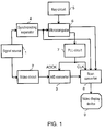
- a display width adjusting circuit of the present invention comprises a key circuit for requesting expansion and compression of horizontal and vertical display areas, a microcomputer for detecting the on and off states of the key circuit and also detecting horizontal and vertical synchronizing signal frequency of the input video signal, a PLL circuit which receives the setting for the frequency division ratio from the microcomputer, an A/D converter which receives the analog video signal and is controlled by the PLL circuit under the control of the microcomputer, and a scan converter which receives the output signal from the A/D converter, horizontal and vertical synchronizing signals, and the clock signal from the PLL circuit, and is controlled by the microcomputer for outputting the video signal which can be displayed in a required size of display image on a required area of the screen of a video display device.
- a signal source 1 outputs analog R, G, and B signals and synchronizing signals.
- a video circuit 2 amplifies the analog R, G, and B signals output from the signal source 1, and outputs amplified analog R, G, and B signals.
- An A/D converter 3 samples the analog R, G, and B signals amplified by the video circuit 2 according to a sampling signal ADCK output from a PLL circuit 7, converts them to digital R, G, and B signals by quantization, and outputs the digital R, G, and B signals.
- a synchronizing separator 4 separates and outputs the horizontal synchronizing signal and vertical synchronizing signal from the signal output from the signal source.
- a key circuit 5 adjusts the video display width and sets the position of the display screen, luminance, and contrast of the video display device by turning on and off a key switch.
- a microcomputer 6 detects the on and off states of the key switch.
- the microcomputer 6 also calculates the frequency of the horizontal and vertical synchronizing signals output from the synchronizing separator 4.
- the microcomputer 6 furthermore sets a specified frequency division ratio to a PLL circuit 7 based on the calculated frequency of horizontal and vertical synchronizing signals, and outputs the control signal for adjusting the horizontal display width according to the detected on and off states of the key switch when the key switch requests adjustment of the horizontal width of the video image to be displayed.
- the PLL circuit 7 produces and outputs the sampling signal ADCK to the A/D converter 3 and a clock signal CLK to a scan converter 8.
- the scan converter 8 is driven by the clock signal CLK output from the PLL circuit 7.
- the scan converter 8 converts the horizontal and vertical synchronizing signals output from the synchronizing separator 4 and the digital R, G, and B signals output from the A/D converter 3 to the number of picture elements displayable on a video display device 9 based on the control signal from the microcomputer 6.
- the scan converter 8 then produces the enable signal in response to the control signal from the microcomputer 6, using the clock signal CLK generated from the PLL circuit and the horizontal and vertical synchronizing signals output from the synchronizing separator 4.
- the microcomputer 6 also changes the horizontal conversion rate of the scan converter 8 which sets the horizontal display width and the phase of the enable signal which indicates the display period of the video display device 9 if there is a request to change the display condition from the key circuit 5. This allows adjustment of the horizontal display width and shifting of the horizontal display position sideways as required.
- Any request to adjust the horizontal display width can be checked at any time by repeating Steps ST101 to ST106, and the horizontal display width can be adjusted according to the new requested value.
- the microcomputer 6 counts the number of synchronizing signal pulses over a certain period to calculate the frequency of the horizontal and vertical synchronizing signals in Step ST100. It will be apparent that the microcomputer 6 can also count the time between a certain umber of synchronizing signal pulses.
- a block diagram of a second exemplary embodiment is the same as the first exemplary embodiment as shown in Fig. 1, and therefore the explanation of the configuration is omitted.
- the microcomputer outputs the control signal for adjusting the horizontal display width.
- the microcomputer 6 outputs the control signal for adjusting the vertical display width.
- the microcomputer 6 also changes the vertical conversion rate of the scan converter 8 which sets the horizontal display width and the phase of the enable signal which indicates the display period of the video display device 9 if there is a request to change the display condition from the key circuit 5. This allows adjustment of the vertical display width, shifting the display position up and down as required.
- Fig. 3 is a flow chart for a vertical display width adjustment circuit shown in Fig. 1.
- Any request to adjust the vertical display width can be checked at any time by repeating Steps ST101 to ST115, and the vertical display width can be adjusted according to the new requested value.
- the microcomputer 6 counts the number of synchronizing signal pulses over a certain period to calculate the frequency of the horizontal and vertical synchronizing signals in Step ST100. It will be apparent that the microcomputer 6 can also count the time between a certain number of synchronizing signal pulses.
- a video display device employing the horizontal display width adjustment circuit and vertical display width adjustment circuit of the present invention enables the adjustment of horizontal and vertical display widths as required.
- the present invention prevents the video output signal from a computer to be displayed in a narrower horizontal display area than that of the video display device, or contrarily, the video output signal from a computer to be displayed in a larger horizontal display area than that of the video display device which causes the occurrence of missing video image that the user cannot see.
- the present invention also prevents the video output signal from a computer to be displayed in a narrower vertical display area than that of the video display device, or contrarily, the video output signal from a computer to be displayed in a larger display area than that of the video display device which causes the occurrence of missing video image that the user cannot see.
- the video display device of the present invention also has the advantage of allowing the user to freely set the screen display width by employment of the horizontal display width and vertical display width adjustment circuits.
- the video display device of the present invention is not limited to liquid crystal video display devices. It can be applied to any display devices employing discrete display elements in a matrix. For example, the present invention is also applicable to plasma video display devices.
- the exemplary embodiments described herein are therefore illustrative and not restrictive. The scope of the invention being indicated by the appended claims and all modifications which come within the true spirit of the claims are intended to be embraced therein.
Landscapes
- Engineering & Computer Science (AREA)
- Physics & Mathematics (AREA)
- Computer Hardware Design (AREA)
- General Physics & Mathematics (AREA)
- Theoretical Computer Science (AREA)
- Liquid Crystal Display Device Control (AREA)
- Details Of Television Scanning (AREA)
- Controls And Circuits For Display Device (AREA)
- Transforming Electric Information Into Light Information (AREA)
Applications Claiming Priority (3)
| Application Number | Priority Date | Filing Date | Title |
|---|---|---|---|
| JP8357915A JPH10198309A (ja) | 1996-12-27 | 1996-12-27 | 水平振幅調整回路と垂直振幅調整回路とその両調整回路を備えた液晶表示装置 |
| JP357915/96 | 1996-12-27 | ||
| JP35791596 | 1996-12-27 |
Publications (2)
| Publication Number | Publication Date |
|---|---|
| EP0851401A2 true EP0851401A2 (de) | 1998-07-01 |
| EP0851401A3 EP0851401A3 (de) | 1999-09-22 |
Family
ID=18456599
Family Applications (1)
| Application Number | Title | Priority Date | Filing Date |
|---|---|---|---|
| EP97122708A Withdrawn EP0851401A3 (de) | 1996-12-27 | 1997-12-23 | Videobildanzeigegerät mit einer Bildbreiteneinstellungsschaltung |
Country Status (3)
| Country | Link |
|---|---|
| US (1) | US6181330B1 (de) |
| EP (1) | EP0851401A3 (de) |
| JP (1) | JPH10198309A (de) |
Cited By (5)
| Publication number | Priority date | Publication date | Assignee | Title |
|---|---|---|---|---|
| EP0978818A1 (de) * | 1998-08-05 | 2000-02-09 | Matsushita Electric Industrial Co., Ltd. | Schaltung zur automatischen Bildpositionsanpassung und Anzeigeeinrichtung die diese Schaltung benutzt |
| US6181330B1 (en) | 1996-12-27 | 2001-01-30 | Matsushita Electric Industrial Co., Ltd. | Width adjustment circuit and video image display device employing thereof |
| US6741906B2 (en) | 2000-02-18 | 2004-05-25 | Carl-Zeiss-Stiftung | Control unit for a machine tool or a coordinate measuring apparatus |
| US8581855B2 (en) | 2008-08-15 | 2013-11-12 | Hexagon Metrology, Inc. | Jogbox for a coordinate measuring machine |
| CN105632430A (zh) * | 2013-10-16 | 2016-06-01 | 精工爱普生株式会社 | 显示控制装置及方法、半导体集成电路装置以及显示装置 |
Families Citing this family (5)
| Publication number | Priority date | Publication date | Assignee | Title |
|---|---|---|---|---|
| JP4568923B2 (ja) * | 1999-04-19 | 2010-10-27 | ソニー株式会社 | 画像表示装置および画像信号変換装置 |
| US6300935B1 (en) * | 1999-04-20 | 2001-10-09 | Agilent Technologies, Inc. | Image interpolation circuit architecture and method for fast bi-cubic interpolation of image information |
| KR100320461B1 (ko) * | 1999-08-13 | 2002-01-12 | 구자홍 | 모니터의 동기신호 처리장치 및 방법 |
| US7486283B1 (en) * | 1999-11-18 | 2009-02-03 | Trident Microsystems (Far East) Ltd. | Method and apparatus for communicating digital data from a computer system to a display device |
| JP2002221954A (ja) * | 2001-01-29 | 2002-08-09 | Hitachi Ltd | 液晶表示装置 |
Citations (2)
| Publication number | Priority date | Publication date | Assignee | Title |
|---|---|---|---|---|
| WO1995008132A1 (en) | 1993-09-17 | 1995-03-23 | Proxima Corporation | Compact projection illumination system and method of using same |
| EP1010164A1 (de) | 1996-09-03 | 2000-06-21 | Allus Technology Corporation | Elektronisches kontrollsystem für flachbildanzeigen |
Family Cites Families (14)
| Publication number | Priority date | Publication date | Assignee | Title |
|---|---|---|---|---|
| JP2526558B2 (ja) | 1986-10-21 | 1996-08-21 | ソニー株式会社 | ビデオ信号のスキャンコンバ−タ装置 |
| JP2913797B2 (ja) | 1990-08-10 | 1999-06-28 | ソニー株式会社 | 画像拡縮処理方法 |
| US5095280A (en) | 1990-11-26 | 1992-03-10 | Integrated Circuit Systems, Inc. | Dual dot clock signal generator |
| US5841430A (en) * | 1992-01-30 | 1998-11-24 | Icl Personal Systems Oy | Digital video display having analog interface with clock and video signals synchronized to reduce image flicker |
| US5473382A (en) | 1992-11-04 | 1995-12-05 | Hitachi, Ltd. | Video signal converting apparatus for converting an interlace video signal into a non-interlace video signal for reduction |
| JP2531426B2 (ja) * | 1993-02-01 | 1996-09-04 | 日本電気株式会社 | マルチスキャン型液晶ディスプレイ装置 |
| JPH08234701A (ja) * | 1995-02-28 | 1996-09-13 | Sony Corp | 映像表示装置 |
| JPH09114443A (ja) * | 1995-10-20 | 1997-05-02 | Seiko Epson Corp | 映像スケーリング装置 |
| JPH09127902A (ja) * | 1995-11-02 | 1997-05-16 | Sony Corp | 電子機器 |
| JP3259627B2 (ja) | 1996-03-06 | 2002-02-25 | 松下電器産業株式会社 | 走査線変換装置 |
| JP3803414B2 (ja) | 1996-03-07 | 2006-08-02 | 松下電器産業株式会社 | 水平画素数変換回路 |
| EP0794525B1 (de) | 1996-03-06 | 2003-07-23 | Matsushita Electric Industrial Co., Ltd. | Bildelementumwandlungsgerät |
| US5990858A (en) * | 1996-09-04 | 1999-11-23 | Bloomberg L.P. | Flat panel display terminal for receiving multi-frequency and multi-protocol video signals |
| JPH10198309A (ja) | 1996-12-27 | 1998-07-31 | Matsushita Electric Ind Co Ltd | 水平振幅調整回路と垂直振幅調整回路とその両調整回路を備えた液晶表示装置 |
-
1996
- 1996-12-27 JP JP8357915A patent/JPH10198309A/ja active Pending
-
1997
- 1997-12-23 EP EP97122708A patent/EP0851401A3/de not_active Withdrawn
- 1997-12-26 US US08/998,445 patent/US6181330B1/en not_active Expired - Lifetime
Patent Citations (2)
| Publication number | Priority date | Publication date | Assignee | Title |
|---|---|---|---|---|
| WO1995008132A1 (en) | 1993-09-17 | 1995-03-23 | Proxima Corporation | Compact projection illumination system and method of using same |
| EP1010164A1 (de) | 1996-09-03 | 2000-06-21 | Allus Technology Corporation | Elektronisches kontrollsystem für flachbildanzeigen |
Cited By (6)
| Publication number | Priority date | Publication date | Assignee | Title |
|---|---|---|---|---|
| US6181330B1 (en) | 1996-12-27 | 2001-01-30 | Matsushita Electric Industrial Co., Ltd. | Width adjustment circuit and video image display device employing thereof |
| EP0978818A1 (de) * | 1998-08-05 | 2000-02-09 | Matsushita Electric Industrial Co., Ltd. | Schaltung zur automatischen Bildpositionsanpassung und Anzeigeeinrichtung die diese Schaltung benutzt |
| US6421092B1 (en) | 1998-08-05 | 2002-07-16 | Matsushita Electric Industrial Co., Ltd. | Automatic picture display position adjusting circuit and picture display apparatus using the same |
| US6741906B2 (en) | 2000-02-18 | 2004-05-25 | Carl-Zeiss-Stiftung | Control unit for a machine tool or a coordinate measuring apparatus |
| US8581855B2 (en) | 2008-08-15 | 2013-11-12 | Hexagon Metrology, Inc. | Jogbox for a coordinate measuring machine |
| CN105632430A (zh) * | 2013-10-16 | 2016-06-01 | 精工爱普生株式会社 | 显示控制装置及方法、半导体集成电路装置以及显示装置 |
Also Published As
| Publication number | Publication date |
|---|---|
| US6181330B1 (en) | 2001-01-30 |
| EP0851401A3 (de) | 1999-09-22 |
| JPH10198309A (ja) | 1998-07-31 |
Similar Documents
| Publication | Publication Date | Title |
|---|---|---|
| EP1783729B1 (de) | Bildanzeigevorrichtung und Treiberschaltung mit Einstellung der Auflösung | |
| US5818416A (en) | Image size adjusting apparatus for a digital display monitor | |
| EP0851401A2 (de) | Videobildanzeigegerät mit einer Bildbreiteneinstellungsschaltung | |
| US20100201874A1 (en) | Image display apparatus and method of adjusting clock phase | |
| KR100249228B1 (ko) | 디지탈 티브이의 화면비 변환장치 | |
| US8797457B2 (en) | Apparatus and method for frame rate preserving re-sampling or re-formatting of a video stream | |
| US7142252B2 (en) | Image processing apparatus and method for displaying picture-in-picture with frame rate conversion | |
| KR100596586B1 (ko) | 액정 디스플레이 장치의 화면상태 자동조정장치 및 그 방법 | |
| JPH09127903A (ja) | 電子機器 | |
| KR100648119B1 (ko) | 인터페이스 장치 및 동기 조정 방법 | |
| KR100359816B1 (ko) | 포맷 변환 장치 | |
| WO1998052183A1 (en) | Device and method for converting scanning | |
| JP4141208B2 (ja) | 映像信号処理装置、および集積回路 | |
| US7834866B2 (en) | Display panel driver and display panel driving method | |
| JP3474120B2 (ja) | スキャンコンバータ及びスキャンコンバート方法 | |
| JP2004144842A (ja) | マトリクス型ディスプレイ装置およびマトリクス型ディスプレイ装置におけるサンプリングクロック自動調整方法 | |
| JP2007221296A (ja) | 映像出力装置およびこれを備えるデジタルカメラ | |
| KR100556384B1 (ko) | 영상기기의 잔상 방지 장치 및 방법 | |
| JPH0537880A (ja) | 歪み補正回路 | |
| KR100516066B1 (ko) | 액정 표시 장치의 디스플레이 모드 자동 설정 방법 | |
| JP4114630B2 (ja) | 映像信号処理装置 | |
| JP2000056729A (ja) | 自動表示幅調整回路 | |
| KR0149294B1 (ko) | 디지탈 엔코더와 프레임 버퍼간의 영상제어신호 출력장치 | |
| KR100265705B1 (ko) | 영상 자동 조절 기능을 구비한 평판 디스플레이 장치 및 그의제어 방법 | |
| US5999993A (en) | Data transfer system having function of preventing error caused by suspension of data transfer to immediately service transfer interrupted request |
Legal Events
| Date | Code | Title | Description |
|---|---|---|---|
| PUAI | Public reference made under article 153(3) epc to a published international application that has entered the european phase |
Free format text: ORIGINAL CODE: 0009012 |
|
| AK | Designated contracting states |
Kind code of ref document: A2 Designated state(s): DE FR GB |
|
| AX | Request for extension of the european patent |
Free format text: AL;LT;LV;MK;RO;SI |
|
| PUAL | Search report despatched |
Free format text: ORIGINAL CODE: 0009013 |
|
| AK | Designated contracting states |
Kind code of ref document: A3 Designated state(s): AT BE CH DE DK ES FI FR GB GR IE IT LI LU MC NL PT SE |
|
| AX | Request for extension of the european patent |
Free format text: AL;LT;LV;MK;RO;SI |
|
| 17P | Request for examination filed |
Effective date: 19991222 |
|
| AKX | Designation fees paid |
Free format text: DE FR GB |
|
| 17Q | First examination report despatched |
Effective date: 20080715 |
|
| RAP1 | Party data changed (applicant data changed or rights of an application transferred) |
Owner name: PANASONIC CORPORATION |
|
| STAA | Information on the status of an ep patent application or granted ep patent |
Free format text: STATUS: THE APPLICATION IS DEEMED TO BE WITHDRAWN |
|
| 18D | Application deemed to be withdrawn |
Effective date: 20130702 |