EP0851446A2 - Aluminiumelektrodenfolie für elektrolytischen Kondensator und elektrolytischer Kondensator unter Verwendung dieser Folie - Google Patents
Aluminiumelektrodenfolie für elektrolytischen Kondensator und elektrolytischer Kondensator unter Verwendung dieser Folie Download PDFInfo
- Publication number
- EP0851446A2 EP0851446A2 EP97122756A EP97122756A EP0851446A2 EP 0851446 A2 EP0851446 A2 EP 0851446A2 EP 97122756 A EP97122756 A EP 97122756A EP 97122756 A EP97122756 A EP 97122756A EP 0851446 A2 EP0851446 A2 EP 0851446A2
- Authority
- EP
- European Patent Office
- Prior art keywords
- sponge
- aluminum
- etching layer
- reduction
- foil
- Prior art date
- Legal status (The legal status is an assumption and is not a legal conclusion. Google has not performed a legal analysis and makes no representation as to the accuracy of the status listed.)
- Granted
Links
Images



Classifications
-
- H—ELECTRICITY
- H01—ELECTRIC ELEMENTS
- H01G—CAPACITORS; CAPACITORS, RECTIFIERS, DETECTORS, SWITCHING DEVICES, LIGHT-SENSITIVE OR TEMPERATURE-SENSITIVE DEVICES OF THE ELECTROLYTIC TYPE
- H01G9/00—Electrolytic capacitors, rectifiers, detectors, switching devices, light-sensitive or temperature-sensitive devices; Processes of their manufacture
- H01G9/004—Details
- H01G9/04—Electrodes or formation of dielectric layers thereon
-
- H—ELECTRICITY
- H01—ELECTRIC ELEMENTS
- H01G—CAPACITORS; CAPACITORS, RECTIFIERS, DETECTORS, SWITCHING DEVICES, LIGHT-SENSITIVE OR TEMPERATURE-SENSITIVE DEVICES OF THE ELECTROLYTIC TYPE
- H01G9/00—Electrolytic capacitors, rectifiers, detectors, switching devices, light-sensitive or temperature-sensitive devices; Processes of their manufacture
- H01G9/004—Details
- H01G9/04—Electrodes or formation of dielectric layers thereon
- H01G9/048—Electrodes or formation of dielectric layers thereon characterised by their structure
- H01G9/055—Etched foil electrodes
Definitions
- This invention relates to an aluminum electrode foil for an electrolytic capacitor and an electrolytic capacitor using the foil.
- An aluminum foil conventionally used as an electrode material for aluminum electrolytic capacitors are treated by electrochemical or chemical etching in general to enlarge its effective area and increase the capacitance per unit area.
- various treatments such as removal of a surface layer of the aluminum foil, formation of an oxide film, annealing and so forth are carried out in most cases before the etching treatment.
- the applicant of the present invention has previously proposed a method of producing an aluminum electrode foil for an electrolytic capacitor, comprising steps of reducing an aluminum foil after etching the foil (Japanese Patent Laid-Open No. Hei. 6-204094) as a method capable of improving the strength of the foil without increasing the thickness while ensuring the increase of the capacitance.
- reduction of the etched foil can accomplish both increase of the capacitance per unit volume and improvement of the strength of the foil.
- the present invention has been completed on the basis of the findings described above and objects are to improve strength of an aluminum electrode foil for an electrostatic capacitor and to increase the capacitance per unit volume.
- Another object of the present invention is to provide an aluminum electrode foil for an electrolytic capacitor that can securely accomplish improvement of the strength and increase of the capacitance.
- the objects of the present invention described above can be accomplished by an aluminum electrode foil for an electrolytic capacitor having a sponge-like etching layer on at least one of the surfaces thereof, wherein the sponge-like etching layer is reduced in a direction of thickness, and aluminum density of the reduced sponge-like etching layer d2' is set from 0.8 to 2.2 g/cm 3 .
- the objects of the invention can also be accomplished by an electrolytic capacitor using the above aluminum foil as an electrode material.
- the aluminum foil used as an electrode foil preferably has high purity of at least 99.9 %, but it is not particularly limited thereto. It may have enough purity to be used for the electrode of electrolytic capacitors.
- the aluminum foil should have finished a foil rolling process and was subjected to final annealing, if required.
- the thickness is 200 ⁇ m or below, preferably from 15 to 120 ⁇ m.
- the sponge-like etching layer described above can be obtained by etching the aluminum foil.
- the term sponge-like etching layer ' represents an etching structure layer 2 having void portions 2a complicatedly communicating with one another in a generally continuous babble form in a three-dimensional direction as shown in Fig. 1B. All of the existing void portions do not have to communicate with one another completely, in other words, the etching structure layer 2 may contain independent void portions in the non communication state.
- a tunnel etching type in which pits are formed substantially perpendicular to the direction of thickness of the foil, length of a tunnel-like pit becomes shorter when the foil is reduced and the volume drops corresponding to the draft. Consequently, the effect of reduction cannot be observed.
- sponge-like etching a decrease of surface areas of void portions becomes smaller than a decrease of the volume of the most void portions. Therefore, the effect of reduction can be obtained.
- the sponge-like etching layer 2 described above may be formed on at least one of the surfaces of the aluminum foil, but it is generally formed on both surfaces of the aluminum foil.
- This sponge-like etching layer 2 is formed by etching the aluminum foil, appropriately combining various etching conditions such as composition of a treating solution, a solution temperature, treatment time and so forth.
- etching conditions such as composition of a treating solution, a solution temperature, treatment time and so forth.
- An example of the etching conditions enabling to form the sponge-like etching layer 2 will be described below.
- the etching treatment may be either electrochemical etching by applying a voltage or chemical etching without applying voltage.
- the treating solution may be a mixed solution of HCl, HNO 3 and H 3 PO 4 , a mixed solution of HCl, HNO 3 and H 2 SO 4 , a mixed solution of HCl, HNO 3 , H 3 PO 4 and H 2 SO 4 , a mixed solution of HCl, HNO 3 , H 3 PO 4 , H 2 SO 4 and AlCl 3 , a mixed solution of HCl and H 2 SO 4 , an aqueous HCl solution or the like.
- the liquid temperature is preferably from about 30 to about 85 °C.
- the treatment time will change depending on the relation to the other etching conditions, but in general it preferably takes from about 1 to about 20 minutes.
- the impressed voltage is preferably A.C., superimposed alternating current to direct current or a pulse.
- the current density is preferably set from 3 to 30 A/dm 2 .
- the etching treatment may be single stage etching in which the etching treatment is conducted once, or two or more stage etching in which the etching treatment is sequentially carried out at least twice, changing the etching conditions.
- etching performance such as removal of a surface layer, formation of an oxide film, annealing, etc.
- treatments for improving the etching performance such as removal of a surface layer, formation of an oxide film, annealing, etc., can be carried out before the etching treatment.
- the sponge-like etching layer 2 must be reduced in the direction of the thickness. This is because the strength can be improved by reducing the etching layer 2 without lowering the capacitance of the foil too much.
- the capacitance of the foil does not drop while the etching layer 2 is thinned. It means that the capacitance of the foil per unit volume increases corresponding to a decrease of thickness of the etching layer 2 . In other words, a thin, high performance and strong electrode foil can be obtained. If aluminum density of the etching layer 2 after reduction is less than 0.8 g/cm 3 , the capacitance of the foil per unit volume increases to a certain extent. However, a sufficient effect of improving the strength cannot be obtained, because a large number of voids yet exist.
- the aluminum density of the etching layer 2 after reduction exceeds 2.2 g/cm 3 , the strength of the foil can be improved.
- the effective void portions contributing to improvement of a surface expansion ratio decrease, the capacitance of the foil diminishes, and the capacitance per unit volume of the foil drops off. Therefore, the aluminum density of the etching layer 2 after reduction have to be within the range of 0.8 to 2.2 g/cm 3 .
- the aluminum density is 1.0 g/cm 3 or over and 1.8 g/cm 3 or less, and more preferably, 1.2 g/cm 3 or over and 1.5 g/cm 3 or less.
- Aluminum density of the etching layer 2 after reduction can be calculated from the equation (W1 - W2)/V1 , where W1 is weight of the aluminum foil, W2 is calculated weight of a core layer 3 shown in Fig. 1A exclusive of the etching layer 2 , and V1 is a volume of the etching layer.
- the aluminum density at the time of reckoning the calculated weight W2 is 2.7 g/cm 3 .
- Reduction of the sponge-like etching layer 2 may be carried out by a plate press or the like, but rolling an aluminum foil after etching is generally preferable. Further, it is desirable to roll an aluminum foil continuously while unwinding the coiled aluminum foil, from the aspect of production efficiency or because reduction can be carried out at constant pressure without variation. More concretely, conventional post treatments such as surface washing, drying, etc. are preferably carried out after etching the aluminum foil, and then the foil is rolled. Rolling is preferably carried out without using rolling oil (lubricant), because, if the void portions of the etching layer are filled with the rolling oil, the capacitance drops and removal of the oil is difficult.
- rolling oil lubricant
- the conditions of the reduction vary with the degrees of etching. In slight etching, the draft may be low. On the contrary, in excessive etching, the draft becomes high.
- the overall draft is selected within the range of 5 to 50 %, for example. It is preferable that only the etching layer is substantially reduced, but the core portion exclusive of the etching layer is left intact. When the aluminum foil is reduced to the extent of the core portion, the etching layer is reduced too much, so that the void portions get clogged and both of the capacitance and the strength drop.
- the aluminum density dl' is preferably set at 1.0 g/cm 3 or below.
- the capacitance does not increase, because the number of voids formed by etching is small. Therefore, even if reduction is carried out so that the aluminum density of the etching layer after reduction d2' becomes from 0.8 to 2.2 g/cm 3 , the reduction cannot be raised and an effect in improving strength may be weak.
- the aluminum density d1' is 0.9 g/cm 3 or less.
- the aluminum density of the etching layer before reduction d1' is less than 0.6 g/cm 3 , the number of ineffective voids is so great that the capacitance per unit volume after reduction of the etching layer cannot be much increased. Therefore, the aluminum density before reduction d1' is set at least 0.6 g/cm 3 , and more preferably, from 0.7 to 0.9 g/cm 3 .
- the ratio d2/d1' of the aluminum density of the sponge-like layer after reduction d2' to that of the layer before reduction d1' is preferably from 1.2 to 3.7. If the ratio d2/d1' is less than 1.2, reduction is sometimes insufficient and the effect in improving strength is low even though the aluminum density of the sponge-like etching layer before reduction is 1.0 g/cm 3 or less. On the other hand, if the ratio d2/d1' exceeds 3.7, reduction becomes excessive, so that the voids decrease or the void portions get clogged, the overall capacitance drops and eventually, the effect of increasing the capacitance per unit volume cannot be obtained in some cases. From the aspects of both strength and capacitance, more preferably, the ratio d2/d1' is from 1.3 to 2.7.
- the aluminum foil in which the aluminum density of the etching layer 2 after reduction d2' is set from 0.8 to 2.2 g/cm 3 may be annealed, as occasion required, at a temperature from 200 to 500 °C in order to improve the elongation. Particularly when vacuum annealing is conducted, fine pores clogged partially due to rolling are ruptured and opened again. Weak etching may be carried out after rolling to remove the clogged portions which thinly covered fine pores in part.
- the aluminum foil described above may be used for the cathodized electrode foil for the electrolytic capacitor in its intact form, or may be used for the anodized electrode foil after carrying out anodic oxidation in a solution or an aqueous solution of boric acid, ammonium borate, ammonium adipate, ammonium tartrate or the like to form an oxide film.
- the sponge-like etching layer is formed on at least one of the surfaces of the aluminum foil, the sponge-like etching layer is reduced in the direction of thickness, and the aluminum density of the reduced sponge-like etching layer d2' is controlled to the range from 0.8 to 2.2 g/cm 3 . Therefore, in comparison with conventional etched foils without reduction, improvement of the strength and increase of the capacitance per unit volume can be accomplished by the present invention more reliably and stably. Moreover, because draft is not need of control during the production and aluminum density of the sponge-like etching layer of finished products may only be controlled, control of various aluminum electrode foils becomes extremely easy.
- the aluminum density of the sponge-like etching layer before reduction d1' is 1.0 g/cm 3 and less, or when the ratio d2/d1' of the aluminum density of the sponge-like layer after reduction d2' to that of the layer before reduction d1' is from 1.2 to 3.7, improvement of the strength and increase of the capacitance per unit volume can be obtained more reliably and stably, and the control becomes further easier.
- the aluminum electrolytic capacitor using the aluminum foil described above as the electrode material can be increased the capacitance when the capacitor is set at the same size as a conventional electrolytic capacitor, and the size can be diminished when the capacitance is set at the same value as a conventional capacitor.
- a plurality of coiled aluminum foils having purity of 99.98 % and thickness of 108 ⁇ m were annealed at 300 °C for 6 hours in the N 2 gas atmosphere.
- the aluminum density of each etching layer after rolling d2' was measured and the ratio of aluminum density of the etching layer before reduction to that of the layer after reduction d2/d1' was calculated.
- the results are shown in Table 2.
- the aluminum density of the etching layer d1' and d2' were determined by the equation (W1 - W2)/V1 , where W1 is the weight of the aluminum foil, W2 is the calculated weight of the core layer and V1 is the volume of the etching layer.
- Each aluminum foil is produced under the above conditions. Then, the tensile strength was measured before and after reduction and the capacitance of each of the aluminum foil before and after reduction was determined after formation in an ammonium adipate bath with 20 V. Table 2 shows the relative ratio of the capacitance per unit volume calculated from the capacitance of the aluminum foils before and after reduction, and the draft.
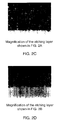
- Figs. 2A to 2D are photographs of the sections of the sample of Embodiment No. 7 before and after reduction, and Figs. 3A and 3B show secondary electron images of the surface of the etching layer before and after reduction, respectively.
- kind of etching bath composition liquid temperature (°C) condition of electrolysis treatment time (minute) A 7%HCl+0.6%HNO 3 +0.1%H 2 S0 4 35 AC50Hz, 15A/dm 2 14 B 5%HCl+0.3%H 3 PO 4 +0.1%HNO 3 50 AC60Hz, 15A/dm 2 18 C same as A 35 AC50Hz, 15A/dm 2 10 D same as B 50 AC60Hz, 15A/dm 2 16 E same as A 35 AC50Hz, 15A/dm 2 16 F same as A 35 AC50Hz, 15A/dm 2 12
Landscapes
- Engineering & Computer Science (AREA)
- Power Engineering (AREA)
- Microelectronics & Electronic Packaging (AREA)
- Fixed Capacitors And Capacitor Manufacturing Machines (AREA)
- ing And Chemical Polishing (AREA)
Applications Claiming Priority (3)
| Application Number | Priority Date | Filing Date | Title |
|---|---|---|---|
| JP35989896A JP3258249B2 (ja) | 1996-12-25 | 1996-12-25 | 電解コンデンサ用アルミニウム電極箔 |
| JP35989896 | 1996-12-25 | ||
| JP359898/96 | 1996-12-25 |
Publications (3)
| Publication Number | Publication Date |
|---|---|
| EP0851446A2 true EP0851446A2 (de) | 1998-07-01 |
| EP0851446A3 EP0851446A3 (de) | 1999-12-22 |
| EP0851446B1 EP0851446B1 (de) | 2004-04-28 |
Family
ID=18466860
Family Applications (1)
| Application Number | Title | Priority Date | Filing Date |
|---|---|---|---|
| EP97122756A Expired - Lifetime EP0851446B1 (de) | 1996-12-25 | 1997-12-23 | Verfahren zur Herstellung einer Aluminiumelektrodenfolie für Elektrolytkondensatoren und eines Elektrolytkondensators unter Verwendung dieser Folie |
Country Status (9)
| Country | Link |
|---|---|
| US (1) | US6038124A (de) |
| EP (1) | EP0851446B1 (de) |
| JP (1) | JP3258249B2 (de) |
| KR (1) | KR100403245B1 (de) |
| CN (1) | CN1132205C (de) |
| DE (1) | DE69728847T2 (de) |
| MY (1) | MY123115A (de) |
| SG (1) | SG65713A1 (de) |
| TW (1) | TW353187B (de) |
Cited By (8)
| Publication number | Priority date | Publication date | Assignee | Title |
|---|---|---|---|---|
| WO2000019470A1 (en) * | 1998-09-30 | 2000-04-06 | Cardiac Pacemakers, Inc. | High-energy electrolytic capacitors for implantable defibrillators |
| US6187028B1 (en) | 1998-04-23 | 2001-02-13 | Intermedics Inc. | Capacitors having metallized film with tapered thickness |
| US6249423B1 (en) | 1998-04-21 | 2001-06-19 | Cardiac Pacemakers, Inc. | Electrolytic capacitor and multi-anodic attachment |
| US6275729B1 (en) | 1998-10-02 | 2001-08-14 | Cardiac Pacemakers, Inc. | Smaller electrolytic capacitors for implantable defibrillators |
| US6385490B1 (en) | 1999-12-16 | 2002-05-07 | Cardiac Pacemakers, Inc. | Capacitors with recessed rivets allow smaller implantable defibrillators |
| US6421226B1 (en) | 1998-10-02 | 2002-07-16 | Cardiac Pacemakes, Inc. | High-energy capacitors for implantable defibrillators |
| US6426864B1 (en) | 2000-06-29 | 2002-07-30 | Cardiac Pacemakers, Inc. | High energy capacitors for implantable defibrillators |
| EP2264728A1 (de) * | 2009-06-16 | 2010-12-22 | Biotronik CRM Patent AG | Verfahren zur Herstellung einer Aluminiumkernanode |
Families Citing this family (24)
| Publication number | Priority date | Publication date | Assignee | Title |
|---|---|---|---|---|
| JPH1126320A (ja) * | 1997-07-02 | 1999-01-29 | Matsushita Electric Ind Co Ltd | アルミニウム電解コンデンサ用電極箔およびアルミニウム電解コンデンサ |
| JP2002198265A (ja) * | 2000-12-26 | 2002-07-12 | Matsushita Electric Ind Co Ltd | 電解コンデンサ用電極箔の製造方法およびこれを用いた電解コンデンサ |
| JP4543580B2 (ja) * | 2000-12-26 | 2010-09-15 | パナソニック株式会社 | 積層型アルミ固体電解コンデンサの製造方法 |
| US6475368B2 (en) * | 2001-03-07 | 2002-11-05 | Kemet Electronics Corporation | Method of aqueous anodizing aluminum substrates of solid capacitors |
| US7054140B2 (en) * | 2001-05-31 | 2006-05-30 | Nippon Chemi-Con Corp. | Electrolytic capacitor and electrode foil used for electrolytic capacitor |
| JP2003109865A (ja) * | 2001-09-28 | 2003-04-11 | Nippon Chemicon Corp | 固体電解コンデンサ |
| JP2003109866A (ja) * | 2001-09-28 | 2003-04-11 | Nippon Chemicon Corp | 固体電解コンデンサ |
| TWI284335B (en) * | 2002-07-10 | 2007-07-21 | Matsushita Electric Industrial Co Ltd | Anode member for solid electrolytic condenser and solid electrolytic condenser using the anode member |
| US20040140221A1 (en) * | 2003-01-21 | 2004-07-22 | Kinard John Tony | Method of anodizing aluminum utilizing stabilized silicate solutions |
| EP2009653A4 (de) | 2006-03-31 | 2015-08-12 | Nippon Chemicon | Elektrodenmaterial für einen elektrolytkondensator |
| JP4893183B2 (ja) * | 2006-09-20 | 2012-03-07 | 日本軽金属株式会社 | 電解コンデンサ用アルミニウム電極板 |
| CN100570017C (zh) * | 2006-09-25 | 2009-12-16 | 江苏中联科技集团有限公司 | 枝杈孔铝阳极箔的扩面侵蚀方法 |
| WO2009063532A1 (ja) * | 2007-11-14 | 2009-05-22 | Nippon Light Metal Company, Ltd. | 電解コンデンサ用アルミニウムエッチド板 |
| JP6154800B2 (ja) * | 2012-02-28 | 2017-06-28 | 株式会社Uacj | 集電体用アルミニウム箔及びその製造方法 |
| KR20170018342A (ko) | 2014-06-06 | 2017-02-17 | 가부시키가이샤 유에이씨제이 | 집전체용 금속박, 집전체 및 집전체용 금속박의 제조 방법 |
| EP3489976B1 (de) * | 2016-09-16 | 2023-04-12 | Japan Capacitor Industrial Co., Ltd. | Dreidimensionale struktur |
| JPWO2018051520A1 (ja) * | 2016-09-16 | 2019-07-11 | 日本蓄電器工業株式会社 | 電解コンデンサ用電極部材および電解コンデンサ |
| JP1595451S (de) * | 2017-06-20 | 2018-01-22 | ||
| JP7028481B2 (ja) * | 2020-12-28 | 2022-03-02 | 日本蓄電器工業株式会社 | 電解コンデンサ用電極部材および電解コンデンサ |
| WO2023008558A1 (ja) * | 2021-07-30 | 2023-02-02 | パナソニックIpマネジメント株式会社 | 電解コンデンサ用電極箔、電解コンデンサ、および電解コンデンサ用電極箔の製造方法 |
| CN114188160B (zh) * | 2021-11-10 | 2025-05-30 | 乳源瑶族自治县东阳光化成箔有限公司 | 一种用于低压化成箔的电极结构材料及其应用 |
| US20260106086A1 (en) * | 2022-09-30 | 2026-04-16 | Panasonic Intellectual Property Management Co., Ltd. | Electrode foil for electrolytic capacitor, electrolytic capacitor, and production method for electrode foil for electrolytic capacitor |
| CN120660161A (zh) * | 2023-01-30 | 2025-09-16 | 松下知识产权经营株式会社 | 电解电容器用电极箔、电解电容器以及电解电容器用电极箔的制造方法 |
| JPWO2024190596A1 (de) * | 2023-03-10 | 2024-09-19 |
Family Cites Families (10)
| Publication number | Priority date | Publication date | Assignee | Title |
|---|---|---|---|---|
| US2079516A (en) * | 1935-03-01 | 1937-05-04 | Magnavox Co | Aluminum electrode and method of preparing |
| NL7410690A (nl) * | 1974-01-25 | 1975-07-29 | Siemens Ag | Gelegeerde aluminiumfoelie voor hoogvolt-elec- trolytcondensatoren. |
| US4276129A (en) * | 1980-06-25 | 1981-06-30 | Matsushita Electric Industrial Co., Ltd. | Method for producing foil electrodes for electrolytic capacitor |
| JPS581046A (ja) * | 1981-06-04 | 1983-01-06 | Sumitomo Light Metal Ind Ltd | 電解コンデンサ用アルミニウム合金箔およびその製造法 |
| JPS58116717A (ja) * | 1981-12-29 | 1983-07-12 | エルナ−株式会社 | アルミニウム電極箔の製造方法 |
| JPS6054384B2 (ja) * | 1982-08-02 | 1985-11-29 | 住友軽金属工業株式会社 | 電解コンデンサ陰極用アルミニウム合金箔およびその製造法 |
| DE3773870D1 (de) * | 1986-12-24 | 1991-11-21 | Showa Aluminium Co Ltd | Eine aluminium-kondensatorelektrode fuer elektrolytische kondensatoren und verfahren zu ihrer herstellung. |
| JP3180956B2 (ja) * | 1990-07-30 | 2001-07-03 | 日本製箔株式会社 | 電解コンデンサ陰極用アルミニウム合金箔の製造方法 |
| US5194127A (en) * | 1992-01-24 | 1993-03-16 | Asahi Glass Company Ltd. | Method for etching an aluminum foil for an electrolytic capacitor |
| JP3084330B2 (ja) * | 1993-01-06 | 2000-09-04 | 昭和アルミニウム株式会社 | 圧下されたエッチング層を有する電解コンデンサ電極用アルミニウム材料の製造方法 |
-
1996
- 1996-12-25 JP JP35989896A patent/JP3258249B2/ja not_active Expired - Fee Related
-
1997
- 1997-11-04 TW TW086116393A patent/TW353187B/zh not_active IP Right Cessation
- 1997-12-20 SG SG1997004599A patent/SG65713A1/en unknown
- 1997-12-22 US US08/995,967 patent/US6038124A/en not_active Expired - Lifetime
- 1997-12-23 DE DE69728847T patent/DE69728847T2/de not_active Expired - Fee Related
- 1997-12-23 EP EP97122756A patent/EP0851446B1/de not_active Expired - Lifetime
- 1997-12-24 CN CN97108570A patent/CN1132205C/zh not_active Expired - Fee Related
- 1997-12-24 KR KR1019970073827A patent/KR100403245B1/ko not_active Expired - Fee Related
- 1997-12-24 MY MYPI97006282A patent/MY123115A/en unknown
Cited By (17)
| Publication number | Priority date | Publication date | Assignee | Title |
|---|---|---|---|---|
| US6881232B2 (en) | 1998-04-21 | 2005-04-19 | Cardiac Pacemakers, Inc. | Electrolytic capacitor and multi-anodic attachment |
| US6249423B1 (en) | 1998-04-21 | 2001-06-19 | Cardiac Pacemakers, Inc. | Electrolytic capacitor and multi-anodic attachment |
| US6597564B2 (en) | 1998-04-21 | 2003-07-22 | Cardiac Pacemakers, Inc. | Electrolytic capacitor and multi-anodic attachment |
| US6187028B1 (en) | 1998-04-23 | 2001-02-13 | Intermedics Inc. | Capacitors having metallized film with tapered thickness |
| US6514276B2 (en) | 1998-04-23 | 2003-02-04 | Intermedics, Inc. | Metallized film capacitor for use in implantable defibrillator |
| WO2000019470A1 (en) * | 1998-09-30 | 2000-04-06 | Cardiac Pacemakers, Inc. | High-energy electrolytic capacitors for implantable defibrillators |
| US6275729B1 (en) | 1998-10-02 | 2001-08-14 | Cardiac Pacemakers, Inc. | Smaller electrolytic capacitors for implantable defibrillators |
| US6421226B1 (en) | 1998-10-02 | 2002-07-16 | Cardiac Pacemakes, Inc. | High-energy capacitors for implantable defibrillators |
| US7043300B2 (en) | 1998-10-02 | 2006-05-09 | Cardiac Pacemakers, Inc. | High-energy electrolytic capacitors for implantable defibrillators |
| US6535374B2 (en) | 1998-10-02 | 2003-03-18 | Cardiac Pacemakers, Inc. | Smaller electrolytic capacitors for implantable defibrillators |
| US6556863B1 (en) | 1998-10-02 | 2003-04-29 | Cardiac Pacemakers, Inc. | High-energy capacitors for implantable defibrillators |
| US6839224B2 (en) | 1998-10-02 | 2005-01-04 | Cardiac Pacemakers, Inc. | Smaller electrolytic capacitors for implantable defibrillators |
| US6385490B1 (en) | 1999-12-16 | 2002-05-07 | Cardiac Pacemakers, Inc. | Capacitors with recessed rivets allow smaller implantable defibrillators |
| US6853538B2 (en) | 1999-12-16 | 2005-02-08 | Cardiac Pacemakers, Inc. | Capacitors with recessed rivets allow smaller implantable defibrillators |
| US6426864B1 (en) | 2000-06-29 | 2002-07-30 | Cardiac Pacemakers, Inc. | High energy capacitors for implantable defibrillators |
| EP2264728A1 (de) * | 2009-06-16 | 2010-12-22 | Biotronik CRM Patent AG | Verfahren zur Herstellung einer Aluminiumkernanode |
| US8801809B2 (en) | 2009-06-16 | 2014-08-12 | Biotronik Crm Patent Ag | Method of producing an aluminum slug anode |
Also Published As
| Publication number | Publication date |
|---|---|
| US6038124A (en) | 2000-03-14 |
| JP3258249B2 (ja) | 2002-02-18 |
| EP0851446A3 (de) | 1999-12-22 |
| EP0851446B1 (de) | 2004-04-28 |
| KR19980064648A (ko) | 1998-10-07 |
| DE69728847T2 (de) | 2005-04-14 |
| MY123115A (en) | 2006-05-31 |
| DE69728847D1 (de) | 2004-06-03 |
| SG65713A1 (en) | 1999-06-22 |
| CN1187018A (zh) | 1998-07-08 |
| JPH10189398A (ja) | 1998-07-21 |
| KR100403245B1 (ko) | 2004-02-14 |
| CN1132205C (zh) | 2003-12-24 |
| TW353187B (en) | 1999-02-21 |
Similar Documents
| Publication | Publication Date | Title |
|---|---|---|
| EP0851446B1 (de) | Verfahren zur Herstellung einer Aluminiumelektrodenfolie für Elektrolytkondensatoren und eines Elektrolytkondensators unter Verwendung dieser Folie | |
| US4420367A (en) | Method for etching a recrystallized aluminum foil for electrolytic capacitors | |
| US7404887B2 (en) | Electrodes for electrolytic capacitors and method for producing them | |
| US5714271A (en) | Electrolytic condenser electrode and aluminum foil therefor | |
| JPH06204094A (ja) | 電解コンデンサ電極用アルミニウム材料の製造方法 | |
| WO2007058242A1 (ja) | コンデンサ用電極シートおよびその製造方法 | |
| WO2024202739A1 (ja) | 電極箔、電極箔の製造方法、及び巻回形コンデンサの製造方法 | |
| JP4452355B2 (ja) | 電解コンデンサ電極用アルミニウム箔 | |
| JPH1116787A (ja) | 単位エッチング減量当たりの静電容量が大きい電解コンデンサ用アルミニウム電極箔の製造方法 | |
| US5417839A (en) | Method for manufacturing aluminum foils used as electrolytic capacitor electrodes | |
| JP3959106B2 (ja) | 電解コンデンサ電極用硬質アルミニウム箔 | |
| JP3462276B2 (ja) | 電解コンデンサ電極用アルミニウム箔及び該箔を用いたアルミニウム電極箔の製造方法 | |
| CN1942984B (zh) | 铝材料及其制造方法以及电解电容器及其阳极材料 | |
| JP3767924B2 (ja) | 低圧電解コンデンサ電極用アルミニウム箔およびその製造方法 | |
| JP2000144352A (ja) | 電解コンデンサ電極用アルミニウム箔の製造方法 | |
| JP2000204455A (ja) | 電解コンデンサ電極用アルミニウム箔の製造方法 | |
| JP4707045B2 (ja) | 電解コンデンサ電極用アルミニウム箔 | |
| JP2774894B2 (ja) | 電解コンデンサ用アルミニウム箔の製造方法 | |
| JP3722466B2 (ja) | 電解コンデンサ用アルミニウム箔 | |
| JPH11293428A (ja) | 電解コンデンサー用高静電容量アルミニウム箔の製造方法 | |
| JPH09129514A (ja) | 電解コンデンサ電極用アルミニウム箔 | |
| JPH07235458A (ja) | 電解コンデンサ電極用アルミニウム箔及びそのエッチング方法 | |
| JPH06151259A (ja) | 電解コンデンサ電極用アルミニウム材 | |
| JPH08222488A (ja) | 電解コンデンサ電極用アルミニウム箔およびその製造方法 | |
| JPH06176976A (ja) | 電解コンデンサ用アルミニウム箔のエッチング方法 |
Legal Events
| Date | Code | Title | Description |
|---|---|---|---|
| PUAI | Public reference made under article 153(3) epc to a published international application that has entered the european phase |
Free format text: ORIGINAL CODE: 0009012 |
|
| AK | Designated contracting states |
Kind code of ref document: A2 Designated state(s): DE FR GB IT |
|
| AX | Request for extension of the european patent |
Free format text: AL;LT;LV;MK;RO;SI |
|
| PUAL | Search report despatched |
Free format text: ORIGINAL CODE: 0009013 |
|
| AK | Designated contracting states |
Kind code of ref document: A3 Designated state(s): AT BE CH DE DK ES FI FR GB GR IE IT LI LU MC NL PT SE |
|
| AX | Request for extension of the european patent |
Free format text: AL;LT;LV;MK;RO;SI |
|
| 17P | Request for examination filed |
Effective date: 20000505 |
|
| RAP1 | Party data changed (applicant data changed or rights of an application transferred) |
Owner name: SHOWA ALUMINUM CORPORATION Owner name: NIPPON CHEMI-CON CORPORATION |
|
| AKX | Designation fees paid |
Free format text: DE FR GB IT |
|
| 17Q | First examination report despatched |
Effective date: 20000929 |
|
| RAP1 | Party data changed (applicant data changed or rights of an application transferred) |
Owner name: SHOWA DENKO KABUSHIKI KAISHA Owner name: NIPPON CHEMI-CON CORPORATION |
|
| GRAG | Despatch of communication of intention to grant |
Free format text: ORIGINAL CODE: EPIDOS AGRA |
|
| RTI1 | Title (correction) |
Free format text: METHOD OF MANUFACTURING AN ALUMINUM ELECTRODE FOIL FOR ELECTROLYTIC CAPACITOR AND AN ELECTROLYTIC CAPACITOR USING THE FOIL |
|
| GRAG | Despatch of communication of intention to grant |
Free format text: ORIGINAL CODE: EPIDOS AGRA |
|
| GRAP | Despatch of communication of intention to grant a patent |
Free format text: ORIGINAL CODE: EPIDOSNIGR1 |
|
| GRAU | Approval following communication of intention to grant |
Free format text: ORIGINAL CODE: EPIDOSNAGR4 |
|
| GRAS | Grant fee paid |
Free format text: ORIGINAL CODE: EPIDOSNIGR3 |
|
| GRAA | (expected) grant |
Free format text: ORIGINAL CODE: 0009210 |
|
| AK | Designated contracting states |
Kind code of ref document: B1 Designated state(s): DE FR GB IT |
|
| REG | Reference to a national code |
Ref country code: GB Ref legal event code: FG4D |
|
| REF | Corresponds to: |
Ref document number: 69728847 Country of ref document: DE Date of ref document: 20040603 Kind code of ref document: P |
|
| ET | Fr: translation filed | ||
| PLBE | No opposition filed within time limit |
Free format text: ORIGINAL CODE: 0009261 |
|
| STAA | Information on the status of an ep patent application or granted ep patent |
Free format text: STATUS: NO OPPOSITION FILED WITHIN TIME LIMIT |
|
| 26N | No opposition filed |
Effective date: 20050131 |
|
| PGFP | Annual fee paid to national office [announced via postgrant information from national office to epo] |
Ref country code: IT Payment date: 20081224 Year of fee payment: 12 |
|
| PGFP | Annual fee paid to national office [announced via postgrant information from national office to epo] |
Ref country code: FR Payment date: 20081212 Year of fee payment: 12 |
|
| PGFP | Annual fee paid to national office [announced via postgrant information from national office to epo] |
Ref country code: DE Payment date: 20081219 Year of fee payment: 12 |
|
| PGFP | Annual fee paid to national office [announced via postgrant information from national office to epo] |
Ref country code: GB Payment date: 20081217 Year of fee payment: 12 |
|
| GBPC | Gb: european patent ceased through non-payment of renewal fee |
Effective date: 20091223 |
|
| REG | Reference to a national code |
Ref country code: FR Ref legal event code: ST Effective date: 20100831 |
|
| PG25 | Lapsed in a contracting state [announced via postgrant information from national office to epo] |
Ref country code: FR Free format text: LAPSE BECAUSE OF NON-PAYMENT OF DUE FEES Effective date: 20091231 |
|
| PG25 | Lapsed in a contracting state [announced via postgrant information from national office to epo] |
Ref country code: DE Free format text: LAPSE BECAUSE OF NON-PAYMENT OF DUE FEES Effective date: 20100701 |
|
| PG25 | Lapsed in a contracting state [announced via postgrant information from national office to epo] |
Ref country code: GB Free format text: LAPSE BECAUSE OF NON-PAYMENT OF DUE FEES Effective date: 20091223 |
|
| PG25 | Lapsed in a contracting state [announced via postgrant information from national office to epo] |
Ref country code: IT Free format text: LAPSE BECAUSE OF NON-PAYMENT OF DUE FEES Effective date: 20091223 |