EP0851537A2 - Kabelgehäuse - Google Patents
Kabelgehäuse Download PDFInfo
- Publication number
- EP0851537A2 EP0851537A2 EP97119608A EP97119608A EP0851537A2 EP 0851537 A2 EP0851537 A2 EP 0851537A2 EP 97119608 A EP97119608 A EP 97119608A EP 97119608 A EP97119608 A EP 97119608A EP 0851537 A2 EP0851537 A2 EP 0851537A2
- Authority
- EP
- European Patent Office
- Prior art keywords
- base wall
- cable housing
- housing according
- spring
- leg
- Prior art date
- Legal status (The legal status is an assumption and is not a legal conclusion. Google has not performed a legal analysis and makes no representation as to the accuracy of the status listed.)
- Withdrawn
Links
Images




Classifications
-
- H—ELECTRICITY
- H05—ELECTRIC TECHNIQUES NOT OTHERWISE PROVIDED FOR
- H05K—PRINTED CIRCUITS; CASINGS OR CONSTRUCTIONAL DETAILS OF ELECTRIC APPARATUS; MANUFACTURE OF ASSEMBLAGES OF ELECTRICAL COMPONENTS
- H05K7/00—Constructional details common to different types of electric apparatus
- H05K7/14—Mounting supporting structure in casing or on frame or rack
- H05K7/1438—Back panels or connecting means therefor; Terminals; Coding means to avoid wrong insertion
- H05K7/1447—External wirings; Wiring ducts; Laying cables
- H05K7/1448—External wirings; Wiring ducts; Laying cables with connections to the front board
-
- H—ELECTRICITY
- H01—ELECTRIC ELEMENTS
- H01R—ELECTRICALLY-CONDUCTIVE CONNECTIONS; STRUCTURAL ASSOCIATIONS OF A PLURALITY OF MUTUALLY-INSULATED ELECTRICAL CONNECTING ELEMENTS; COUPLING DEVICES; CURRENT COLLECTORS
- H01R13/00—Details of coupling devices of the kinds covered by groups H01R12/70 or H01R24/00 - H01R33/00
- H01R13/648—Protective earth or shield arrangements on coupling devices, e.g. anti-static shielding
- H01R13/658—High frequency shielding arrangements, e.g. against EMI [Electro-Magnetic Interference] or EMP [Electro-Magnetic Pulse]
- H01R13/6581—Shield structure
- H01R13/6582—Shield structure with resilient means for engaging mating connector
-
- H—ELECTRICITY
- H01—ELECTRIC ELEMENTS
- H01R—ELECTRICALLY-CONDUCTIVE CONNECTIONS; STRUCTURAL ASSOCIATIONS OF A PLURALITY OF MUTUALLY-INSULATED ELECTRICAL CONNECTING ELEMENTS; COUPLING DEVICES; CURRENT COLLECTORS
- H01R13/00—Details of coupling devices of the kinds covered by groups H01R12/70 or H01R24/00 - H01R33/00
- H01R13/648—Protective earth or shield arrangements on coupling devices, e.g. anti-static shielding
- H01R13/658—High frequency shielding arrangements, e.g. against EMI [Electro-Magnetic Interference] or EMP [Electro-Magnetic Pulse]
- H01R13/6591—Specific features or arrangements of connection of shield to conductive members
- H01R13/6592—Specific features or arrangements of connection of shield to conductive members the conductive member being a shielded cable
-
- H—ELECTRICITY
- H01—ELECTRIC ELEMENTS
- H01R—ELECTRICALLY-CONDUCTIVE CONNECTIONS; STRUCTURAL ASSOCIATIONS OF A PLURALITY OF MUTUALLY-INSULATED ELECTRICAL CONNECTING ELEMENTS; COUPLING DEVICES; CURRENT COLLECTORS
- H01R13/00—Details of coupling devices of the kinds covered by groups H01R12/70 or H01R24/00 - H01R33/00
- H01R13/46—Bases; Cases
- H01R13/516—Means for holding or embracing insulating body, e.g. casing, hoods
- H01R13/518—Means for holding or embracing insulating body, e.g. casing, hoods for holding or embracing several coupling parts, e.g. frames
-
- H—ELECTRICITY
- H01—ELECTRIC ELEMENTS
- H01R—ELECTRICALLY-CONDUCTIVE CONNECTIONS; STRUCTURAL ASSOCIATIONS OF A PLURALITY OF MUTUALLY-INSULATED ELECTRICAL CONNECTING ELEMENTS; COUPLING DEVICES; CURRENT COLLECTORS
- H01R13/00—Details of coupling devices of the kinds covered by groups H01R12/70 or H01R24/00 - H01R33/00
- H01R13/648—Protective earth or shield arrangements on coupling devices, e.g. anti-static shielding
- H01R13/658—High frequency shielding arrangements, e.g. against EMI [Electro-Magnetic Interference] or EMP [Electro-Magnetic Pulse]
- H01R13/6591—Specific features or arrangements of connection of shield to conductive members
- H01R13/6596—Specific features or arrangements of connection of shield to conductive members the conductive member being a metal grounding panel
Definitions
- the invention relates to a cable housing for receiving a connector such as Female or male connector for connecting to a housing, especially in a rack arrangable electronic assemblies, the cable housing two together connectable housing shells, each of the side walls, rear wall and base wall exhibit.
- a corresponding cable housing can be found in DE 26 11 941 C3.
- All housings in series 1, 2 and 3 of DIN standard 41 612 can be used in cable housings be used, the connector itself from the front and from the rear in the Subrack can be inserted.
- a guide is provided which is a fastening element originating from a developer and comprise an assignable groove on the cable housing.
- the present invention is based on the problem of a cable housing at the beginning mentioned type so that this allows shielding when connector are plugged into a shielded housing, especially when plug connections in the area of the front panels of a subrack.
- the problem is essentially solved according to the invention in that the base wall Starting or extending along the housing shell a contact or spring leg to form a conductive connection with an adjacent further one Cable housing or a section of the shielded housing. It is under Section of a housing understood as a rack also a front panel.
- the contact or spring leg is formed integrally with the base wall. So provides a preferred embodiment of the invention that the spring leg forward edge-side section of the base wall is that outside and flush in the base wall a portion of a spring element extending along the base wall runs, which extends to the inside of the base wall. It is about the spring element preferably around a leaf spring-like element. Detached from it extends the spring element extends along the entire or almost the entire width of the outer wall, so that the required electrically conductive contact with an adjacent Cable housing or a section of the rack such as front panel is ensured.
- the spring element extending from the outside extends to the inside of the Base wall, the outer leg of the section of a U-shape with different Leg length having spring element is curved outwards to be biased to the adjacent cable housing or a subrack section.
- the spring characteristic is chosen so that the effort when inserting and Pulling out compared to adjacent elements is small.
- the spring element consists of longitudinal strips running parallel to one another, the connected via perpendicular to these and spaced transverse strips are. In the spread-out condition, the leaf spring consequently has a top view a conductor geometry.
- the longitudinal stripes run along the inside or outside of the Base wall and parallel to the longitudinal edge of the spring leg.
- the outer longitudinal strip itself can be attached to the base wall e.g. be fixed by gluing. There are also other connection options.
- the outer free longitudinal edge can also of the spring element by abutments in a longitudinal groove or in a across the width of the Base wall extending chamber-shaped recess can be set. The same applies in with respect to the free edge of the inner longitudinal strip of the spring element.
- the spring leg preferably has a geometry such that the outer wall is angled inward on the edge side and has a longitudinal groove on the inner wall side, which between the inward angled longitudinal edge and parallel to the outer surface Inner surface of the base wall runs.
- the contact leg In order to be able to assemble the cable housing from two housing shells of the same construction, the contact leg should be designed like the spring leg.
- the invention also relates to a cable housing, at least one housing shell has a recess extending from its front, and is characterized in that that the recess of a connectable to the housing shell sheet metal element with running parallel to the longitudinal edge of the housing shell and projecting above it Edge section is covered, which as a contact or spring leg to form a conductive Connection to an adjacent additional cable housing or a section of the shielded housing is designed as a rack.
- Edge section of the sheet metal element bent inwards.
- the front folded edge in particular, performing the function of a contact leg acts as a frictional cutter to the desired electrically conductive connection ensure.
- Such a construction is particularly advantageous when there is little space Slot is available; because the sheet metal element can be chosen to be sufficiently thin be so that insertion cannot be hindered. To the sheet metal element nevertheless To provide sufficient stability, this can at least in sections on the base wall side be folded and inserted into corresponding receptacles such as grooves in the base wall will. Detached from this, the sheet metal element should be screwed to the housing shell be.
- an attachment covering the recess can be fastened, along the front side of the shielded housing such as a rack or extends a portion of this applied spring element.
- Such a construction is suitable if there is sufficient space to the side of the connector.
- the one integrally comprising one leg Base wall spaced from this and running parallel to the longitudinal edge thereof Receptacle for another extending across the width or almost the width of the base wall Have spring element.
- A should be in the outer surface of the base wall slit-shaped or pocket-shaped receptacle for one running parallel to the front edge thereof Longitudinal edge of the further spring element, such as leaf spring, running along the base wall be provided, the other longitudinal edge (100) of a U or circular section curved end of the leaf spring, which is a chamber-shaped recess outside web is held.
- Other mounting options of the Spring elements are also possible.
- the subrack can have a basic structure, such as that of DE 41 14 484 C2 can be seen. In this regard, reference is made to the corresponding disclosure. Detached from this, the subrack is designed such that the required shielding of the interior from the outside as well as from the inside in terms of electromagnetic Fields.
- the respective cable housing is developed according to the invention in such a way that that also in the plug area - in the transition area to the subrack or one other shielded housing - the required electromagnetic shielding is ensured.
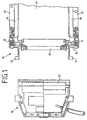
- a subrack 10 is in cross-section and cut-out between profile mounting rails 12, 14 arranged guide brackets 16 and 18 shown by locking connections are attached to the rails 12, 14.
- the guide holders 16, 18 extend along upper and lower cover plates 20, 22 and have unspecified Grooves with their open long sides facing each other. Side walls 21 of the rack 10 can be screwed to the profile rails 12, 14.
- the side walls 21, cover plates 20, 22, profile rails 12, 14 and a rear Cover plate are made of metal, especially aluminum, for shielding functions to be able to exercise.
- Construction boards such as European plug-in cards 24 are in the grooves of the guide holders 16, 18 used, the electrical or electronic components not shown and in Embodiment at the front end carry a knife bar 26 which is in a female connector 28 e.g. the crimp, wire-wrap or solder design can be inserted.
- circuit board 24 and connector 26 are more extensive Assembling outgoing guide elements 32, 34 shown, which are not specified in Engage grooves in the cable housing 10 in order to insert the cable housing 10 easily and precisely to be able to.
- the connector 26 passes through a metal front panel 36, which also with the rails 12 and 14 is screwed.
- the front plate 36 is made of metal like Aluminum or from a metallized material to perform a shielding function can.
- a cable housing 38 is made of two different ones Housing shells 40 and 42 assembled, each housing shell 40, 42 in turn from Side walls 44, 46, rear wall 48, 50 and base or base wall 52, 54 is made. 2 and 4, the base wall 52 of the housing part 40 has a step formed by a slope 54. However, this is not a mandatory feature.
- the base wall 54 of the housing part 42 does not have a recess 58 due to one dome-like projection of the connector designed as a female connector 60 on.
- the base wall 52 of the housing shell 40 is at its front edge as Spring leg 62 formed, which is inside the rack when the connector is inserted 10 extends and along either one spring leg 64 an adjacent one Front plate 66 or a contact leg 68 of an adjacent cable housing 30 extends.
- the spring leg 62 extending integrally from the base wall 52 serves as a receptacle for a Spring element 70 which extends substantially over the width of the base wall 52 and is bent outwards in order to make sufficient electrically conductive contact with the assigned contact leg 64 of the front plate 66 or a contact leg 68 one adjacent cable housing and thus ensure the desired shielding.
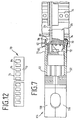
- the spring 70 is a kind of leaf spring with a wider one on the outside along the base wall 52 extending strip-shaped longitudinal edge 72 which at a Step 75 adjoins the base wall 52 in order to merge flush with it.
- the opposite longitudinal edge 74 which is narrower, is also strip-shaped and extends on the inside along the web-shaped edge 76 of the spring leg 62.
- the strip 74 of the spring element 70 lies by spring tension conditionally with its outer edge 76, preferably in a groove-like recess 80 extends along the inner surface of the spring leg 62 and the transition between the web-like tip 78 and one that runs parallel to the outer surface of the base wall 52 Section 82 forms.
- FIG. 7 further clarifies that the web-shaped edge 78 faces inwards is curved.
- the strip-shaped longitudinal edges 72, 74 of the spring element 70 are through to each other spaced transverse strips 84 connected, the clear distance between the transverse strips 84 is greater than the width of the transverse strips 84 themselves.
- the longitudinal edge 72 of the spring element 70 is preferably glued to the base wall 52 connected. However, there are also other fastening options. So they can Longitudinal edges 72, 74 inserted into cavities of the spring leg 62 and via counter bearings be secured. In this respect, however, is based on sufficient constructions and also on Referenced possibilities that are known from DE 41 14 484 C2.
- the spring leg running along the base wall 54 having the recess 58 68 - as the basic illustration of FIG. 11 illustrates - of a sheet metal element 86, namely formed by its front bent edge 88, which has the function can exercise a frictional cutting edge.
- the sheet metal element 86 is with the base wall 54 screwed, the sheet metal element 86 being folded in the area of the base wall 54 ensure a necessary stability.
- the folds that are exemplary with the Reference numerals 90 are provided in corresponding recesses 92 in the base wall 54 intervention.
- the sheet metal element 86 can be chosen so thin that the desired ones are achieved Shielding effect, the cable housing 38 does not have the required side dimensions exceeds that an installation in the rack 10 would no longer be possible.
- FIG. 9 From the sectional view of FIG. 9 as well as from the perspective view according to 10 also shows that at a distance from the front of the housing part 40 on the outside wall there is a receptacle 106 for a spring element 108, via which an electrical conductive contact to an adjacent cable housing can be made.
- the Recording 106 a front chamber-like depression 109 and a rear step-shaped Indentation 110, into which the spring element 108 can be introduced and fixed.
- the slit-shaped and extending almost over the entire width of the housing shell 40 Depressions 109, 110 run parallel to one another.
- the geometry of the spring element 108 can be that of the spring element 70 correspond, consequently has an inwardly angled edge in its upper region that surrounds a web 112 delimiting the chamber 109 on the outside, as is also the case is illustrated by Fig. 4.
- the longitudinal edge of the spring element can be glued in the recess 110 or in another suitably e.g. can also be determined by bearings and abutments.
- FIGS. 5 to 7 differs from those previously described in that a cable housing 114 is composed of two identical shells 116, 118 is identical to the housing shell with respect to the leg configurations 40 match.
- a cable housing 114 is composed of two identical shells 116, 118 is identical to the housing shell with respect to the leg configurations 40 match.
- the invention is independent of the preferred embodiments described above Teaching applicable wherever a shield between the interface a cable housing and a shielded other housing is desired.
Landscapes
- Engineering & Computer Science (AREA)
- Microelectronics & Electronic Packaging (AREA)
- Details Of Connecting Devices For Male And Female Coupling (AREA)
Abstract
Description
- Fig. 1
- ein Kabelgehäuse mit Steckverbinder zum Einstecken in einen Baugruppenträger, teilweise im Schnitt dargestellt,
- Fig. 2
- einen Ausschnitt eines Baugruppenträgers mit Steckverbinder aufnehmenden Kabelgehäusen einer ersten Ausführungsform, teilweise in Explosionsdarstellung,
- Fig. 3
- eine vergrößerte Darstellung des Bereichs X in Fig. 2,
- Fig. 4
- eine vergrößerte Darstellung des Bereichs Y in Fig. 2,
- Fig. 5
- einen Ausschnitt eines Baugruppenträgers mit Steckverbinder aufweisenden Kabelgehäusen einer zweiten Ausführungsform, teilweise in Explosionsdarstellung,
- Fig. 6
- eine vergrößerte Darstellung des Bereichs X in Fig. 5,
- Fig. 7
- eine vergrößerte Darstellung des Bereichs Y in Fig. 5,
- Fig. 8
- im Ausschnitt einen Frontbereich eines Baugruppenträgers mit Kabelgehäuse,
- Fig. 9
- einen Schnitt durch das Kabelgehäuse gemäß Fig. 8,
- Fig. 10
- eine weitere Ausführungsform eines Kabelgehäuses mit Baugruppenträger, perspektivisch und im Ausschnitt,
- Fig. 11
- eine perspektivische Darstellung, teilweise auseinandergezogen, einer weiteren Ausführungsform eines Kabelgehäuses und
- Fig. 12
- ein Blattfederelement.
Claims (20)
- Kabelgehäuse (30, 38, 114) zur Aufnahme eines Steckverbinders (28, 60) wie Feder- oder Messerleiste zum Verbinden mit einem Steckverbinder (26) wie Messer- oder Federleiste einer in einem abgeschirmten Gehäuse wie Baugruppenträger (10) anordbaren Baugruppe (24), wobei das Kabelgehäuse zwei miteinander verbindbare Gehäuseteile mit Seitenwänden (44, 46), Rückwand (48, 50) und Basiswand (52, 54) umfaßt,
dadurch gekennzeichnet,
daß von der Basiswand (52, 54) der Gehäuseschale (40, 42, 116, 118) ausgehend oder entlang dieser sich erstreckend ein Kontakt- und/oder Federschenkel (62, 68, 98) zur Ausbildung einer elektrisch leitenden Verbindung mit einem angrenzenden weiteren Kabelgehäuse oder einem Abschnitt des abgeschirmten Gehäuses (10) ausgeht. - Kabelgehäuse nach Anspruch 1,
dadurch gekennzeichnet,
daß der Kontakt- bzw. Federschenkel (62) integral mit der Basiswand (52) ausgebildet ist. - Kabelgehäuse nach Anspruch 1 oder 2,
dadurch gekennzeichnet,
daß der Federschenkel (62) vorderer stirnrandseitiger Abschnitt der Basiswand (52) ist, daß außenseitig und bündig in die Basiswand übergehend ein Federelement (70) verläuft, die den Federschenkel endseitig umgibt sich bis zur Innenseite des Federschenkels erstreckt. - Kabelgehäuse nach zumindest einem der vorhergehenden Ansprüche,
dadurch gekennzeichnet,
daß das Federelement (70) parallel zum vorderen Längsrand (78) des Federschenkels (62) verlaufend und außen- und innenseitig an der Basiswand (52) anliegend äußere und innere Ränder bildende Längsstreifen (72, 74) aufweist, die über senkrecht zu diesen verlaufende und zueinander beabstandete Querstreifen (84) verbunden sind. - Streckergehäuse nach zumindest einem der vorhergehenden Ansprüche,
dadurch gekennzeichnet,
daß die Querstreifen (84) in ihren außen entlang der Basiswand (52) verlaufenden Bereichen nach außen gebogen sind. - Kabelgehäuse nach zumindest einem der vorhergehenden Ansprüche,
dadurch gekennzeichnet,
daß der äußere Längsstreifen (72) des Federelementes (70) randseitig an einer Stufe (75) der Basiswand (52) angrenzt. - Kabelgehäuse nach zumindest einem der vorhergehenden Ansprüche,
dadurch gekennzeichnet,
daß der äußere Längsstreifen (72) des Federelementes (70) an der Basiswand (52) befestigt wie geklebt ist. - Kabelgehäuse nach zumindest einem der vorhergehenden Ansprüche,
dadurch gekennzeichnet,
daß der innere Längsstreifen (74) des Federelementes (70) randseitig in einer Längsnut (80) der Innenfläche der Basiswand (52) verläuft. - Kabelgehäuse nach zumindest einem der vorhergehenden Ansprüche,
dadurch gekennzeichnet,
daß die Querstreifen (72, 74) des Federelementes (70) senkrecht zu einer außenwandigen Längsrippe der Basiswand (52) verlaufen. - Kabelgehäuse nach zumindest einem der vorhergehenden Ansprüche,
dadurch gekennzeichnet,
daß die Basiswand (52) stirnrandseitig nach innen abgewinkelt ist. - Kabelgehäuse nach zumindest einem der vorhergehenden Ansprüche,
dadurch gekennzeichnet,
daß die innenwandseitige Längsnut (80) des Federschenkels (62) zwischen dem nach innen abgewinkelten Längsrand (78) und parallel zur Außenfläche der Basiswand (52) verlaufender Innenfläche (82) des Federschenkels (62) verläuft. - Kabelgehäuse nach zumindest einem der vorhergehenden Ansprüche,
dadurch gekennzeichnet,
daß der Kontaktschenkel gleich dem Federschenkel (62) ausgebildet ist. - Kabelgehäuse nach zumindest einem der vorhergehenden Ansprüche, wobei zumindest eine Gehäuseschale (42) eine von deren vorderem Rand ausgehende Ausnehmung bzw. Aussparung (58) aufweist,
dadurch gekennzeichnet,
daß die Aussparung (58) von einem mit der Gehäuseschale (42) verbindbare Blechelement (86) mit parallel zum Längsrand der Gehäuseschale verlaufenden und über diesen vorstehenden Randabschnitt (88) abgedeckt ist, der Schenkel wie Kontaktschenkel (68) zur Ausbildung einer leitenden Verbindung mit einem angrenzenden weiteren Kabelgehäuse oder einem Abschnitt des Baugruppenträgers (10) ist. - Kabelgehäuse nach zumindest einem der vorhergehenden Ansprüche,
dadurch gekennzeichnet,
daß der Randabschnitt (88) des Blechelementes (86) nach innen umgebogen ist. - Kabelgehäuse nach zumindest einem der vorhergehenden Ansprüche,
dadurch gekennzeichnet,
daß das Blechelement (86) gehäuseseitig zumindest abschnittsweise abgekantet ist. - Kabelgehäuse nach zumindest einem der vorhergehenden Ansprüche,
dadurch gekennzeichnet,
daß das Blechelement (86) mit der Basiswandung (54) verschraubt ist. - Kabelgehäuse nach zumindest einem der vorhergehenden Ansprüche,
dadurch gekennzeichnet,
daß Abkantungen (90) des Blechelementes (86) in angepaßte Aufnahmen (92) der Basiswandung (54) eingreifen. - Kabelgehäuse nach zumindest einem der vorhergehenden Ansprüche,
dadurch gekennzeichnet,
daß außenseitig entlang der Basiswandung (54) der Gehäuseschale (42) und die Aussparung (58) abdeckend ein Aufsatz (98) befestigt ist, entlang dessen Stirnseite sich ein an dem abgeschirmten Gehäuse wie Baugruppenträger (10) oder einem Abschnitt von diesem wie Frontplatte (36) anliegendes Federelement (102) erstreckt. - Kabelgehäuse nach zumindest einem der vorhergehenden Ansprüche,
dadurch gekennzeichnet,
daß beabstandet zum integral mit der Basiswand (52) ausgebildeten Feder- bzw. Kontaktschenkel (62) und parallel zu dessen Längsrand (78) außenflächig in der Basiswand über oder nahezu über dessen Breite eine Aufnahme (106) für ein zweites Feder- wie Blattfederelement (108) vorgesehen ist. - Kabelgehäuse nach zumindest einem der vorhergehenden Ansprüche,
dadurch gekennzeichnet,
daß in der Außenfläche der Basiswand (52) eine parallel zu deren Stirnrand verlaufende kammer- oder schlitzförmige Aussparung zur Aufnahme eines Längsrand des entlang der Basiswand verlaufenden Federelements (108) wie Blattfeder verläuft, dessen anderer Längsrand von einem U- bzw. keisabschnittförmig gebogenen Endbereichs des Federelementes ausgeht, der einen eine kammerförmige Aussparung (109) außenseitig begrenzenden Steg (112) umgibt.
Applications Claiming Priority (2)
| Application Number | Priority Date | Filing Date | Title |
|---|---|---|---|
| DE19646063 | 1996-11-08 | ||
| DE19646063A DE19646063C2 (de) | 1996-11-08 | 1996-11-08 | Kabelgehäuse |
Publications (2)
| Publication Number | Publication Date |
|---|---|
| EP0851537A2 true EP0851537A2 (de) | 1998-07-01 |
| EP0851537A3 EP0851537A3 (de) | 1999-04-07 |
Family
ID=7811011
Family Applications (1)
| Application Number | Title | Priority Date | Filing Date |
|---|---|---|---|
| EP97119608A Withdrawn EP0851537A3 (de) | 1996-11-08 | 1997-11-10 | Kabelgehäuse |
Country Status (2)
| Country | Link |
|---|---|
| EP (1) | EP0851537A3 (de) |
| DE (1) | DE19646063C2 (de) |
Cited By (1)
| Publication number | Priority date | Publication date | Assignee | Title |
|---|---|---|---|---|
| DE29817708U1 (de) * | 1998-09-01 | 2000-01-13 | AEG Intermas GmbH, 64546 Mörfelden-Walldorf | Kabelgehäuse |
Families Citing this family (2)
| Publication number | Priority date | Publication date | Assignee | Title |
|---|---|---|---|---|
| DE29801984U1 (de) | 1998-02-06 | 1998-03-26 | Schmitt, Fred R., 74388 Talheim | Steckverbinder-Gehäuse im 19 Zoll-Gerätesystem |
| DE19842447C2 (de) * | 1998-09-16 | 2002-02-07 | Siemens Ag | Steckverbindersystem für eine Telekommunikations-Anschlußdose oder für ein Verteiler-Steckfeld |
Family Cites Families (10)
| Publication number | Priority date | Publication date | Assignee | Title |
|---|---|---|---|---|
| DE2611941C2 (de) * | 1976-03-20 | 1982-12-09 | Erni Elektroapparate Gmbh, 7321 Adelberg | Steckergehäuse |
| US4653836A (en) * | 1983-07-06 | 1987-03-31 | Amp Incorporated | Shielded electrical connector |
| DE8911590U1 (de) * | 1989-09-28 | 1990-01-04 | Siemens AG, 1000 Berlin und 8000 München | Elektrische Verbindung von Abschirmungen mehrpoliger Stecker mit der Erdpotentialschicht einer Verdrahtungsplatte |
| DE4016797C2 (de) * | 1990-05-25 | 1998-04-09 | Daimler Benz Aerospace Ag | Vorrichtung zur hochfrequenzdichten Abschirmung eines Einschub-Gehäuses |
| DE4039902A1 (de) * | 1990-12-14 | 1992-06-17 | Messer Griesheim Gmbh | Steckverbinder oder -vorrichtung |
| DE59200646D1 (de) * | 1991-05-03 | 1994-11-24 | Licentia Gmbh | Baugruppenträger. |
| DE4114484C2 (de) * | 1991-05-03 | 1993-12-02 | Licentia Gmbh | Baugruppenträger |
| DE4237447A1 (de) * | 1992-11-06 | 1994-05-11 | Licentia Gmbh | Baugruppenträger |
| DE9421093U1 (de) * | 1994-05-11 | 1995-04-13 | ITT Cannon GmbH, 71384 Weinstadt | Geschirmter Kabelstecker und Kombination aus einem solchen Kabelstecker und einer Steckkarte |
| DE29505601U1 (de) * | 1995-03-31 | 1995-05-24 | Amphenol-Tuchel Electronics Gmbh, 74080 Heilbronn | EMV-dichte Gehäuse für schwere Steckverbinder der Serie C146 |
-
1996
- 1996-11-08 DE DE19646063A patent/DE19646063C2/de not_active Expired - Lifetime
-
1997
- 1997-11-10 EP EP97119608A patent/EP0851537A3/de not_active Withdrawn
Cited By (1)
| Publication number | Priority date | Publication date | Assignee | Title |
|---|---|---|---|---|
| DE29817708U1 (de) * | 1998-09-01 | 2000-01-13 | AEG Intermas GmbH, 64546 Mörfelden-Walldorf | Kabelgehäuse |
Also Published As
| Publication number | Publication date |
|---|---|
| DE19646063C2 (de) | 2002-04-04 |
| EP0851537A3 (de) | 1999-04-07 |
| DE19646063A1 (de) | 1998-05-14 |
Similar Documents
| Publication | Publication Date | Title |
|---|---|---|
| DE4004385C2 (de) | Elektrischer Steckverbinder | |
| DE3883467T2 (de) | Abgeschirmtes glied eines elektrischen steckverbinders mit montagemitteln. | |
| EP1166396B1 (de) | Steckverbindung mit abschirmung | |
| DE69207217T2 (de) | Abgeschirmte elektrische Verbinderanordnung | |
| DE69126105T2 (de) | Ein Modul-Koaxialsteckverbinder | |
| DE3886816T2 (de) | Elektrischer Steckverbinder. | |
| DE69121270T2 (de) | Zweiteilige Buchseneinheit für modularen Steckeraufbau | |
| DE69309761T2 (de) | Elektrischer Verbinder und Abschirmung für Oberflächenmontage | |
| DE19841216A1 (de) | Buchsenstecker für elektrische Verbinder mit Kodierrippe | |
| EP0105150B1 (de) | Führungsschiene für elektronische Baugruppenträger | |
| EP0866650B1 (de) | Anordnung zur hochfrequenzdichten Abschirmung | |
| DE10057833B4 (de) | Steckverbinder für mehradrige Daten- und/oder Telekommunikations-Kabel | |
| EP0129883A2 (de) | Frontsystem für in Baugruppenträger einschiebbare Steckbaugruppen und rahmenartige Baugruppenträger zu deren Aufnahme | |
| EP0864188B1 (de) | Bandkabel mit schirmanschluss | |
| EP1105939B1 (de) | Anreihbare busschiene | |
| DE8803544U1 (de) | Baugruppenträger mit abgeschirmten Steckbaugruppen | |
| DE60311021T2 (de) | Abgeschirmter Steckerzusammenbau | |
| DE69507462T2 (de) | Abschirmdeckel mit zugehörigem Abschirmverfahren | |
| DE60004222T2 (de) | Verfahren und vorrichtung zur abschirmung einer steckeranordnung mit elastischen fingern | |
| EP2568552A2 (de) | Kabeltragvorrichtung | |
| EP0415246A2 (de) | Baugruppenträger | |
| DE19646063C2 (de) | Kabelgehäuse | |
| WO2001013473A1 (de) | Geschirmter elektrischer steckverbinder | |
| DE1929219A1 (de) | Elektrischer Anschlussstecker | |
| DE19609887C1 (de) | Gerätechassis für elektronische Geräte |
Legal Events
| Date | Code | Title | Description |
|---|---|---|---|
| PUAI | Public reference made under article 153(3) epc to a published international application that has entered the european phase |
Free format text: ORIGINAL CODE: 0009012 |
|
| AK | Designated contracting states |
Kind code of ref document: A2 Designated state(s): AT BE CH DE DK ES FI FR GB GR IE IT LI LU MC NL PT SE |
|
| AX | Request for extension of the european patent |
Free format text: AL;LT;LV;RO;SI |
|
| PUAL | Search report despatched |
Free format text: ORIGINAL CODE: 0009013 |
|
| AK | Designated contracting states |
Kind code of ref document: A3 Designated state(s): AT BE CH DE DK ES FI FR GB GR IE IT LI LU MC NL PT SE |
|
| AX | Request for extension of the european patent |
Free format text: AL;LT;LV;RO;SI |
|
| 17P | Request for examination filed |
Effective date: 19990428 |
|
| AKX | Designation fees paid | ||
| STAA | Information on the status of an ep patent application or granted ep patent |
Free format text: STATUS: THE APPLICATION HAS BEEN WITHDRAWN |
|
| 18W | Application withdrawn |
Withdrawal date: 20000120 |
|
| REG | Reference to a national code |
Ref country code: DE Ref legal event code: 8566 |