EP0851617A2 - Dispositif optique pour amplifier des signaux multiplexés en longueur d'onde - Google Patents
Dispositif optique pour amplifier des signaux multiplexés en longueur d'onde Download PDFInfo
- Publication number
- EP0851617A2 EP0851617A2 EP97310379A EP97310379A EP0851617A2 EP 0851617 A2 EP0851617 A2 EP 0851617A2 EP 97310379 A EP97310379 A EP 97310379A EP 97310379 A EP97310379 A EP 97310379A EP 0851617 A2 EP0851617 A2 EP 0851617A2
- Authority
- EP
- European Patent Office
- Prior art keywords
- signals
- subplurality
- network
- frequency router
- amplified
- Prior art date
- Legal status (The legal status is an assumption and is not a legal conclusion. Google has not performed a legal analysis and makes no representation as to the accuracy of the status listed.)
- Withdrawn
Links
- 230000003287 optical effect Effects 0.000 title claims abstract description 41
- 230000001902 propagating effect Effects 0.000 claims abstract description 44
- 230000003321 amplification Effects 0.000 claims abstract description 35
- 238000003199 nucleic acid amplification method Methods 0.000 claims abstract description 35
- 230000008878 coupling Effects 0.000 claims description 5
- 238000010168 coupling process Methods 0.000 claims description 5
- 238000005859 coupling reaction Methods 0.000 claims description 5
- 230000002457 bidirectional effect Effects 0.000 claims description 4
- 238000000034 method Methods 0.000 claims 12
- 239000000470 constituent Substances 0.000 claims 1
- 210000001520 comb Anatomy 0.000 description 12
- 238000011144 upstream manufacturing Methods 0.000 description 4
- 238000010586 diagram Methods 0.000 description 3
- 230000002238 attenuated effect Effects 0.000 description 2
- 238000009434 installation Methods 0.000 description 2
- 239000013307 optical fiber Substances 0.000 description 2
- 229910052761 rare earth metal Inorganic materials 0.000 description 2
- 229910052691 Erbium Inorganic materials 0.000 description 1
- UYAHIZSMUZPPFV-UHFFFAOYSA-N erbium Chemical compound [Er] UYAHIZSMUZPPFV-UHFFFAOYSA-N 0.000 description 1
- 239000000835 fiber Substances 0.000 description 1
- 150000002500 ions Chemical class 0.000 description 1
- 238000012423 maintenance Methods 0.000 description 1
- 230000000644 propagated effect Effects 0.000 description 1
- -1 rare earth ions Chemical class 0.000 description 1
- 150000002910 rare earth metals Chemical class 0.000 description 1
Images
Classifications
-
- H—ELECTRICITY
- H04—ELECTRIC COMMUNICATION TECHNIQUE
- H04B—TRANSMISSION
- H04B10/00—Transmission systems employing electromagnetic waves other than radio-waves, e.g. infrared, visible or ultraviolet light, or employing corpuscular radiation, e.g. quantum communication
- H04B10/29—Repeaters
- H04B10/291—Repeaters in which processing or amplification is carried out without conversion of the main signal from optical form
- H04B10/297—Bidirectional amplification
- H04B10/2971—A single amplifier for both directions
-
- H—ELECTRICITY
- H01—ELECTRIC ELEMENTS
- H01S—DEVICES USING THE PROCESS OF LIGHT AMPLIFICATION BY STIMULATED EMISSION OF RADIATION [LASER] TO AMPLIFY OR GENERATE LIGHT; DEVICES USING STIMULATED EMISSION OF ELECTROMAGNETIC RADIATION IN WAVE RANGES OTHER THAN OPTICAL
- H01S3/00—Lasers, i.e. devices using stimulated emission of electromagnetic radiation in the infrared, visible or ultraviolet wave range
- H01S3/05—Construction or shape of optical resonators; Accommodation of active medium therein; Shape of active medium
- H01S3/06—Construction or shape of active medium
- H01S3/063—Waveguide lasers, i.e. whereby the dimensions of the waveguide are of the order of the light wavelength
- H01S3/067—Fibre lasers
- H01S3/06754—Fibre amplifiers
-
- H—ELECTRICITY
- H01—ELECTRIC ELEMENTS
- H01S—DEVICES USING THE PROCESS OF LIGHT AMPLIFICATION BY STIMULATED EMISSION OF RADIATION [LASER] TO AMPLIFY OR GENERATE LIGHT; DEVICES USING STIMULATED EMISSION OF ELECTROMAGNETIC RADIATION IN WAVE RANGES OTHER THAN OPTICAL
- H01S3/00—Lasers, i.e. devices using stimulated emission of electromagnetic radiation in the infrared, visible or ultraviolet wave range
- H01S3/05—Construction or shape of optical resonators; Accommodation of active medium therein; Shape of active medium
- H01S3/06—Construction or shape of active medium
- H01S3/063—Waveguide lasers, i.e. whereby the dimensions of the waveguide are of the order of the light wavelength
- H01S3/067—Fibre lasers
- H01S3/06754—Fibre amplifiers
- H01S3/06787—Bidirectional amplifier
Definitions
- This invention relates to fiber-optic telecommunication networks. More particularly, this invention relates to amplification of wavelength-division-multiplexed (WDM) optical signals propagating through such networks.
- WDM wavelength-division-multiplexed
- Wavelength-division-multiplexing increases the capacity of existing fiber-optic networks by enabling multiple signals of different wavelengths to propagate simultaneously through individual fiber-optic lines, known as links.
- Each link supports bidirectional signal transport, that is, multiple signals propagating simultaneously both upstream and downstream through a link.
- bit is a binary digit, the basic unit of computer data, and a "gigabit” is a billion bits).
- tens of signals, each having a different wavelength can propagate simultaneously through a single fiber-optic link.
- Fiber-optic networks One problem in large fiber-optic networks is attenuation (or gradual loss) of fiber-optic signals as they propagate from their source. Such attenuated fiber-optic signals must be repowered, or amplified, before the information carried by those signals is lost. Signal amplification is accomplished by installing optical amplifiers at particular locations throughout the network. Generally, optical amplifiers are needed every 50 kilometers from a signal source.
- the typical optical amplifier is limited, however, to amplifying signals propagating in only one direction relative to its input/output orientation.
- a pair of amplifiers would generally be required at every location requiring signal amplification, one for amplifying signals propagating in one direction and the other for amplifying signals propagating in the opposite direction.
- optical amplifiers will not pass signals propagating in the direction opposite their input/output orientation, thus negating the placement of two amplifiers back-to-back on the same link.
- Known fiber-optic networks undesirably run parallel fiber-optic links. Each link is limited to unidirectional signal propagation to permit signal amplification through an optical amplifier on that link. Such networks undesirably increase excess link capacity by having two links where one would likely be sufficient to handle the volume of signal flow propagating in each direction.
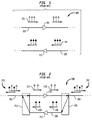
- FIG. 1 A portion of such a conventional prior art network is shown in FIG. 1.
- a group or "comb" of WDM signals 101 is shown propagating left to right (with white arrowheads) through fiber-optic link 103 to optical amplifier 105, while a second comb of WDM signals 107 is shown propagating in the opposite direction (right to left with black arrowheads) through fiber-optic link 109 to second optical amplifier 111.
- this network incurs additional costs associated with the installation and maintenance of parallel links and amplifiers.
- Fiber-optic networks have been proposed that avoid the installation of parallel links by advantageously employing frequency routers.
- Frequency routers can separate and combine upstream and downstream WDM signals by multiplexing and demultiplexing signals based on signal wavelength. Note that when referring to the operation of frequency routers, the terms "wavelength" and "frequency” are interchangeable.
- a first frequency router routes signals propagating in one direction to, for example, a branch link, while routing signals of the opposite direction to the mainline link.
- the branch link contains a second amplifier for amplifying those signals routed to it by the first frequency router, while the signals on the mainline link are amplified by an amplifier located there.
- a second frequency router then returns the amplified signals from the branch link to the mainline link.
- FIG. 2 A portion of such a proposed network is shown in FIG. 2.
- Two combs of oppositely propagating WDM signals 201 are propagating through mainline fiber-optic link 203.
- signals 207 which are propagating right to left and are shown in FIG. 2 with black arrowheads, are routed to branch link 209 where they are amplified by optical amplifier 211.
- Amplified signals 208 are then routed by frequency router 213 to link 203 where they propagate as one of two combs of WDM signals 215.
- Signals 217 which are propagating left to right and are shown in FIG. 2 with white arrowheads, are routed by frequency router 213 to optical amplifier 219 for amplification.
- Amplified signals 218 are then routed by frequency router 205 to link 203 where they propagate as one of two combs of WDM signals 201. While this arrangement eliminates the second parallel fiber-optic link shown in FIG. 1, advantageously avoiding the undesirable increase in excess link capacity and associated costs of installing and maintaining parallel links, this arrangement still undesirably requires two amplifiers at every location requiring signal amplification.
- Optical amplifiers are very expensive network components.
- a network spanning long distances, such as, for example, a long distance telephone network incurs significant costs by providing two amplifiers at each location requiring signal amplification.
- a reduction therefore in the number of amplifiers required to properly amplify bidirectionally propagating WDM signals would result in significant cost savings.
- an amplification circuit for use in a wavelength-division-multiplexed (WDM) fiber-optic network that can amplify signals propagating simultaneously in both directions, upstream and downstream, through a single fiber-optic link.
- the amplification circuit employs a single optical amplifier and at least one frequency router. Combs of WDM signals propagating in one direction are multiplexed with combs of WDM signals propagating in the opposite direction, amplified through a single optical amplifier, and then demultiplexed and routed in their original propagation directions. Fiber-optic networks using the amplification circuit are also provided.
- the present invention requires only a single optical amplifier to amplify wavelength-division-multiplexed (WDM) signals propagating simultaneously both upstream and downstream through a fiber-optic link.
- WDM enables multiple signals, each having a unique wavelength, to propagate simultaneously and bidirectionally through a single link.
- Use of the invention in a WDM fiber-optic network eliminates by as much as half the number of optical amplifiers required to amplify WDM fiber-optic signals, while still providing proper amplification of those signals throughout the network without increasing excess link capacity.
- a fiber-optic network typically includes a plurality of nodes for adding signals to, dropping signals from, and routing signals through the network; a plurality of fiber-optic links for propagating signals between nodes; and a plurality of optical amplifiers to combat signal losses incurred during signal propagation from signal sources.
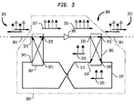
- FIG. 3 illustrates a portion of fiber-optic network 300 according to the present invention.
- the portion shown includes mainline fiber-optic link 301, which is representative of any link in the network exceeding approximately 50 kilometers in length, and amplification circuit 303.
- Amplification circuit 303 includes frequency routers 305 and 307 and optical amplifier 309.
- Optical signal loss, or optical signal attenuation, in the network of FIG. 3 is typically 0.3 dB per kilometer.
- signal amplification should occur approximately every 50 kilometers with a signal gain of approximately 30 dB.
- the particular gain and proximity of amplifiers can of course be varied according to the particular needs and characteristics of the network (e.g., inherent losses, locations of signal sources, etc.). Failure to properly amplify attenuated signals can result in a loss of the information carried by those signals.
- Optical amplifiers are known in the art and generally include a rare earth (e.g., erbium) doped optical fiber, a pumped light source for exciting the rare earth ions, and an optical coupler for coupling the pumped light to the doped optical fiber. Amplification occurs as the propagating signals flow through the doped fibers and are exposed to the stimulated emissions caused by the excited ions.
- a rare earth e.g., erbium
- optical amplifier 309 amplifies optical signals propagating left to right. Signals propagating in the opposite direction (right to left) will not be amplified by, nor will they pass through, amplifier 309. Optical amplifier 309 can thus be considered a unidirectional device.
- amplification circuit 303 Operation of amplification circuit 303 is as follows: two groups of interlaced oppositely propagating combs of WDM signals 311 are propagating on fiber-optic link 301 at port 313 of frequency router 305. Signals 315, propagating right to left and shown in FIG. 3 with black arrowheads, are routed through frequency router 305 to fiber-optic link 317 at port 319. Signals 315 propagate through link 317 to port 341 of frequency router 307. Frequency router 307 then multiplexes (combines) signals 315 with signals propagating left to right, shown with white arrowheads, received at port 323 from another two groups of interlaced oppositely propagating combs of WDM signals 325.
- the multiplexed interlaced combs of WDM signals 327 exit frequency router 307 at port 329 and propagate to optical amplifier 309, where they are amplified.
- Interlaced combs of amplified WDM signals 331 then propagate to port 333 of frequency router 305, where they are demultiplexed (separated).
- the amplified signals originally propagating left to right are routed through frequency router 305 to link 301 at port 313, where they become one of two combs of interlaced oppositely propagating WDM signals 311.
- Amplified signals 335 are routed through frequency router 305 to fiber-optic link 337 at port 339, where they propagate to port 321 of frequency router 307.
- amplified signals 335 are routed to link 301 at port 323, where they return to their original right to left direction of propagation and become one of two combs of oppositely propagating WDM signals 325.
- WDM signals propagating in opposite directions through fiber-optic links can be amplified by an amplification circuit with a single optical amplifier.
- amplification circuits can be used in fiber-optic networks at each location requiring bidirectional signal amplification. Use of such circuits reduces by as much as half the number of optical amplifiers required to properly amplify propagating signals as compared to the previously discussed networks shown in FIGS. 1 and 2. Moreover, use of such circuits does not undesirably increase a network's excess link capacity.
Landscapes
- Physics & Mathematics (AREA)
- Electromagnetism (AREA)
- Engineering & Computer Science (AREA)
- Plasma & Fusion (AREA)
- Optics & Photonics (AREA)
- Computer Networks & Wireless Communication (AREA)
- Signal Processing (AREA)
- Optical Communication System (AREA)
- Light Guides In General And Applications Therefor (AREA)
Applications Claiming Priority (2)
| Application Number | Priority Date | Filing Date | Title |
|---|---|---|---|
| US775473 | 1996-12-30 | ||
| US08/775,473 US5740289A (en) | 1996-12-30 | 1996-12-30 | Optical arrangement for amplifying WDM signals |
Publications (2)
| Publication Number | Publication Date |
|---|---|
| EP0851617A2 true EP0851617A2 (fr) | 1998-07-01 |
| EP0851617A3 EP0851617A3 (fr) | 1999-07-14 |
Family
ID=25104540
Family Applications (1)
| Application Number | Title | Priority Date | Filing Date |
|---|---|---|---|
| EP97310379A Withdrawn EP0851617A3 (fr) | 1996-12-30 | 1997-12-19 | Dispositif optique pour amplifier des signaux multiplexés en longueur d'onde |
Country Status (4)
| Country | Link |
|---|---|
| US (1) | US5740289A (fr) |
| EP (1) | EP0851617A3 (fr) |
| JP (1) | JPH10210014A (fr) |
| CA (1) | CA2224851C (fr) |
Families Citing this family (23)
| Publication number | Priority date | Publication date | Assignee | Title |
|---|---|---|---|---|
| US6188509B1 (en) * | 1997-01-05 | 2001-02-13 | Korea Advanced Institute Science And Technology | Simple bidirectional add/drop amplifier module based on a single multiplexer |
| FR2764998B1 (fr) * | 1997-06-20 | 1999-09-03 | Thomson Csf | Systeme d'amplification optique bidirectionnel |
| DE69942247D1 (de) | 1998-10-26 | 2010-05-27 | Nippon Telegraph & Telephone | Wdm-übertragungsnetzwerkvorrichtung mit sender/empfänger mit optischem schalter mit 2 eingängen und 2 ausgängen |
| US6211978B1 (en) | 1999-02-10 | 2001-04-03 | Anacom Systems, Inc. | Multi-channel wave division multiplexer system |
| US6459528B1 (en) | 2000-05-23 | 2002-10-01 | Avanex Corporation | Optical passive components and bi-directional amplifier |
| KR100351672B1 (ko) * | 2000-06-12 | 2002-09-11 | 한국과학기술원 | 전광자동이득조절 기능을 갖는 양방향 애드/드롭 광증폭기 |
| US6388805B1 (en) * | 2001-03-28 | 2002-05-14 | Sycamore Networks, Inc. | Two fiber support with single optical amplifier |
| KR100378111B1 (ko) * | 2001-04-02 | 2003-03-29 | 삼성전자주식회사 | 광증폭기 및 이를 이용한 양방향 파장분할 다중 광통신시스템 |
| US6819481B2 (en) * | 2001-06-04 | 2004-11-16 | Lucent Technologies Inc. | Bidirectional wave division multiplex systems |
| US6826163B2 (en) | 2001-06-08 | 2004-11-30 | Nextg Networks | Method and apparatus for multiplexing in a wireless communication infrastructure |
| US7127175B2 (en) * | 2001-06-08 | 2006-10-24 | Nextg Networks | Method and apparatus for multiplexing in a wireless communication infrastructure |
| US6826164B2 (en) | 2001-06-08 | 2004-11-30 | Nextg Networks | Method and apparatus for multiplexing in a wireless communication infrastructure |
| US20020191565A1 (en) * | 2001-06-08 | 2002-12-19 | Sanjay Mani | Methods and systems employing receive diversity in distributed cellular antenna applications |
| JP2003198484A (ja) * | 2001-12-26 | 2003-07-11 | Photonixnet Corp | 光中継増幅器および波長多重化装置 |
| US20040042067A1 (en) * | 2002-06-04 | 2004-03-04 | Eiselt Michael H. | Apparatus and method for duplex optical transport using a co-directional optical amplifier |
| KR100450925B1 (ko) * | 2002-09-18 | 2004-10-02 | 삼성전자주식회사 | 파장분할다중 광통신 시스템의 광원 발생장치 |
| US20040198453A1 (en) * | 2002-09-20 | 2004-10-07 | David Cutrer | Distributed wireless network employing utility poles and optical signal distribution |
| US7421207B2 (en) | 2002-12-13 | 2008-09-02 | Pivotal Decisions Llc | Single fiber duplex optical transport |
| US20070003283A1 (en) * | 2005-06-29 | 2007-01-04 | At&T Corp. | Dynamic allocation of bandwidth in a bidirectional optical transmission system |
| US20150098477A1 (en) * | 2013-10-03 | 2015-04-09 | Versitech Limited | Reversible wavelength channels for optical communication networks |
| US10382158B2 (en) | 2013-10-03 | 2019-08-13 | The Hong Kong Polytechnic University | Reversible wavelength channels for optical communication networks |
| WO2019185139A1 (fr) * | 2018-03-28 | 2019-10-03 | Telefonaktiebolaget Lm Ericsson (Publ) | Nœud de réseau optique et réseau optique |
| CN113872694A (zh) * | 2020-06-30 | 2021-12-31 | 华为技术有限公司 | 多芯光纤交织器、光纤放大器、传输系统以及传输方法 |
Family Cites Families (16)
| Publication number | Priority date | Publication date | Assignee | Title |
|---|---|---|---|---|
| DE3885389T2 (de) * | 1987-09-01 | 1994-03-24 | Nippon Electric Co | Optischer Zwischenverstärker. |
| US5204923A (en) * | 1989-07-17 | 1993-04-20 | Pirelli Cavi S.P.A. | Unit for amplifying light signals in optical fiber transmission lines |
| US5035481A (en) * | 1990-08-23 | 1991-07-30 | At&T Bell Laboratories | Long distance soliton lightwave communication system |
| CA2107181C (fr) * | 1992-09-29 | 1998-12-29 | Yoshiaki Tachikawa | Multiplexeur-demultiplexeur a reseau de guides de lumiere comportant des trajets optiques en boucle de retour |
| US5280549A (en) * | 1993-02-05 | 1994-01-18 | National Research Council Of Canada | Frequency dependent optical isolator |
| US5339157A (en) * | 1993-02-19 | 1994-08-16 | At&T Bell Laboratories | Rapidly tunable integrated optical filter |
| DE4326522A1 (de) * | 1993-08-06 | 1995-02-09 | Siemens Ag | Programmierbares optisches Filter und optische Schaltanordnung |
| US5461685A (en) * | 1993-10-18 | 1995-10-24 | At&T Ipm Corp. | Optical passband filter |
| US5434937A (en) * | 1993-11-16 | 1995-07-18 | At&T Corp. | Optical filter having integrated transceivers |
| AU1296695A (en) * | 1993-12-01 | 1995-06-19 | Williams Telecommunications Group, Inc. | Bidirectional optical amplifier |
| US5452124A (en) * | 1994-03-04 | 1995-09-19 | Williams Telecommunications Group, Inc. | Unidirectional amplification for bi-directional transmission using wavelength-division multiplexing |
| US5524014A (en) * | 1994-05-23 | 1996-06-04 | At&T Corp. | Optical frequency translator |
| US5488680A (en) * | 1994-08-24 | 1996-01-30 | At&T Corp. | Frequency routing device having a wide and substantially flat passband |
| US5657406A (en) * | 1994-09-23 | 1997-08-12 | United Technologies Corporation | Efficient optical wavelength multiplexer/de-multiplexer |
| US5600468A (en) * | 1995-02-13 | 1997-02-04 | Jds Fitel Inc. | Apparatus for converting wavelength-division multiplexed optical signals |
| US5633741A (en) * | 1995-02-23 | 1997-05-27 | Lucent Technologies Inc. | Multichannel optical fiber communications |
-
1996
- 1996-12-30 US US08/775,473 patent/US5740289A/en not_active Expired - Lifetime
-
1997
- 1997-12-15 CA CA002224851A patent/CA2224851C/fr not_active Expired - Fee Related
- 1997-12-19 EP EP97310379A patent/EP0851617A3/fr not_active Withdrawn
- 1997-12-22 JP JP9352973A patent/JPH10210014A/ja active Pending
Also Published As
| Publication number | Publication date |
|---|---|
| JPH10210014A (ja) | 1998-08-07 |
| US5740289A (en) | 1998-04-14 |
| CA2224851C (fr) | 2001-07-10 |
| EP0851617A3 (fr) | 1999-07-14 |
| CA2224851A1 (fr) | 1998-06-30 |
Similar Documents
| Publication | Publication Date | Title |
|---|---|---|
| US5740289A (en) | Optical arrangement for amplifying WDM signals | |
| US6359730B2 (en) | Amplification of an optical WDM signal | |
| US5812306A (en) | Bidirectional WDM optical communication systems with bidirectional optical amplifiers | |
| US5742416A (en) | Bidirectional WDM optical communication systems with bidirectional optical amplifiers | |
| US6597482B1 (en) | Multiplexing/demultiplexing apparatus for wavelength division multiplexed system and wavelength division multiplexed passive optical subscriber networks using the same apparatus | |
| US6411407B1 (en) | Method for providing a bidirectional optical supervisory channel | |
| KR100334432B1 (ko) | 하나의도파관열격자다중화기를이용한양방향애드/드롭광증폭기모듈 | |
| US6449072B1 (en) | Add/drop multiplexer | |
| US6377375B1 (en) | Optical wavelength division multiplexed signal amplifying repeater and optical communication transmission line with very large capacity | |
| US6081368A (en) | Optical amplifier for bi-directional WDM optical communications systems | |
| US6512613B1 (en) | WDM transmission repeater, WDM transmission system and WDM transmission method | |
| US6256140B1 (en) | Optical amplifying apparatus for transmitting wavelength division multiplexed signal light and optical network apparatus with using the same | |
| US20050254819A1 (en) | Optical in-line amplifier and wavelength-division multiplexer | |
| US8503881B1 (en) | Systems for extending WDM transmission into the O-band | |
| JPH11215058A (ja) | 超広帯域波長分散補償デバイス | |
| JP3149916B2 (ja) | 波長多重光中継増幅装置 | |
| US6781749B2 (en) | Interleaving combiner for a bidirectional wavelength-division multiplexing system | |
| EP0967752A2 (fr) | Système de transmission à multiplexage des ondes | |
| US7831148B2 (en) | Optical network and amplifier node therefore | |
| US7031613B1 (en) | Chromatic dispersion compensation by sub-band | |
| US6529320B2 (en) | C and L band laminated fabric optical amplifier | |
| WO2003094398A1 (fr) | Architecture de systeme de transport optique pour connexion de terminal distant | |
| JPH11174383A (ja) | 光アイソレータ回路及び光増幅器 | |
| JP3445738B2 (ja) | 光増幅器 | |
| JP2001505728A (ja) | 複数の分岐ユニットからの挿入/抜き出し光信号ラインを結合する方法及び装置 |
Legal Events
| Date | Code | Title | Description |
|---|---|---|---|
| PUAI | Public reference made under article 153(3) epc to a published international application that has entered the european phase |
Free format text: ORIGINAL CODE: 0009012 |
|
| AK | Designated contracting states |
Kind code of ref document: A2 Designated state(s): DE FR GB |
|
| AX | Request for extension of the european patent |
Free format text: AL;LT;LV;MK;RO;SI |
|
| PUAL | Search report despatched |
Free format text: ORIGINAL CODE: 0009013 |
|
| AK | Designated contracting states |
Kind code of ref document: A3 Designated state(s): AT BE CH DE DK ES FI FR GB GR IE IT LI LU MC NL PT SE |
|
| AX | Request for extension of the european patent |
Free format text: AL;LT;LV;MK;RO;SI |
|
| RIC1 | Information provided on ipc code assigned before grant |
Free format text: 6H 04B 10/24 A, 6H 04B 10/17 B, 6H 04J 14/02 B |
|
| 17P | Request for examination filed |
Effective date: 19990819 |
|
| AKX | Designation fees paid |
Free format text: DE FR GB |
|
| STAA | Information on the status of an ep patent application or granted ep patent |
Free format text: STATUS: THE APPLICATION IS DEEMED TO BE WITHDRAWN |
|
| 18D | Application deemed to be withdrawn |
Effective date: 20030701 |