EP0852060B1 - Actionneur lineaire electromagnetique a plateaux mobiles et regulateur de fluides a vannes pilotees par un tel actionneur - Google Patents
Actionneur lineaire electromagnetique a plateaux mobiles et regulateur de fluides a vannes pilotees par un tel actionneur Download PDFInfo
- Publication number
- EP0852060B1 EP0852060B1 EP96934899A EP96934899A EP0852060B1 EP 0852060 B1 EP0852060 B1 EP 0852060B1 EP 96934899 A EP96934899 A EP 96934899A EP 96934899 A EP96934899 A EP 96934899A EP 0852060 B1 EP0852060 B1 EP 0852060B1
- Authority
- EP
- European Patent Office
- Prior art keywords
- actuator
- magnetic
- valve
- control means
- axis
- Prior art date
- Legal status (The legal status is an assumption and is not a legal conclusion. Google has not performed a legal analysis and makes no representation as to the accuracy of the status listed.)
- Expired - Lifetime
Links
- 239000012530 fluid Substances 0.000 title claims description 14
- 125000006850 spacer group Chemical group 0.000 claims description 21
- 230000005284 excitation Effects 0.000 description 12
- 230000004907 flux Effects 0.000 description 11
- 239000003380 propellant Substances 0.000 description 9
- 238000006073 displacement reaction Methods 0.000 description 6
- 239000000696 magnetic material Substances 0.000 description 5
- 239000000463 material Substances 0.000 description 5
- 208000031968 Cadaver Diseases 0.000 description 3
- 230000009471 action Effects 0.000 description 3
- 230000006835 compression Effects 0.000 description 3
- 238000007906 compression Methods 0.000 description 3
- 238000007789 sealing Methods 0.000 description 3
- 230000000712 assembly Effects 0.000 description 2
- 238000000429 assembly Methods 0.000 description 2
- 230000005484 gravity Effects 0.000 description 2
- 238000004519 manufacturing process Methods 0.000 description 2
- 238000013021 overheating Methods 0.000 description 2
- 230000009467 reduction Effects 0.000 description 2
- 230000005540 biological transmission Effects 0.000 description 1
- 230000008859 change Effects 0.000 description 1
- 230000006872 improvement Effects 0.000 description 1
- 230000005415 magnetization Effects 0.000 description 1
- 239000002184 metal Substances 0.000 description 1
- 230000004048 modification Effects 0.000 description 1
- 238000012986 modification Methods 0.000 description 1
- 210000000056 organ Anatomy 0.000 description 1
- 239000002245 particle Substances 0.000 description 1
- 230000001105 regulatory effect Effects 0.000 description 1
- 230000004044 response Effects 0.000 description 1
- 230000000717 retained effect Effects 0.000 description 1
- 230000000087 stabilizing effect Effects 0.000 description 1
- 230000007704 transition Effects 0.000 description 1
- 238000011144 upstream manufacturing Methods 0.000 description 1
Images


Classifications
-
- F—MECHANICAL ENGINEERING; LIGHTING; HEATING; WEAPONS; BLASTING
- F02—COMBUSTION ENGINES; HOT-GAS OR COMBUSTION-PRODUCT ENGINE PLANTS
- F02K—JET-PROPULSION PLANTS
- F02K9/00—Rocket-engine plants, i.e. plants carrying both fuel and oxidant therefor; Control thereof
- F02K9/42—Rocket-engine plants, i.e. plants carrying both fuel and oxidant therefor; Control thereof using liquid or gaseous propellants
- F02K9/44—Feeding propellants
- F02K9/56—Control
- F02K9/58—Propellant feed valves
-
- G—PHYSICS
- G05—CONTROLLING; REGULATING
- G05D—SYSTEMS FOR CONTROLLING OR REGULATING NON-ELECTRIC VARIABLES
- G05D7/00—Control of flow
- G05D7/06—Control of flow characterised by the use of electric means
- G05D7/0617—Control of flow characterised by the use of electric means specially adapted for fluid materials
- G05D7/0629—Control of flow characterised by the use of electric means specially adapted for fluid materials characterised by the type of regulator means
- G05D7/0635—Control of flow characterised by the use of electric means specially adapted for fluid materials characterised by the type of regulator means by action on throttling means
-
- H—ELECTRICITY
- H01—ELECTRIC ELEMENTS
- H01F—MAGNETS; INDUCTANCES; TRANSFORMERS; SELECTION OF MATERIALS FOR THEIR MAGNETIC PROPERTIES
- H01F7/00—Magnets
- H01F7/06—Electromagnets; Actuators including electromagnets
- H01F7/08—Electromagnets; Actuators including electromagnets with armatures
- H01F7/16—Rectilinearly-movable armatures
- H01F7/1638—Armatures not entering the winding
-
- H—ELECTRICITY
- H01—ELECTRIC ELEMENTS
- H01F—MAGNETS; INDUCTANCES; TRANSFORMERS; SELECTION OF MATERIALS FOR THEIR MAGNETIC PROPERTIES
- H01F7/00—Magnets
- H01F7/06—Electromagnets; Actuators including electromagnets
- H01F7/08—Electromagnets; Actuators including electromagnets with armatures
- H01F7/16—Rectilinearly-movable armatures
- H01F7/1638—Armatures not entering the winding
- H01F7/1646—Armatures or stationary parts of magnetic circuit having permanent magnet
-
- H—ELECTRICITY
- H01—ELECTRIC ELEMENTS
- H01F—MAGNETS; INDUCTANCES; TRANSFORMERS; SELECTION OF MATERIALS FOR THEIR MAGNETIC PROPERTIES
- H01F7/00—Magnets
- H01F7/06—Electromagnets; Actuators including electromagnets
- H01F7/08—Electromagnets; Actuators including electromagnets with armatures
- H01F7/121—Guiding or setting position of armatures, e.g. retaining armatures in their end position
- H01F7/122—Guiding or setting position of armatures, e.g. retaining armatures in their end position by permanent magnets
Definitions
- the invention relates mainly to an actuator electromagnetic linear designed to control a displacement of small amplitude.
- Such an actuator can be used in many areas, when we want to be able to command a linear movement of small amplitude. It finds a privileged application in the fields, such as the aeronautics and space industries, in which it is essential to reduce the mass and the size of the actuators.
- the invention also relates to a regulator of fluids with at least one valve controlled by a actuator according to the invention, in particular for supplying propellants to the engines of a satellite.
- Existing electromagnetic actuators consist of a fixed, ring-shaped assembly, mainly constituted by electromagnetic control means.
- the actuation of these means of electromagnetic control creates a magnetic flux which controls the linear displacement of a magnetic core constituted by a cylindrical rod housed with sliding inside the fixed assembly.
- the electromagnetic control means are constituted only by an excitation coil. Food electric of this coil controls the movement of the moving core in a direction determined by the direction of current flowing through the coil. The displacement of nucleus in opposite direction, determining the state of rest of the actuator, is insured as appropriate either by gravity, either by a spring incorporated in the actuator, or by return means incorporated into the controlled device by the actuator.
- the electromagnetic control means include at minus an excitation coil and at least one magnet permanent.
- the electrical supply of the coil (s) determines the displacement of the mobile core in one or the other direction, according to the direction of the current, without it be necessary to use a reminder.
- linear actuators with a moving core are usually made completely separate, using different parts, depending on whether they are monostable or bistable type, which tends to increase their manufacturing cost.
- a bistable electromagnetic linear actuator comprising a fixed assembly including two coils arranged on a magnetic tubular core, on both sides on the other side of a flange made in one piece with the core, and an outer magnetic sleeve surrounding the coils.
- the actuator also includes a mobile assembly formed by a sliding mounted rod in the core and two trays mounted at the ends of the rod and carrying permanent magnets.
- the subject of the invention is precisely an actuator electromagnetic linear whose original design reduces its size and mass for a given effort, compared to a traditional actuator with moving core.
- the invention also relates to an actuator electromagnetic linear whose original design increases its lifespan and reduces overheating with respect to linear actuators moving cores, allowing the use of materials any suitable for friction, for the realization of the movable cylindrical rod.
- the invention also relates to an actuator electromagnetic linear whose original design allows it to be at will monostable or bistable type by simply replacing the control means electromagnetic, which ensures a significant reduction manufacturing costs compared to actuators existing.
- the actuator comprises a second plate magnetic placed in front of a second end of the whole fixed and connected to the first magnetic plate by a rod passing through the fixed assembly so as to ability to slide along said axis a distance determined by the support coming from each of the platforms against the corresponding end of the fixed assembly.
- control means electromagnetic include control means monostable and bistable control means.
- the monostable control means include then an excitation coil and the two spacers including a magnetic spacer and a spacer non-magnetic, placed on either side of the coil excitation.
- the bistable control means include a permanent magnet interposed between two coils, the two spacers being non-magnetic and placed on either side of the coils.
- the magnetic outer breastplate and the magnetic inner core are connected by organs fasteners that simultaneously cross the breastplate magnetic outer, spacers and core magnetic interior.
- the invention also relates to an application privileged of such an actuator to pilot at least a valve, in a fluid regulator such as a regulator ensuring the supply of propellants to engines of a satellite.
- the seat valve is flat and the valve attached to the first end of the actuating lever by means of orientation adjustment.
- the seat valve is frustoconical and the ball valve.
- the aforementioned fluid regulator advantageously comprises at least a first valve controlled by a first actuator, including control means bistable electromagnetic, and at least a second valve controlled by a second actuator including monostable electromagnetic control means, the first and second valves being provided to be placed in this order in a supply circuit in fluids.
- the regulator When two fluids must be regulated simultaneously, for example to bring two different propellants in a satellite engine, the regulator includes first two valves controlled simultaneously by the first actuator and two second pilot operated valves simultaneously by the second actuator, the first and second valves being provided to be placed in this order in two parallel supply circuits in fluids.
- an actuator is shown monostable electromagnetic linear according to the invention.
- This actuator comprises a fixed assembly, generally designated by the reference 10, as well that a mobile assembly, generally designated by the reference 12.
- the fixed assembly 10 has an annular shape around an axis 14. It includes, going from the outside inward, a magnetic outer breastplate 16, electromagnetic control means 18 and a magnetic inner core 20.
- the means of electromagnetic controls 18 basically include an excitation coil 22. On either side of this excitation coil 22, spacers 24 and 26 are interposed between the magnetic outer breastplate 16 and the magnetic inner core 20.
- one 24 of the spacers is made in a non-magnetic material while the other spacer 26 is made of a magnetic material.
- the two spacers 24 and 26 can however be made of a non-magnetic material.
- Spacers 24 and 26 are used to mechanically connect the inner magnetic core 20 and the breastplate magnetic outer 16. More precisely, the core 20 and the breastplate 16 are assembled through spacers 24 and 26 by constituted fixing means, in the embodiment shown, by pins fastening 28 which are force fitted into holes through both the core 20, the spacers 24 and 26 and the outer breastplate 16. Alternatively, the fixing pins 28 can be replaced by any other easily removable fasteners such as only screws.
- the movable assembly 12 of the linear actuator monostable electromagnetic illustrated in figure 1 comprises a cylindrical rod 30 capable of sliding along axis 14 in a bore 32 passing through the inner core magnetic 20 of the fixed assembly 10.
- the mobile assembly 12 further comprises two plates magnetic 34 and 36 which are fixed on the rod cylindrical 30 on either side of the fixed assembly 10, so as to be opposite each of the ends of this set. More specifically, the diameter of each of the magnetic plates 34 and 36 is substantially equal to the outside diameter presented by the breastplate 16, in the terminal parts thereof.
- the mounting of the magnetic plates 34 and 36 on the cylindrical rod 30 can be made in any way.
- the magnetic plate 34 is mounted on a threaded end portion of the rod 30, between a nut 38, screwed onto this threaded end part and a shoulder formed on the rod.
- the magnetic plate 36 is blocked in turn against the opposite end of the cylindrical rod 30 by a fixing member (not shown) such as a screw screwed axially in the rod 30.
- the magnetic plate 36 can be made in one piece with the cylindrical rod 30.
- both magnetic plates 34 and 36 are preferably attached on the rod 30, which is advantageously made in a different, non-magnetic material, chosen for its good friction characteristics.
- the movable assembly 12 occupies the position shown on the upper part of the figure. Maintaining the actuator in this position is provided by external means (not shown) which may be constituted by gravity if the axis 14 is disposed substantially vertically, or by an external return means forming part of the device (not shown ) controlled by the actuator.
- external means not shown
- the magnetic plate 36 bears against the corresponding end of the fixed assembly 10, while the magnetic plate 34 is spaced from the corresponding end of the fixed assembly 10 by a corresponding distance d to the actuator stroke.
- the actuator When the excitation coil 22 is energized, the actuator is brought into its active position illustrated in the lower part of FIG. 1. Indeed, energizing the excitation coil 22 generates the creation of a magnetic flux whose field lines pass successively in the magnetic outer breastplate 16, in the magnetic spacer 26, in the magnetic inner core 20 and in the magnetic plate 34 as illustrated in L on the lower part of the Figure 1.
- the movable assembly 12 is therefore subjected to a force oriented along the axis 14 and which tends to move this assembly to the right when considering Figure 1.
- the magnetic plate 34 abuts against the corresponding end of the fixed assembly 10, while the magnetic plate 36 moves away from the opposite end of the assembly 10 by the distance d .
- the pin 40 has an adjustable length. So if the device controlled by the actuator is a valve, pin 40 acts, directly or not, on the valve of this valve.
- the looping of the field lines L on the magnetic plate 34 allows, for a space requirement given to the actuator, to generate more effort important that one that is created in an actuator classic with moving core.
- This performance improvement authorizes a reduction in mass and the size of the actuators, particularly appreciable in aeronautics and space.
- the actuator monostable electromagnetic linear of the figure 1 can easily be transformed into an actuator bistable electromagnetic linear retaining the most of the mechanical parts that make it up.
- the fixed assembly 10 'of the bistable actuator illustrated in figures 2 to 4 does not differ from the whole fixed 10 of the monostable actuator of figure 1 only by the electromagnetic control means 18 'which are interposed between the outer breastplate magnetic 16 and the magnetic inner core 20.
- the mobile assembly 12 remains unchanged, that is to say that it mainly comprises a cylindrical rod 30 carrying magnetic plates 34 and 36 opposite from each end of the fixed assembly 10 '.
- the electromagnetic control means 18 include two excitation coils 22a and 22b housed between the breastplate 16 and the core 20, and offset from each other in the direction of the axis 14.
- the excitation coils 22a and 22b are designed to be electrically supplied in direction reverse.
- the control means 18 ' also include a permanent magnet 42 for radial magnetization, placed between these two coils 22a and 22b.
- the spacers 24 and 26 ' which are placed between the breastplate 16 and the core 20 on either side of the coils 22a and 22b, are both non-magnetic.
- the assembly of the breastplate outer magnetic 16 and inner magnetic core 20 is provided by fixing pins 28 which pass through holes formed in the breastplate 16, the spacers 24, 26 'and the core 20.
- the linear actuator electromagnetic bistable is represented in a first stable state similar to the rest position of the monostable actuator described previously with reference in Figure 1. However, instead of being obtained by an external action, this stable state is obtained naturally by the flux created by the magnet 42.
- the magnet thus generates a magnetic flux, the flux lines of which successively pass through the magnetic outer breastplate 16, the magnetic plate 36 and the magnetic inner core 20.
- the plate 36 is thus pressed against the corresponding end of the fixed assembly 10 ', so that the other plate 34 is spaced from the second end of the fixed assembly 10' by the distance d .
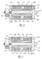
- the passage of the actuator in its second stable state, illustrated in FIG. 4, is obtained by electrically supplying one of the excitation coils 22a and 22b, so that the magnetic flux is oriented in the opposite direction to that created by the permanent magnet 42.
- the flux lines thus generated successively pass through the breastplate 16, the magnetic plate 34, the core 20 and the magnetic plate 36, as illustrated in L2 in FIG. 3.
- the resulting flow present in the air gap "fixed assembly 10 '- magnetic plate 36" is canceled and the flow present in the air gap "fixed assembly 10' - magnetic plate 34" generates an attraction force along the axis 14.
- the plate 34 is thus pressed against the corresponding end of the fixed assembly 10 ', so that the other plate 36 is spaced from the other end of this fixed assembly by the distance d.
- the return of the actuator to its first state illustrated in Figure 2 is obtained by electrically supplying the second coil 22a or 22b in such a way that the magnetic flux is oriented in opposite direction by compared to that generated by the permanent magnet 42.
- the actuator electromagnetic linear acts on the device (s) (not shown) for which it provides the command by the pawn (s) 40 which appear on the right of Figures 1 to 4.
- the electromagnetic linear actuator according to the invention may undergo different modifications by compared to the embodiments described, without going out of the scope of the invention.
- the magnetic plate 36 can be eliminated and replaced by a stop of any kind limiting the spacing between the magnetic plate 34 and the corresponding end of the fixed assembly 10 at a predetermined distance d. From this point of view, it will be observed that the particular structure of the actuator makes it necessary to limit this distance d to a relatively small value.
- one of the two coils excitement can be suppressed.
- the transition from a state stable to the other is then achieved by means of a single coil that is energized with polarities different depending on the desired stable position.
- FIG 5 there is shown an application monostable and bistable actuators that come to be described with reference to Figures 1 to 4, control of the valves of a fluid regulator, designed especially to be placed in two parallel circuits for fueling a satellite engine (not shown), from two tanks (not shown) propellants under pressure.
- the regulator generally designated by the reference 44, includes two sets of identical valves, arranged in parallel inside the same body 46, and only one of which is visible in FIG. 5. Each of these valve assemblies is intended to be mounted in one of the two parallel circuits mentioned above propellant supply.
- Each of these valve assemblies includes a first valve 50 and a second valve 48, mounted in series in this order, inside a passage 52 which crosses the body 46.
- the two ends of each passage 52 are fitted with fittings (not shown) which allow the regulator to be mounted in both fluid circuits mentioned above.
- Valves 48 and 50 are identical. Only one of the second valves 48 will now be described, by means of numerical references assigned the letter a . This description also applies to the first valves 50, replacing the letter a with the letter b .
- Each of the second valves 48 includes a seat valve 54a formed in passage 52 and in the center which opens an upstream section of this passage. Beyond from seat 54a, passage 52 widens to form a chamber 56a, in which is housed a valve 58a of the corresponding valve 48.
- valve 58a of each of the valves 48 is fixed on a rod 60a which forms the end of a lever actuator 62a, articulated in the body 46 of the regulator, by a pivot axis 64a. More precisely, if we designate by reference numeral 66a the axis of the valve seat 54a, axes 64a and 66a are orthogonal between them and, both, substantially perpendicular to the longitudinal axis 68a of the lever 62a.
- the rod 60a carrying the valve 58a projects from a disc-shaped part of the actuating lever 62a, parallel to the longitudinal axis 66a of this lever, crossing a wall with a certain clearance delimiting room 56a.
- a first end of a metal sealing bellows 70a is fixed so watertight on said disc-shaped portion of the lever 62a, and surrounds an adjacent part of this lever.
- the second end of the bellows 70a is fixed to a removable part of the body 46, carrying the pivot axis 64a.
- valve 58a fixed to the end of the lever 62a which actuates it increases the lifespan by avoiding any wear by friction in this place.
- the reliability of tightness is also increased, since no particle linked to friction wear does not risk come to be placed between the valve 58a and its seat 54a.
- valve 58a on the rod 60a is provided by means adjustment adjustment 72a, when the valve 58a and the seat 54a abuts one against the other by flat surfaces, as illustrated on the Figure 5.
- the orientation adjustment means 72a include, for example, a spherical surface formed on rod 60a, trapped between two conical surfaces linked to the valve, and a locking screw or nut.
- these orientation adjustment means can be removed by replacing valve 58a with a ball and giving the valve seat 54a a shape truncated.
- the actuation levers 62a and 62b extend to the outside of the body 46 of the regulator 44, so that be capable of being actuated, respectively, by actuators 74 and 76.
- a single actuator 76 acts on the two levers 62b to control simultaneously the first two valves 50, and an actuator single 74 acts on the two levers 62a to steer simultaneously the two second valves 48.
- the actuator 76 is a bistable actuator conforms to that which was described previously in referring to figures 2 to 4. It allows to order the opening of the first valves 50 throughout the motor supply period. It constitutes besides a safety allowing to close the circuits supply in the event of blockage of the second valves 48 in the open position.
- the actuator 74 is a monostable actuator conforms to that which was described previously in referring to figure 1. It allows to control a beat controlled from the second valves 48 when the supply in propellants of the corresponding engine is desired.
- each of the actuators 74 and 76 is fixed by screws 78 on a corresponding lug of the body 46 of the regulator 44. This fixing is such that the respective axes 80 and 82 of the fixed sets of actuators 74 and 76 are parallel to each other, as well as to axes 66a, 66b of seats of valves 48 and 50, and oriented according to a direction orthogonal to the longitudinal axes 68a, 68b of the actuating levers 62a, 62b.
- the actuator 74 acts simultaneously on the ends of the two levers 62a by two pins 84, preferably of adjustable length.
- a spring compression helical 86, low calibration, is mounted on each of the pins 84, to maintain normally a small clearance between the pawns 84 and the levers 62a, to prevent possible transmission vibrations.
- valves 48 in position closed is secured separately by springs of reminder 88 arranged between the ends of the levers 62a and a case 90 linked to the magnetic outer breastplate actuator 74.
- Return springs 88 are arranged along the axes of the pins 84, and opposite to these with respect to the levers 62a. The taring of these springs 88 is greater than that of springs 86.
- the actuator 76 acts simultaneously on the ends of the two levers 62b in pairs pins 92, preferably of adjustable length, which are kept very slightly away from the levers by compression coil springs 94.
- Compression springs reminder 96 based on a case 98 linked to the actuator 76 magnetic outer breastplate, maintain the valves 50 in the closed position.
- FIG. 5 shows the device in its state rest. Valves 48 and 50 are kept closed by the sole action of springs 88 and 96.
- the actuator bistable 76 When it is necessary to supply propellants with satellite engine powered by across the device of Figure 5, the actuator bistable 76 is brought into its second stable state, this which results in a displacement of the pawns 92 towards the right considering figure 5. We thus command the simultaneous opening of the first two valves 50, via levers 62b. The valves 50 will remain in this state until the power in propellants is discontinued.
- the second valves 48 are piloted so as to beat them in a controlled manner, to bring engine the desired amounts of propellants.
Landscapes
- Engineering & Computer Science (AREA)
- Physics & Mathematics (AREA)
- Electromagnetism (AREA)
- Power Engineering (AREA)
- General Physics & Mathematics (AREA)
- Automation & Control Theory (AREA)
- Chemical & Material Sciences (AREA)
- Combustion & Propulsion (AREA)
- Mechanical Engineering (AREA)
- General Engineering & Computer Science (AREA)
- Magnetically Actuated Valves (AREA)
- Electromagnets (AREA)
Description
- un siège de vanne formé dans un passage traversant un corps fixe, ce siège étant centré sur un deuxième axe parallèle à l'axe de l'ensemble fixe de l'actionneur ;
- un levier d'actionnement monté pivotant dans le corps fixe, autour d'un troisième axe orthogonal au deuxième axe, ce levier étant orienté selon une direction sensiblement perpendiculaire à l'axe de l'ensemble fixe de l'actionneur et aux deuxième et troisième axes ;
- un clapet fixé à une première extrémité du levier d'actionnement, de façon à pouvoir venir en appui étanche sur le siège de vanne dans une position de l'actionneur ;
- un soufflet d'étanchéité disposé autour du levier d'actionnement, relié à ce levier par une première extrémité et relié au corps fixe par une extrémité opposée.
- la figure 1 est une vue en coupe longitudinale partielle qui représente un actionneur linéaire électromagnétique monostable conforme à l'invention, cet actionneur étant illustré dans son état de repos sur la partie supérieure de la figure et dans son état d'actionnement sur la partie inférieure de la figure ;
- la figure 2 est une vue comparable à la figure 1 représentant un actionneur linéaire électromagnétique bistable conforme à l'invention, dans un premier de ses deux états stables ;
- la figure 3 représente l'actionneur de la figure 2, au moment où un changement d'état est commandé ;
- la figure 4 représente l'actionneur de la figure 2 dans son deuxième état stable ; et
- la figure 5 est une vue en coupe partielle qui illustre une application des actionneurs des figures 1 à 4 au pilotage des vannes d'un régulateur de fluides.
Claims (10)
- Actionneur linéaire électromagnétique, comprenant :caractérisé en ce que l'ensemble fixe comprend deux entretoises (24,26 ;24,26') interposées entre la cuirasse extérieure magnétique (16) et le noyau intérieur magnétique (20), de part et d'autre des moyens de commande électromagnétiques (18,18'), et des moyens de fixation démontables (28) reliant mécaniquement le noyau intérieur magnétique (20) et la cuirasse extérieure magnétique (16) en traversant les entretoises, de telle sorte que l'actionneur est formé de pièces mécaniques standard, aptes à être associées à des moyens de commande électromagnétiques (18,18') de différents types.un ensemble fixe (10,10'), de forme annulaire autour d'un axe (14), incluant, de l'extérieur vers l'intérieur, une cuirasse extérieure magnétique (16), des moyens de commande électromagnétiques (18,18') et un noyau intérieur magnétique (20) ; etun ensemble mobile (12) apte à se déplacer selon ledit axe (14) lors d'un actionnement des moyens de commande électromagnétiques (18,18'), cet ensemble mobile incluant au moins un premier plateau magnétique (34) placé en face d'une première extrémité de l'ensemble fixe (10,10') ;
- Actionneur selon la revendication 1, dans lequel l'ensemble mobile (12) comprend un deuxième plateau magnétique (36) placé en face d'une deuxième extrémité de l'ensemble fixe (10, 10') et relié au premier plateau magnétique (34) par une tige (30) traversant l'ensemble fixe de façon à pouvoir coulisser selon ledit axe (14) d'une distance (d) déterminée par la venue en appui de chacun des plateaux (34,36) contre l'extrémité correspondante de l'ensemble fixe (10,10').
- Actionneur selon l'une quelconque des revendications 1 et 2, dans lequel les différents type de moyens de commande électromagnétiques comprennent des moyens de commande monostables (18) et des moyens de commande bistables (18').
- Actionneur selon la revendication 3, dans lequel les moyens de commande monostables (18) comprennent une bobine d'excitation (22) les deux entretoises incluant une entretoise magnétique (26) et une entretoise amagnétique (24), placées de part et d'autre de la bobine d'excitation (22).
- Actionneur selon l'une quelconque des revendications 3 et 4, dans lequel les moyens de commande bistables (18') comprennent un aimant permanent (42) interposé entre deux bobines d'excitation (22a, 22b) les deux entretoises (24, 26') étant amagnétiques et placées de part et d'autre des bobines d'excitation (22a,22b).
- Régulateur de fluides comprenant au moins une vanne (48, 50) pilotée par un actionneur (74, 76) selon l'une quelconque des revendications précédentes, dans lequel la vanne (48, 50) comprend :un siège de vanne (54a, 54b) formé dans un passage (52) traversant un corps fixe (46), ce siège étant centré sur un deuxième axe (66a, 66b) parallèle à l'axe (80, 82) de l'ensemble fixe de l'actionneur ;un levier d'actionnement (62a, 62b) monté pivotant dans le corps fixe (46), autour d'un troisième axe (64a, 64b) orthogonal au deuxième axe (66a, 66b), ce levier étant orienté selon une direction sensiblement perpendiculaire à l'axe (80, 82) de l'ensemble fixe de l'actionneur et aux deuxième et troisième axes ;un clapet (58a, 58b) fixé à une première extrémité du levier d'actionnement (62a, 62b), de façon à pouvoir venir en appui étanche sur le siège de vanne (54a, 54b) dans une position de l'actionneur (74, 76) ;un soufflet d'étanchéité (70a, 70b) disposé autour de levier d'actionnement (62a, 62b) relié à ce levier par une première extrémité et relié au corps fixe (46) par une extrémité opposée.
- Régulateur selon la revendication 6, dans lequel le siège de vanne (54a, 54b) est plan et le clapet (58a, 58b) fixé à la première extrémité du levier d'actionnement (62a, 62b) par des moyens de réglage d'orientation (72a, 72b).
- Régulateur selon la revendication 6, dans lequel le siège de vanne (54a, 54b) est tronconique et le clapet (58a, 58b) sphérique.
- Régulateur selon l'une quelconque des revendications 6 à 8, comprenant au moins une première vanne (50) pilotée par un premier actionneur (76), incluant des moyens de commande électromagnétiques bistables, et au moins une deuxième vanne (48) pilotée par un deuxième actionneur (74) incluant des moyens de commande électromagnétiques monostables, la première et la deuxième vannes (50, 48) étant prévues pour être placées dans cet ordre dans un circuit d'alimentation en fluides.
- Régulateur selon la revendication 9, comprenant deux premières vannes (50) pilotées simultanément par le premier actionneur (76) et deux deuxièmes vannes (48) pilotées simultanément par le deuxième actionneur (74), les premières et deuxèmes vannes (50, 48) étant prévues pour être placées dans cet ordre dans deux circuits parallèles d'alimentation en fluides.
Applications Claiming Priority (3)
| Application Number | Priority Date | Filing Date | Title |
|---|---|---|---|
| FR9511976A FR2739968B1 (fr) | 1995-10-12 | 1995-10-12 | Actionneur lineaire electromagnetique a plateaux mobiles et regulateur de fluides a vannes pilotees par un tel actionneur |
| FR9511976 | 1995-10-12 | ||
| PCT/FR1996/001593 WO1997014160A1 (fr) | 1995-10-12 | 1996-10-11 | Actionneur lineaire electromagnetique a plateaux mobiles et regulateur de fluides a vannes pilotees par un tel actionneur |
Publications (2)
| Publication Number | Publication Date |
|---|---|
| EP0852060A1 EP0852060A1 (fr) | 1998-07-08 |
| EP0852060B1 true EP0852060B1 (fr) | 2004-01-28 |
Family
ID=9483464
Family Applications (1)
| Application Number | Title | Priority Date | Filing Date |
|---|---|---|---|
| EP96934899A Expired - Lifetime EP0852060B1 (fr) | 1995-10-12 | 1996-10-11 | Actionneur lineaire electromagnetique a plateaux mobiles et regulateur de fluides a vannes pilotees par un tel actionneur |
Country Status (6)
| Country | Link |
|---|---|
| US (1) | US5820100A (fr) |
| EP (1) | EP0852060B1 (fr) |
| JP (1) | JPH11513536A (fr) |
| DE (1) | DE69631427T2 (fr) |
| FR (1) | FR2739968B1 (fr) |
| WO (1) | WO1997014160A1 (fr) |
Families Citing this family (3)
| Publication number | Priority date | Publication date | Assignee | Title |
|---|---|---|---|---|
| US6543466B2 (en) * | 2000-03-02 | 2003-04-08 | Rajinder S. Gill | Mass flow controller and method of operation of mass flow controller |
| CN1234135C (zh) * | 2001-01-18 | 2005-12-28 | 株式会社日立制作所 | 电磁铁和使用该电磁铁的开关装置的操作机构 |
| DE102010055481A1 (de) * | 2010-12-22 | 2012-06-28 | Continental Automotive Gmbh | Magnetbaueinheit |
Family Cites Families (11)
| Publication number | Priority date | Publication date | Assignee | Title |
|---|---|---|---|---|
| US1700228A (en) * | 1923-01-30 | 1929-01-29 | Regan Safety Devices Co Inc | Electromagnet |
| US3201661A (en) * | 1963-01-11 | 1965-08-17 | Clary Corp | Rotary solenoid having a rectangular stator member |
| DE1956721A1 (de) * | 1969-11-12 | 1971-05-13 | Hans Nix | Elektromagnetische einstellbare Zug- und Druckfeder |
| GB1309452A (en) * | 1970-06-06 | 1973-03-14 | Wilmot Breeden Ltd | Solenoid actuators |
| US3891952A (en) * | 1971-05-07 | 1975-06-24 | Non Ferrous International Corp | Electromagnetic assembly resisting axial armature movement for working or finning tubing |
| JPS5586983A (en) * | 1978-12-22 | 1980-07-01 | Ricoh Co Ltd | Solenoid valve |
| JPS59154006A (ja) * | 1983-02-22 | 1984-09-03 | Matsushita Electric Works Ltd | 有極型ソレノイド |
| US4994776A (en) * | 1989-07-12 | 1991-02-19 | Babcock, Inc. | Magnetic latching solenoid |
| DE4023828A1 (de) * | 1990-07-27 | 1992-01-30 | Bosch Gmbh Robert | Verfahren zur einstellung eines ventils und ventil |
| US5143118A (en) * | 1991-02-14 | 1992-09-01 | Akos Sule | Solenoid control valve |
| US5314164A (en) * | 1992-07-17 | 1994-05-24 | Mks Instruments, Inc. | Pivotal diaphragm, flow control valve |
-
1995
- 1995-10-12 FR FR9511976A patent/FR2739968B1/fr not_active Expired - Fee Related
-
1996
- 1996-10-11 EP EP96934899A patent/EP0852060B1/fr not_active Expired - Lifetime
- 1996-10-11 US US08/849,244 patent/US5820100A/en not_active Expired - Fee Related
- 1996-10-11 JP JP9514779A patent/JPH11513536A/ja not_active Ceased
- 1996-10-11 DE DE69631427T patent/DE69631427T2/de not_active Expired - Fee Related
- 1996-10-11 WO PCT/FR1996/001593 patent/WO1997014160A1/fr not_active Ceased
Also Published As
| Publication number | Publication date |
|---|---|
| FR2739968B1 (fr) | 1998-01-02 |
| US5820100A (en) | 1998-10-13 |
| WO1997014160A1 (fr) | 1997-04-17 |
| EP0852060A1 (fr) | 1998-07-08 |
| FR2739968A1 (fr) | 1997-04-18 |
| DE69631427T2 (de) | 2004-11-04 |
| DE69631427D1 (de) | 2004-03-04 |
| JPH11513536A (ja) | 1999-11-16 |
Similar Documents
| Publication | Publication Date | Title |
|---|---|---|
| EP0263863B1 (fr) | Soupape ou vanne a haut niveau de fiabilite | |
| EP2531756B2 (fr) | Electrovanne pilote | |
| FR2965683A1 (fr) | Installation electromagnetique et installation d'assistance de conduite equipee d'une telle installation | |
| FR2735187A1 (fr) | Poussoir a actionnement unique motorise par un materiau a memoire de forme. | |
| EP0631075A1 (fr) | Electrovanne à double siège, et circuit de recyclage de vapeurs d'essence comportant un tel clapet | |
| EP4146509B1 (fr) | Actionneur électromagnétique à commande manuelle et valve de frein de stationnement équipée d'un tel actionneur | |
| EP0682615B1 (fr) | Electrovalve pneumatique proportionnelle | |
| FR2739968A1 (fr) | Actionneur lineaire electromagnetique a plateaux mobiles et regulateur de fluides a vannes pilotees par un tel actionneur | |
| EP0419352B1 (fr) | Electrovanne à aimant permanent | |
| EP4244962A1 (fr) | Actionneur electromagnetique bistable et valve de frein d'aeronef equipee d'un tel actionneur | |
| EP1114929A1 (fr) | Dispositif de contrôle d'alimentation en gaz d'un injecteur de gaz | |
| CA2358209A1 (fr) | Actionneur electromagnetique equipe de moyens d'ajustement de la position de son element polaire mobile | |
| EP1751403A1 (fr) | Dispositif d'actionnement de soupapes | |
| EP0752152B1 (fr) | Actionneur magnetique a entrefers multiples | |
| EP0549490A1 (fr) | Electrovanne à noyau mobile plat | |
| FR2559301A1 (fr) | Solenoide a caracteristiques reduites de bruit | |
| WO2002065497A1 (fr) | Dispositif de manoeuvre bistable en translation d'un axe mobile | |
| FR2620786A1 (fr) | Dispositif permettant d'influencer la valeur de retour d'une soupape | |
| FR2793597A1 (fr) | Dispositif de commande de position de type electromagnetique | |
| EP4716807A1 (fr) | Actionneur électromagnétique et système de transmission équipé d'un tel actionneur | |
| FR2616488A1 (fr) | Convertisseur electro-pneumatique a protection anti-deflagrante | |
| WO2007063223A1 (fr) | Actionneur electromagnetique a aimants permanents disposes en v | |
| FR2785031A1 (fr) | Vanne electromagnetique du type a tiroir cylindrique | |
| WO2004088188A2 (fr) | Dispositif d'actionnement electromagnetique | |
| WO2019106076A1 (fr) | Dispositif electromagnetique |
Legal Events
| Date | Code | Title | Description |
|---|---|---|---|
| PUAI | Public reference made under article 153(3) epc to a published international application that has entered the european phase |
Free format text: ORIGINAL CODE: 0009012 |
|
| 17P | Request for examination filed |
Effective date: 19970526 |
|
| AK | Designated contracting states |
Kind code of ref document: A1 Designated state(s): BE DE GB IT |
|
| RAP1 | Party data changed (applicant data changed or rights of an application transferred) |
Owner name: AEROSPATIALE MATRA |
|
| 17Q | First examination report despatched |
Effective date: 20021126 |
|
| GRAH | Despatch of communication of intention to grant a patent |
Free format text: ORIGINAL CODE: EPIDOS IGRA |
|
| GRAS | Grant fee paid |
Free format text: ORIGINAL CODE: EPIDOSNIGR3 |
|
| RAP1 | Party data changed (applicant data changed or rights of an application transferred) |
Owner name: EADS FRANCE |
|
| GRAA | (expected) grant |
Free format text: ORIGINAL CODE: 0009210 |
|
| RAP1 | Party data changed (applicant data changed or rights of an application transferred) |
Owner name: EUROPEAN AERONAUTIC DEFENCE AND SPACE COMPANY - EA |
|
| AK | Designated contracting states |
Kind code of ref document: B1 Designated state(s): BE DE GB IT |
|
| REG | Reference to a national code |
Ref country code: GB Ref legal event code: FG4D Free format text: NOT ENGLISH |
|
| REF | Corresponds to: |
Ref document number: 69631427 Country of ref document: DE Date of ref document: 20040304 Kind code of ref document: P |
|
| GBT | Gb: translation of ep patent filed (gb section 77(6)(a)/1977) |
Effective date: 20040510 |
|
| PLBE | No opposition filed within time limit |
Free format text: ORIGINAL CODE: 0009261 |
|
| STAA | Information on the status of an ep patent application or granted ep patent |
Free format text: STATUS: NO OPPOSITION FILED WITHIN TIME LIMIT |
|
| 26N | No opposition filed |
Effective date: 20041029 |
|
| PGFP | Annual fee paid to national office [announced via postgrant information from national office to epo] |
Ref country code: GB Payment date: 20051005 Year of fee payment: 10 |
|
| PGFP | Annual fee paid to national office [announced via postgrant information from national office to epo] |
Ref country code: DE Payment date: 20051026 Year of fee payment: 10 |
|
| PGFP | Annual fee paid to national office [announced via postgrant information from national office to epo] |
Ref country code: BE Payment date: 20051220 Year of fee payment: 10 |
|
| PGFP | Annual fee paid to national office [announced via postgrant information from national office to epo] |
Ref country code: IT Payment date: 20061031 Year of fee payment: 11 |
|
| PG25 | Lapsed in a contracting state [announced via postgrant information from national office to epo] |
Ref country code: DE Free format text: LAPSE BECAUSE OF NON-PAYMENT OF DUE FEES Effective date: 20070501 |
|
| GBPC | Gb: european patent ceased through non-payment of renewal fee |
Effective date: 20061011 |
|
| PG25 | Lapsed in a contracting state [announced via postgrant information from national office to epo] |
Ref country code: GB Free format text: LAPSE BECAUSE OF NON-PAYMENT OF DUE FEES Effective date: 20061011 |
|
| BERE | Be: lapsed |
Owner name: EUROPEAN AERONAUTIC DEFENCE AND SPACE CY - *EADS F Effective date: 20061031 |
|
| PG25 | Lapsed in a contracting state [announced via postgrant information from national office to epo] |
Ref country code: IT Free format text: LAPSE BECAUSE OF NON-PAYMENT OF DUE FEES Effective date: 20071011 Ref country code: BE Free format text: LAPSE BECAUSE OF FAILURE TO SUBMIT A TRANSLATION OF THE DESCRIPTION OR TO PAY THE FEE WITHIN THE PRESCRIBED TIME-LIMIT Effective date: 20061031 |