EP0852130A2 - Procédé et dispositif pour le fonctionnement et/ou le nettoyage et/ou le traitement du système d'évacuation de déchets fluides d'un poste de traitement médical ou dentaire - Google Patents
Procédé et dispositif pour le fonctionnement et/ou le nettoyage et/ou le traitement du système d'évacuation de déchets fluides d'un poste de traitement médical ou dentaire Download PDFInfo
- Publication number
- EP0852130A2 EP0852130A2 EP98100020A EP98100020A EP0852130A2 EP 0852130 A2 EP0852130 A2 EP 0852130A2 EP 98100020 A EP98100020 A EP 98100020A EP 98100020 A EP98100020 A EP 98100020A EP 0852130 A2 EP0852130 A2 EP 0852130A2
- Authority
- EP
- European Patent Office
- Prior art keywords
- water
- air
- drain line
- collecting container
- valve
- Prior art date
- Legal status (The legal status is an assumption and is not a legal conclusion. Google has not performed a legal analysis and makes no representation as to the accuracy of the status listed.)
- Granted
Links
Images



Classifications
-
- A—HUMAN NECESSITIES
- A61—MEDICAL OR VETERINARY SCIENCE; HYGIENE
- A61C—DENTISTRY; APPARATUS OR METHODS FOR ORAL OR DENTAL HYGIENE
- A61C1/00—Dental machines for boring or cutting ; General features of dental machines or apparatus, e.g. hand-piece design
- A61C1/0061—Air and water supply systems; Valves specially adapted therefor
- A61C1/0076—Sterilising operating fluids or fluid supply elements such as supply lines, filters
-
- A—HUMAN NECESSITIES
- A61—MEDICAL OR VETERINARY SCIENCE; HYGIENE
- A61C—DENTISTRY; APPARATUS OR METHODS FOR ORAL OR DENTAL HYGIENE
- A61C17/00—Devices for cleaning, polishing, rinsing or drying teeth, teeth cavities or prostheses; Saliva removers; Dental appliances for receiving spittle
- A61C17/14—Dental appliances for receiving spittle, with or without rinsing means therefor, e.g. dental basins, spittoons, cuspidors
-
- A—HUMAN NECESSITIES
- A61—MEDICAL OR VETERINARY SCIENCE; HYGIENE
- A61C—DENTISTRY; APPARATUS OR METHODS FOR ORAL OR DENTAL HYGIENE
- A61C17/00—Devices for cleaning, polishing, rinsing or drying teeth, teeth cavities or prostheses; Saliva removers; Dental appliances for receiving spittle
- A61C17/06—Saliva removers; Accessories therefor
- A61C17/065—Saliva removers; Accessories therefor characterised by provisions for processing the collected matter, e.g. for separating solids or air
Definitions
- Contaminations with a large specific weight tend to especially in horizontal or with a slight inclination Pipes to settle on the pipe floor, where they are hinder the flow of excrement.
- organic contaminants such as blood, saliva, tissue residues and the like are breeding grounds for microorganisms that in the Drainage system form vegetation and incrustations, which too Malfunctions in the pipes and / or hoses of the Drainage system and defects in valves, a separator and can lead an amalgam separator of the drain system.
- Other disadvantages are the bad smell and Infection risk for the practice staff who need the necessary Maintenance work. Will regarding the The aforementioned growths and incrustations do not counteracted, then it comes after certain time intervals to a failure of the drainage system and the associated Treatment place for constipation.
- the invention has for its object to find measures with which sedimentation and / or vegetation and Preventing incrustations in the drainage system, or at least can be reduced. This task is due to the characteristics of claims 1 or 11 solved.
- the inventive method and the device is off beneficial for several reasons. Firstly, due to the Flushing the drainage system with the growth of water Preventing or at least obstructing microorganisms Effect instead, causing fouling and crusting be prevented or at least reduced. This is about it is a care process that has a longer lifespan the drainage system and better and easier drainage of the Excrement guaranteed. The advantages also apply to Presence of a collection container and / or one Odor trap in the drain pipes.
- the water and / or air support a forced Cleaning process takes place both in the drain line as well as in an optionally available collecting container and / or odor trap.
- the flow of the rinse water and / or the air acts as a means of transport the excrements and those already in the drainage system Deposits, which are not only transported in a forced manner but also deposits are removed and removed can be.
- Water commonly used at the treatment site e.g. Dish water and indoor air and / or additional water and additional room air can be used.
- the measures according to the invention are suitable for Drain pipe sections that are both strong and little or no slope, as is the case with one Treatment place is given, especially if several Treatment places with a common suction device are connected.
- the invention also improves the operation of the Suction system.
- the water and / or the air continuously or continuously or only in certain functional areas of the drainage system will.
- the invention relates according to claim 25 Drainage system with a shut-off valve that shuts off the Drain line behind the collection container and also for several, to a common one Drainage line section connected treatment places is suitable. Developments of this inventive concept Claim 26 and 27 prevent contamination of the Shut-off valve.
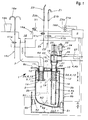
- the main parts of the temporary collecting device 1 or excrement at a treatment place, here a dental treatment center, are a Collection container 2 and / or an odor trap 2.1, one Feed line 3, a discharge line 4 and a balance 5 for the collection container 2 and / or the odor trap 2.1 and an electrical control device S with a Evaluation circuit for the measurement results of the scale 5.
- the Evaluation circuit is in a control unit of the
- the discharge line 4 is with a Connected suction device, which will be described.
- the collecting container 2 can be an odor trap 2.1 act or the odor trap 2.1 can also in the Collection container 2 can be integrated, which is still in the following is described. Therefore if in the further description reference is made to the collecting container 2, then it can always a collection container and / or one Odor trap act because of any odor trap its preferably U-shaped line course one Collector forms or can be designed so large that there is a collection container.
- the collecting container 2 is protected in a housing 6 or Frame arranged.
- This can be a case or Act part of the housing that is specifically for the collection container 2 is provided, or it can also be a housing or Housing part of another component of the treatment center or e.g. a treatment chair.
- the housing 6 of a cuboid shape a bottom wall 6a, upright side walls 6b and one Ceiling wall 6c.
- the scale 5 has a elastic bracket 7, which is approximately vertical
- the direction is elastically effective, so that the collecting container 2 under the effect of its own weight an essentially can perform upright movement, which explains further becomes.
- the movement is preferably approximately vertical guide 8, which according to the embodiments 1 to 6 and 9 can be seen.
- a guide 8 in the sense of a Tilt bearing 8a is provided, in which the collecting container 2 also makes an upright basic movement, but is this is overlaid by a lateral tilting movement.
- the spatial shape of the collecting container 2 can be designed differently be, e.g. round or angular in horizontal cross-section, whereby he a bottom wall 2a, upright side walls 2b and one preferably has horizontal ceiling wall 2c.
- the collecting container 2 is preferably in the area where the discharge line 4 begins in its horizontal Cross-sectional size is tapered by what is symmetrical or asymmetrical, downward converging shape of the bottom wall 2a can be realized.
- the Feed and discharge lines 3, 4 in one and the same Bottom wall 2a or ceiling wall 2c are arranged preferably both lines 3, 4 off-center of the vertical Central axis 9 of the collecting container 2, see e.g. 1 or 7.
- the discharge line 4 possible see e.g. Fig. 6, in the the discharge line 4 is arranged concentrically, e.g. in the ceiling wall 2a.
- the supply and discharge lines 3, 4 enforce the Ceiling walls 2c, 6c each in through holes 2d, 6d, an immobile passage in the ceiling wall 6c is formed, while in the ceiling wall 2c approximately vertically movable cable bushing is realized.
- 1 are in the ceiling wall 6c vertical bushing 11, 12 attached, by which the feed pipe socket 11 to a lesser extent and the one that forms the starting area of the discharge line Drain pipe socket 12 down by a larger amount extends.
- the pipe socket 11, 12 penetrate the ceiling wall 2c of the collecting container 2 in guide holes 13 in the Ceiling wall 2c.
- the pipe sockets 11, 12 Spring abutment 14 provided for two identical springs 15, preferably for the pipe stub 11, 12 surrounding compression coil springs, on the upper ends of the collecting chamber 2 with its ceiling wall 2c rests.
- the arrangement can be made in this way be that the springs 15, the collection chamber 2 with a certain Press the preload against the ceiling wall 6c.
- the guide holes 13 each with a seal a suitable sealing ring. In the present This is done in that between the Ceiling walls 6c and 2c each have a sealing ring 10 or one Sealing plate preferably made of elastically compressible Material arranged and with the ceiling walls 2c, 6c a certain preload is compressed.
- This Bias can be generated in that the springs 15 the Collection container 2 with its ceiling wall 2c against the ceiling wall Preload 6c.
- the seal described last is however effective only when the ceiling walls 2c, 6c are compressed are what only an empty or partially filled one Collection container 2 is the case.
- the sealing rings 10 can the ceiling wall 2c or the ceiling wall 6c.
- a provision device for mouthwash provided consisting of a cup 16b which is in itself is known to be filled with mouthwash.
- This serves a mouthwash line 16c directed into the cup 16b, in which a valve Vla for opening and closing the line 16c is arranged by a control line with the Control device S is connected and can thus be controlled, e.g. taking into account a certain volume that the Cup 16b can be filled without overflowing.
- This can automatically or by actuating one of the treating Doctor and / or a helper actuatable actuator 16d take place, e.g. a switch or a push button that directly can act on the valve Vla or by a signal or Control line can be connected to the control device S.
- the same or similar actuator can also manual opening and closing of the valve V1 can be provided.
- the mouthwash is preferably water or tap water with an appropriate proportion Disinfectant is provided.
- a filling pipe 16e connected to the line 16c at the edge the bowl 16 provided with a vertical Pipe section, the top in the sense of an upside down L or J is bent or angled so far to the side that by manually turning the vertical pipe section Opening of the filling tube 16e either over the cup 16b or is to be positioned over the cuspidor 16.
- a hose is connected to the suction system.
- a dental treatment station can have two suction cups, namely a so-called saliva ejector Z1 and a Spray mist vac Z2 may be provided, each by a Hose Z3, Z4 or the like with the suction system suitable location, e.g. with the Exhaust line 4 behind an existing one Check valve V2.
- Each of these suction cups Z1, Z2 is one for his Function assigned to opening check valve V1b, V1c, the by manual actuation of an actuator Z1a, Z2a is to be opened and closed electrically, the Suction device simultaneously or when lifting the Sucker Z1, Z2 is switched on by a holder Z1b, Z2b.
- the suction cups Z1, Z2 can in all embodiments are provided, however, for reasons of simplification only in Figure 1 shown.
- the check valve V2 In the present embodiment is in the Drain line 4 outside the collecting container 2 and preferably also the check valve V2 outside the housing 6 arranged with a piston rod 18, the line wall penetrates into the discharge line 4 and with a locking piston 19 and an associated valve seat 21 the actual shut-off valve V2 forms.
- the check valve V2 arranged coaxially to the associated pipe socket 12.
- a pneumatic cylinder 22 can drive the valve member serve, by means of a compressed air line 23 from a Compressed air source 24 supplied compressed air can be actuated.
- a directional control valve in the compressed air line 23 25 here in the form of an electromagnetic valve.
- the discharge line 4 Downstream of the valve seat, the discharge line 4 has a Pipe socket 26, here angled pipe socket, of which one Continuation line section 4b to a suction device and other treatment devices for the excrement, e.g. an amalgam separator.
- the upstream of the check valve V2 arranged section of the discharge line is with 4a designated.
- the bowl 16 With increasing inflow of wastewater with excrement the bowl 16 increases the weight of the collecting container 2, so that it sinks against the force of the springs 15. This Movement length is from the elasticity characteristic of the springs dependent. The elasticity of the springs 15 is such that an approximately vertical travel of several centimeters is achieved becomes. When the container 2 reaches its filling level his weight is so great that he is in the lower one End area of the predetermined travel a is located.
- an assigned electrical Switch S1 whose switching signal in the electrical Control device evaluated and an opening signal for the shut-off valve V2 and a switch-on signal for the in Fig. 1st Suction device, not shown, is processed.
- the switch S1 is in the lower End region of the collecting container 2 arranged, whereby it through whose lower end area is operated directly, e.g. if that Filling level N1 is reached.
- the Dirty water collecting container 2 suspended in a spring. He disposes via an opening 6d for the dirty water inlet, the preferably through a hose with the bowl 16 connected is. Furthermore, the collecting container 2 has a Opening 6d for the discharge line 4, e.g. an exhaust pipe, to close and open by the shut-off valve V2 is.
- the collecting container 2 is thus by means of suitable springs 15 held vertically displaceable in its range of motion. Each the position of the collecting container 2 changes according to the degree of filling. If it drops by a certain distance due to the weight, so the switch S1 is actuated, the suction initiated. The valve V2 is opened and one of which downstream suction machine started. Of the The contents of the container are then suctioned off. This will make the Collection container 2 lighter, and it is by the spring force pushed up again. The switch S1 is no longer actuated, thereby closing valve V2.
- the arrangement is such that a liquid residue in the Collection container 2 remains, which is higher at level N2, than the lower end of the suction pipe 12, which is annoying Slurping noises are avoided. If after that Collection container 2 is refilled and thereby due to the growing weight drops down, he finds operation described above again. This then runs oscillating, so fill the reservoir 2, valve V2 trigger, suction, close valve V2, collection container 2 fill etc.
- the suction machine has a run-on time of a few seconds in the oscillating process to ensure continuous suction machine operation.
- a major advantage of the configuration according to the invention is that the existing sensor, namely the respective level N1, N2 determining switch, here the Switch S1, and at least one more too descriptive switch outside the dirt area are arranged and, on the one hand, not susceptible to interference and on the other hand in the clean room area outside the Collecting container 2 are arranged where they are not only are easy to use, but also easier can be installed and removed.
- the system according to the invention therefore works very reliably.
- the valve V2 By arranging the shut-off valve V2 at a high level, here outside the collection container 2 and in particular about the latter and preferably at the upstream end section one laid with a slight slope Exhaust pipe section, the valve V2 is outside the collection area of sedimenting dirty liquid. It is therefore only dynamic during the suction process Dirt particles loaded. There is no risk of Sedimentation. The valve V2 is located thus in an optimal working position.
- Fig. 2 corresponds to one Ready position of device 1, e.g. immediately after a suction process, after which the collection container 2 in its upper position and a minimum level N2 in Collection container 2 is located, the height of which is greater than that Distance b between the pipe socket 12 and the container bottom 2a.
- the odor trap 2.1 is formed.
- a such temporarily or continuously more effective Odor trap can also be formed on the inlet pipe socket 11 be if this is below the level N1 (in Figure 3 indicated) or extends below the level N2. At a such an arrangement will also be noises when entering Excrement or water in the collection container 2 avoided.
- the filling level in the collecting container 2 is reached, so that the switch S1 is operated and simultaneously or successively opened the shut-off valve V2 and the Suction device can be switched on.
- the Collection container 2 suctioned off and emptied. Because of that weight reduction takes place the collecting container 2 pushed up by the spring force of the spring 15. Of the Switch S1 is then no longer actuated, causing the Suction device switched off and the shut-off valve V2 be closed automatically.
- the suction or Emptying amount can be set by a timer or the like are predetermined so that the suction device after their activation a predetermined time runs on and then automatically turns off, causing a certain Filling quantity is emptied.
- the force of the springs 15 and Suction are taking the filling volume into account dimensioned that after switching off the suction in Collection container 2 that the lower edge of the pipe socket 12 somewhat Excess minimum level N2 of the wastewater remains. This prevents annoying slurping noises.
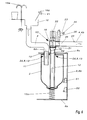
- FIG. 4 shows a special method step, namely a Suction of the collecting container 2 for the purpose of cleaning it, where it is largely or completely emptied and where the Extraction with a higher output and / or intermittent can be done to increase the cleaning effect and a Cleaning or vacuuming the supply and discharge lines 3, 4 to reach.
- This process can be automatic or manual be switched on and carried out, the switch S1 is bridged or a special circuit is used.
- the collecting container 2 preferably sucked completely empty. Because of that weight reduction taking place and by the existing Under pressure, the collecting container 2 is further up moved, pushing against the seal. Doing so if necessary, compressing the seal brought about and the inflow of secondary air, see arrows 32 in Figs. 2 and 3 prevented.
- valves Vlb, Vlc can be closed.
- the shutdown of this process Cleaning suction can also be done by a timer or a certain program progress automatically or manually respectively.
- This cleaning vacuum it is advantageous Rinse water in the feed line 3, what by continuous or intermittent delivery of rinse water by the Flushing water line 16a can take place in the bowl 16, such as it shows Fig. 4 suggestively.
- This control can also can be switched on manually or automatically.
- a cleaning process can be carried out at certain intervals e.g. daily or weekly or before longer ones Downtimes, e.g. at the end of the practice or before the weekend, done manually or automatically.
- FIG. 5 shows a safety device that then comes into operation if a fault, e.g. a Faulty switch S1, no drainage occurred.
- a fault e.g. a Faulty switch S1
- the collecting container 2 sinks due to its increased weight over the switch position for the Switch S1 down.
- a sensor e.g. a second switch S2, the inlet, here the water emitting lines 16a, 16c, to the bowl 16 and stopped the suction device switched on.
- the water or excrement in the Collection container 2 can thus up to the inside of the deeper than the cusp 16 arranged check valve V2 or climb to the discharge line section 27 and through the Shut off the V2 shut-off valve without causing a Water leakage in the area of the collecting tank 2 or in the Area of the bowl 16 comes. It is under the Invention thus possible without such a flushing process Suction of the suction device manually or automatically (program-controlled) in the way of working.
- the aforementioned tilt bearing 8a provided, in which the Collection container 2 a vertical and increasing weight executes a lateral tilting movement at the same time.
- the Collection container 2 is on an approximately horizontal lever arm 35 stored in an end area around a horizontal and lateral pivot axis pivotable in a hinge 36 on Housing 6 mounted and by a spring, in particular Compression spring 15b is biased upwards.
- the feed and Drain lines 3, 4 not on the top but on the Bottom of the collecting container 2 connected.
- the lever arm 35 in vertical holes 37 which is also used to accommodate pipe connections 38 on the underside can serve where the supply and discharge lines 3, 4th can be connected.
- the latter are in the concerned Area preferably formed by flexible hoses.
- Such an odor trap 39 is also in the discharge line 4 in addition to the check valve V2 available, but not in the present embodiment above the ceiling wall 6c but laterally on one associated side wall 6b is arranged, one Housing opening for the passage of the inlet and Drain lines 3, 4 is provided.
- An odor trap 39 in the feed line can also with the rest Embodiments may be provided.
- a corresponding increase in weight of the container 2 in the lateral and preferably upper area of the collecting container 2 arranged switches S1 during a lateral tilting movement of the collecting container 2 released and thereby switched. It is advantageous to switch S1 in the upper area of the Arrange container 2, which makes larger movements of the Collection container are specified.
- the 7 the emptying of the collecting container 2 can also be initiated manually.
- This is in one Side wall 6b of the housing 6 a horizontal plunger 41 in Shape of a pen horizontally displaceable in one Guide hole stored in the side wall 6b and preferably by a compression spring 42 in its outer end position biased.
- the Compression spring 42 between the side wall 6b and one Actuating head of the plunger 41 arranged.
- This configuration also enables manual adjustment the suction device to the special cleaning process Cleaning vacuum.
- the plunger 41 a ventilation hole 44 opposite the side wall arranged by the secondary air 32 in normal suction flows in.
- the ventilation hole 44 is closed so that no secondary air 32 can flow in. This will make the Negative pressure and the flow velocity in the pipes and the collecting container 2 increased and thus an operation Cleaning vacuum switched on, the one with the above Process is comparable.
- the plunger 41 By repeatedly pressing and releasing the plunger 41 can also be a previously described intermittent effect of the cleaning suction can be achieved in which the secondary air 32 is alternately admitted and again is blocked.
- the Sealing plug 45 on the plunger 41 opposite Side wall 6b arranged and attached.
- Tilt bearing 8a can be provided in the sense described above.
- a plunger or Sliding tube 46 approximately corresponding in the tilting direction oblique arrangement provided that in a hole guide 47 in the top wall 6c of the housing 6 is slidably mounted and by a spring 48 pressing against a flange 46a is biased above into a position in which one is at the bottom End or spaced from this end spherical segment-shaped thickening 49 a distance of one Has hole 44a in the ceiling wall 6c, the down pushed state of the slide tube 46, the hole 44a closes.
- a manual attack element e.g. at the Flange 46a attached pressure piece 50 serve.
- This sliding tube 46 which is the lower end portion of the Supply line 3 can form, meets with the plunger 41 comparable purpose.
- the approximately vertical guide 8 through one on the housing 6 attached and surrounding the collecting container 2 guide ring 51a.
- the spring 15 surrounds the collecting container 2 also, is with its lower end on the guide ring 51a supported and with its upper end against a shoulder surface or a support ring 51b on the circumference of the collecting container 2 effective.
- the lower end of the feed line 3 is through one covering the cover walls 2c, 6c and in the Ceiling wall 6c attached pipe socket lla with a flange 11b formed at a lower end, which is the edge of the opening 53 in the ceiling wall 2c with one facing downwards Distance engages when the container 2 is in a is in the upper position. In this position Suction operation secondary air 32 through the opening 53 in the Enter ceiling wall 2c. The opening 53 closes automatically in the functional mode cleaning suction.
- the device 1 for temporarily collecting Excrement at a treatment place one Transport device 55 for transport air 55a is assigned to the an introduction of the transport air into the discharge line 4 optionally for a specific cleaning process for the Drainage line 4 or continuously permitted. This leaves impairment of the discharge for the following reasons the excrement in the discharge line 4 or its Prevent constipation and - if an impairment or Constipation already exists - remove it in a targeted manner.
- the previously described impairment of excrement removal in the discharge line 4 results in particular in one flat laid discharge line 4, which may be Can extend over several meters. Especially in this Drainage area tend to excrement themselves in it to stop transporting water.
- One finds Sedimentation of the heavy parts of the medium to be pumped takes place. Specifically, this means that heavy parts such as metal and Deposit amalagam sanding and with the pipe wall crust. This makes the line wall rough, which too contributes to impairment of the removal.
- the above described deposit processes occur in particular longer downtimes, such as overnight or on Weekend.
- the sedimentation problem described above can be solved by the Prevent feed device 55 for transport air.
- the Feeder 55 includes an inlet opening 56 for Transport air in the discharge line 4, preferably before Area or in the beginning area of horizontal sections the discharge line 4, in which the aforementioned Sedimentation problems occur particularly.
- a advantageous position for the feed device 55 the area directly behind the collection container 2 or, if a check valve V2 is present, directly behind it, as shown in Fig. 10 shows.
- the inlet opening 56 which are located in the upper or ridge area of the discharge line 4 located and by one of the discharge line 4 upwards projecting pipe socket 57 or a transport air supply line may be formed, a check valve 58th assigned that manually or automatically and programmatically can be optionally closed and opened.
- the Piston cylinder 61 can be located under the discharge line 4 be arranged, the piston rod 59 the wall of the Drainage line 4 penetrated sealed from below.
- the Valve seat is labeled 61a.
- the feed device 55 can be switched on, e.g. especially for one Cleaning process of the discharge line 4, to which the Blocking valve V3 opened and one downstream in the Exhaust line 4 arranged suction device be switched on.
- Control device 5 (Fig. 1) is provided.
- the above-described supply device 55 for transport air is particularly suitable for multi-station wet suction 12, in which a plurality of dental treatment places A, B and C each with a treatment chair and with a common suction device 65 are connected in the next a suction machine 66, preferably an amalgam separator 67 and a separator 68 are integrated.
- the Treatment places A, B and C are each with their Exhaust line sections 4b preferably in series with connected to a common discharge line section 4c, which is mainly horizontal or with a slight gradient extends, e.g. laid in the floor or in a building ceiling, is and thus with respect to the above Sedimentation problem is particularly at risk.
- the Check valves V3 can be arranged according to FIG.
- Suction device 65 extends Exhaust pipe section 4d connected to an existing one Sewerage can be connected. It also stretches a discharge pipe section from the suction device 65 4e for separated air.
- an existing treatment station arrangement it can be e.g. a dental practice with one or more, here three Act on treatment places A, B, C.
- the arrangement of the Feeding devices 55 for transport air 55a enables it, by opening selectable or all Feeders 55 one or more particular or all feed line sections 4b including the Leakage pipe section 4c using the effect of Empty transport air 55a. At least one can or all treatment places can be used optionally.
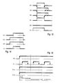
- a Emptying cycle begins when the shut-off valve V1 opens for a time of e.g. about 15 s, i.e. with a Dish bowl rinsing. Afterwards, e.g. after about 5 s preferably simultaneously with the level query at switch S1 the suction machine of the suction device 65 switched on and the Check valves V2, V3 for a time of e.g. open for about 10 s. After closing the shutoff valve V2, the Suction machine and the shutoff valve V3 for a longer one Time t of e.g.
- the check valve V1 approximately at the same time as the shut-off valve V2 or the suction machine can be closed.
- the Drain line sections 4b, 4c during time t however also the collection container 2 and the feed line during the switch-on time of the suction machine is emptied and cleaned, whereby transport air 55a is sucked in and through.
- This Operation can be opened by opening certain or the shutoff valve V3 for one or more or all treatment places A, B, C be performed.
- Fig. 14 is an automatic drain cleaning program schematically represented that manually or automatically, especially before long downtimes, e.g. before the Switch off one or more treatment places A, B, C, and / or at the end of the daily practice or before the weekend can be switched on or put into function.
- the suction machine of the suction device begins to function 65 turned on and the check valve V3 preferably simultaneously for a time of e.g. open for about 20 s. Delayed afterwards, e.g. after about 5 s, the Check valves V1 and V2 e.g. at the same time for a period of e.g. open for about 10 s.
- the Exhaust line sections 4b, 4c but also each Collection container 2 and the feed line 3 forced emptied and cleaned.
- This drain cleaning program can do it alone or additionally provided or in an existing one Control program to be integrated.
- the following describes a procedure for cleaning and / or reducing or avoiding sedimentation in the supply line 3, the collecting container 2 and / or the Odor trap 2.1 and the exhaust line 4 comprehensive Drain pipe is used.
- the Drain pipe at least over part of its length, preferably over its entire length, namely at present dental medical treatment place A, B, C of the bowl 16 starting, rinsed with water.
- the breeding ground for microorganisms impaired or eliminates the growths and incrustations in the drain line form, leading to malfunctions such as blockages in the pipe and hose system as well as defects on valves, on one Can lead separator and / or an amalgam separator. This also causes unpleasant smells and infections reduced or avoided for the practice staff that the necessary maintenance work.
- This cleaning and / or rinsing process is intended in certain Intervals, e.g. between treatments and most of all before long downtimes such as at the end of the practice or before Weekend. It is possible to do this Manual control and actuation appropriate actuators to perform.
- this procedure is a cleaning or care program that is initiated manually or automatically and then automatically expires.
- the automatic introduction can be in realize in an advantageous manner that the cleaning and Care program in the program of a processor-controlled Treatment station A, B, C or treatment device integrated becomes. With an automatic initiation of the cleaning and / or Care program is the operator of one Initiation and, if necessary, implementation of the program completely free.
- FIG. 15 shows the functional sequences of the suction machine of the Suction device 65, the bowl flushing (valve V1), the Spray nebulizer Z2 and the saliva ejector Z1 with each other.
- the Suction machine of suction device 65 switched on and in Leave the function.
- the valve Vlc of the spray mist vacuum cleaner Z2 and / or the valve Vlb of the saliva ejector Z1 can be opened.
- the spray bowl rinse V1 is used in several, e.g. 10 preferably the same Cycles on and off again.
- the cycle time and the Break time can e.g. about 10 seconds. It takes place not just a drain line but also one Cleaning instead.
- the flushing takes place through the flow of the Water, which is - as with the rinsing measures of the above-described embodiments - tap water a normal home supply.
- the Switches S1, S2 are deactivated, so that the Collection container 2 fills completely and sinks and that Water rises to the open shut-off valve V2 and then drains away due to gravity.
- Another source of water is the cup feed into the rinse to be confiscated.
- One is particularly suitable for this Line 16b rotating about its vertical central axis leaves, so that the arched outlet with its opening over the bowl bowl is rotatable and mouthwash after previous opening of the valve Vla in the cuspidor 16 can flow.
- the latter measure is not just that advantageous because a larger amount of water for rinsing can be exploited, but also because that Mouthwash in modern treatment centers with one correspondingly large proportion of disinfectant is provided, which has an additional germ-reducing function during the Flushing in the drain line with it.
Landscapes
- Health & Medical Sciences (AREA)
- Life Sciences & Earth Sciences (AREA)
- Oral & Maxillofacial Surgery (AREA)
- Dentistry (AREA)
- Epidemiology (AREA)
- Animal Behavior & Ethology (AREA)
- General Health & Medical Sciences (AREA)
- Public Health (AREA)
- Veterinary Medicine (AREA)
- Water Supply & Treatment (AREA)
- Engineering & Computer Science (AREA)
- Dental Tools And Instruments Or Auxiliary Dental Instruments (AREA)
- External Artificial Organs (AREA)
- Orthopedics, Nursing, And Contraception (AREA)
Applications Claiming Priority (2)
| Application Number | Priority Date | Filing Date | Title |
|---|---|---|---|
| DE19700120A DE19700120A1 (de) | 1997-01-03 | 1997-01-03 | Verfahren zum Betrieb und/oder Reinigen und/oder Pflegen eines Ablfußsystems für fließfähige Exkremente eines medizinischen oder dentalmedizinischen Behandlungsplatzes und Vorrichtung zur Durchführung des Verfahrens oder ein solches Abflußsystem |
| DE19700120 | 1997-01-03 |
Publications (3)
| Publication Number | Publication Date |
|---|---|
| EP0852130A2 true EP0852130A2 (fr) | 1998-07-08 |
| EP0852130A3 EP0852130A3 (fr) | 2002-06-19 |
| EP0852130B1 EP0852130B1 (fr) | 2006-06-21 |
Family
ID=7816816
Family Applications (1)
| Application Number | Title | Priority Date | Filing Date |
|---|---|---|---|
| EP98100020A Expired - Lifetime EP0852130B1 (fr) | 1997-01-03 | 1998-01-02 | Système d'évacuation de déchets fluides d'un poste de traitement médical ou dentaire |
Country Status (3)
| Country | Link |
|---|---|
| EP (1) | EP0852130B1 (fr) |
| AT (1) | ATE330558T1 (fr) |
| DE (2) | DE19700120A1 (fr) |
Cited By (3)
| Publication number | Priority date | Publication date | Assignee | Title |
|---|---|---|---|---|
| RU2349294C1 (ru) * | 2007-06-19 | 2009-03-20 | Общество С Ограниченной Ответственностью "Малое Научно-Производственное Предприятие "Сатурн" | Способ контроля работы оборудования, электро- и пневмоинструмента для зубоврачебного кресла и система для его реализации |
| RU2479298C1 (ru) * | 2011-09-08 | 2013-04-20 | Олег Анатольевич Буглаев | Система контроля работы электро- и пневмоинструмента стоматологической установки |
| CN118948573A (zh) * | 2024-08-03 | 2024-11-15 | 广东弘科医疗科技有限公司 | 一种牙科综合治疗机 |
Families Citing this family (2)
| Publication number | Priority date | Publication date | Assignee | Title |
|---|---|---|---|---|
| DE10323565B4 (de) * | 2003-05-26 | 2006-10-05 | Atmos Medizintechnik Gmbh & Co. | Gerät zur Spülung eines menschlichen Ohres |
| DE202010014097U1 (de) | 2010-10-08 | 2010-12-30 | Zisser Gmbh | Wasch- und Absaugvorrichtung für die Reinigung und Behandlung von Patienten |
Family Cites Families (5)
| Publication number | Priority date | Publication date | Assignee | Title |
|---|---|---|---|---|
| US3988134A (en) * | 1974-01-28 | 1976-10-26 | Gandrud Stanton D | Dental office system |
| US4580978A (en) * | 1984-02-21 | 1986-04-08 | Vincent Motola | Dental high volume evacuation system |
| SE442829B (sv) * | 1984-06-20 | 1986-02-03 | Scania Dental | Apparat for att separera luft och fasta partiklar fran en vetska |
| US5044953A (en) * | 1989-08-30 | 1991-09-03 | Coltene/Whaledent, Inc. | Dental evacuator disinfectant and flush system |
| DE4205936B4 (de) * | 1992-02-27 | 2005-08-04 | Dürr Dental GmbH & Co. KG | Abscheideeinrichtung |
-
1997
- 1997-01-03 DE DE19700120A patent/DE19700120A1/de not_active Withdrawn
-
1998
- 1998-01-02 DE DE59813604T patent/DE59813604D1/de not_active Expired - Lifetime
- 1998-01-02 EP EP98100020A patent/EP0852130B1/fr not_active Expired - Lifetime
- 1998-01-02 AT AT98100020T patent/ATE330558T1/de active
Cited By (3)
| Publication number | Priority date | Publication date | Assignee | Title |
|---|---|---|---|---|
| RU2349294C1 (ru) * | 2007-06-19 | 2009-03-20 | Общество С Ограниченной Ответственностью "Малое Научно-Производственное Предприятие "Сатурн" | Способ контроля работы оборудования, электро- и пневмоинструмента для зубоврачебного кресла и система для его реализации |
| RU2479298C1 (ru) * | 2011-09-08 | 2013-04-20 | Олег Анатольевич Буглаев | Система контроля работы электро- и пневмоинструмента стоматологической установки |
| CN118948573A (zh) * | 2024-08-03 | 2024-11-15 | 广东弘科医疗科技有限公司 | 一种牙科综合治疗机 |
Also Published As
| Publication number | Publication date |
|---|---|
| DE19700120A1 (de) | 1998-07-09 |
| DE59813604D1 (de) | 2006-08-03 |
| ATE330558T1 (de) | 2006-07-15 |
| EP0852130B1 (fr) | 2006-06-21 |
| EP0852130A3 (fr) | 2002-06-19 |
Similar Documents
| Publication | Publication Date | Title |
|---|---|---|
| DE2929804C2 (de) | Zahnärztliche Absaugeinrichtung | |
| EP2641876B1 (fr) | Dispositif de traitement biologique des eaux usées | |
| CH652297A5 (de) | Verfahren und vorrichtung zum abscheiden von fluessigen und festen bestandteilen aus dem aus dem mund eines patienten kommenden saugmediengemisch. | |
| DE2003565B1 (de) | Verfahren und Vorrichtung zum Entleeren eines Leichtfluessigkeitsabscheiders | |
| EP0852130B1 (fr) | Système d'évacuation de déchets fluides d'un poste de traitement médical ou dentaire | |
| EP0332090B1 (fr) | Appareil pour aspirer et évacuer un liquide contenant des matières nocives notamment de l'eau sale | |
| EP1988846B1 (fr) | Unité de rinçage dentaire | |
| EP0278092B1 (fr) | Méthode et dispositif pour contrôler un courant de gaz | |
| DE2459881B2 (de) | Zahnärztliches Gerät mit einer Absaugvorrichtung | |
| EP2627835A1 (fr) | Urinoir et procédé de remplacement d'une fermeture anti-odeurs d'un urinoir | |
| EP0852129B1 (fr) | Procédé et dispositif pour vider un collecteur de déchets fluides compris dans un poste de traitement médical, en particulier dentaire | |
| BE1029234B1 (de) | Gerät | |
| DE4220230C2 (de) | Verfahren und Vorrichtung zur Abtötung von pathogenen Keimen in sanitären Einrichtungen | |
| DE2232622C3 (de) | Klosettspülvorrichtung mit Umlauf der Reinigungsflüssigkeit | |
| EP1210483A2 (fr) | Suceur de vase | |
| DE102017212734B4 (de) | Einbaugetränkegerät mit Ablaufeinrichtung | |
| EP0406635B1 (fr) | Installation de crachoir dentaire | |
| WO2022029106A1 (fr) | Citerne pour un dispositif sanitaire | |
| EP1614816B1 (fr) | Dispositif de vidange et de trop-plein pour appareils sanitaires | |
| EP3633113B1 (fr) | Dispositif de trop-plein, en particulier pour un poste de lavage dans la zone sanitaire | |
| DE2841235A1 (de) | Wc-einrichtung | |
| EP4187028A1 (fr) | Dispositif de filtration pour un réservoir de chasse d'eau et réservoir de chasse d'eau pour un dispositif sanitaire | |
| CH711100A2 (de) | Vorrichtung zur Reinigung einer Toilette oder eines Pissoirs mit einem Wasserspülkasten. | |
| WO1994008217A1 (fr) | Appareil pour le prelevement d'echantillons de boues et d'eaux usees et procede de prelevement de ces echantillons | |
| EP4527278A1 (fr) | Soupape d'eau sale d'une machine de nettoyage de sol et machine de nettoyage de sol |
Legal Events
| Date | Code | Title | Description |
|---|---|---|---|
| PUAI | Public reference made under article 153(3) epc to a published international application that has entered the european phase |
Free format text: ORIGINAL CODE: 0009012 |
|
| AK | Designated contracting states |
Kind code of ref document: A2 Designated state(s): AT BE CH DE DK ES FI FR GB GR IE IT LI LU MC NL PT SE |
|
| AX | Request for extension of the european patent |
Free format text: AL;LT;LV;MK;RO;SI |
|
| PUAL | Search report despatched |
Free format text: ORIGINAL CODE: 0009013 |
|
| AK | Designated contracting states |
Kind code of ref document: A3 Designated state(s): AT BE CH DE DK ES FI FR GB GR IE IT LI LU MC NL PT SE |
|
| AX | Request for extension of the european patent |
Free format text: AL;LT;LV;MK;RO;SI |
|
| 17P | Request for examination filed |
Effective date: 20021217 |
|
| AKX | Designation fees paid |
Designated state(s): AT DE IT |
|
| RAP1 | Party data changed (applicant data changed or rights of an application transferred) |
Owner name: KALTENBACH & VOIGT GMBH & CO. KG |
|
| 17Q | First examination report despatched |
Effective date: 20050623 |
|
| GRAP | Despatch of communication of intention to grant a patent |
Free format text: ORIGINAL CODE: EPIDOSNIGR1 |
|
| RTI1 | Title (correction) |
Free format text: DRAINAGE SYSTEM OF FLUID WASTE OF A MEDICAL OR DENTAL TREATMENT STATION |
|
| RTI1 | Title (correction) |
Free format text: DRAINAGE SYSTEM OF FLUID WASTE OF A MEDICAL OR DENTAL TREATMENT STATION |
|
| GRAS | Grant fee paid |
Free format text: ORIGINAL CODE: EPIDOSNIGR3 |
|
| GRAA | (expected) grant |
Free format text: ORIGINAL CODE: 0009210 |
|
| RAP1 | Party data changed (applicant data changed or rights of an application transferred) |
Owner name: KALTENBACH & VOIGT GMBH |
|
| AK | Designated contracting states |
Kind code of ref document: B1 Designated state(s): AT DE IT |
|
| PG25 | Lapsed in a contracting state [announced via postgrant information from national office to epo] |
Ref country code: IT Free format text: LAPSE BECAUSE OF FAILURE TO SUBMIT A TRANSLATION OF THE DESCRIPTION OR TO PAY THE FEE WITHIN THE PRESCRIBED TIME-LIMIT;WARNING: LAPSES OF ITALIAN PATENTS WITH EFFECTIVE DATE BEFORE 2007 MAY HAVE OCCURRED AT ANY TIME BEFORE 2007. THE CORRECT EFFECTIVE DATE MAY BE DIFFERENT FROM THE ONE RECORDED. Effective date: 20060621 |
|
| REF | Corresponds to: |
Ref document number: 59813604 Country of ref document: DE Date of ref document: 20060803 Kind code of ref document: P |
|
| PLBE | No opposition filed within time limit |
Free format text: ORIGINAL CODE: 0009261 |
|
| STAA | Information on the status of an ep patent application or granted ep patent |
Free format text: STATUS: NO OPPOSITION FILED WITHIN TIME LIMIT |
|
| 26N | No opposition filed |
Effective date: 20070322 |
|
| PGFP | Annual fee paid to national office [announced via postgrant information from national office to epo] |
Ref country code: DE Payment date: 20120207 Year of fee payment: 15 |
|
| PGFP | Annual fee paid to national office [announced via postgrant information from national office to epo] |
Ref country code: IT Payment date: 20120119 Year of fee payment: 15 |
|
| PGFP | Annual fee paid to national office [announced via postgrant information from national office to epo] |
Ref country code: AT Payment date: 20120123 Year of fee payment: 15 |
|
| REG | Reference to a national code |
Ref country code: AT Ref legal event code: MM01 Ref document number: 330558 Country of ref document: AT Kind code of ref document: T Effective date: 20130131 |
|
| PG25 | Lapsed in a contracting state [announced via postgrant information from national office to epo] |
Ref country code: DE Free format text: LAPSE BECAUSE OF NON-PAYMENT OF DUE FEES Effective date: 20130801 Ref country code: AT Free format text: LAPSE BECAUSE OF NON-PAYMENT OF DUE FEES Effective date: 20130131 |
|
| REG | Reference to a national code |
Ref country code: DE Ref legal event code: R119 Ref document number: 59813604 Country of ref document: DE Effective date: 20130801 |
|
| PG25 | Lapsed in a contracting state [announced via postgrant information from national office to epo] |
Ref country code: IT Free format text: LAPSE BECAUSE OF NON-PAYMENT OF DUE FEES Effective date: 20140102 |