EP0852152B1 - Injektionsvorrichtung für medizinische Flüssigkeiten - Google Patents
Injektionsvorrichtung für medizinische Flüssigkeiten Download PDFInfo
- Publication number
- EP0852152B1 EP0852152B1 EP97410144A EP97410144A EP0852152B1 EP 0852152 B1 EP0852152 B1 EP 0852152B1 EP 97410144 A EP97410144 A EP 97410144A EP 97410144 A EP97410144 A EP 97410144A EP 0852152 B1 EP0852152 B1 EP 0852152B1
- Authority
- EP
- European Patent Office
- Prior art keywords
- enclosure
- intended
- deformable
- liquid
- flexible pouch
- Prior art date
- Legal status (The legal status is an assumption and is not a legal conclusion. Google has not performed a legal analysis and makes no representation as to the accuracy of the status listed.)
- Expired - Lifetime
Links
- 239000007788 liquid Substances 0.000 title claims description 49
- 238000002347 injection Methods 0.000 title claims description 35
- 239000007924 injection Substances 0.000 title claims description 35
- 230000000295 complement effect Effects 0.000 claims description 12
- 238000011144 upstream manufacturing Methods 0.000 claims description 12
- 230000002093 peripheral effect Effects 0.000 claims description 10
- 238000000034 method Methods 0.000 claims description 6
- 238000007493 shaping process Methods 0.000 claims description 6
- 239000012530 fluid Substances 0.000 claims description 5
- 238000001990 intravenous administration Methods 0.000 claims description 5
- 208000031968 Cadaver Diseases 0.000 description 6
- 239000000463 material Substances 0.000 description 4
- 238000007789 sealing Methods 0.000 description 4
- 238000011109 contamination Methods 0.000 description 3
- 239000002872 contrast media Substances 0.000 description 3
- 239000012528 membrane Substances 0.000 description 3
- PEDCQBHIVMGVHV-UHFFFAOYSA-N Glycerine Chemical compound OCC(O)CO PEDCQBHIVMGVHV-UHFFFAOYSA-N 0.000 description 2
- 229910000831 Steel Inorganic materials 0.000 description 2
- 229910052782 aluminium Inorganic materials 0.000 description 2
- XAGFODPZIPBFFR-UHFFFAOYSA-N aluminium Chemical compound [Al] XAGFODPZIPBFFR-UHFFFAOYSA-N 0.000 description 2
- 238000002583 angiography Methods 0.000 description 2
- 229940039231 contrast media Drugs 0.000 description 2
- 238000011161 development Methods 0.000 description 2
- 230000018109 developmental process Effects 0.000 description 2
- 238000009434 installation Methods 0.000 description 2
- 238000012544 monitoring process Methods 0.000 description 2
- 210000000056 organ Anatomy 0.000 description 2
- 230000008569 process Effects 0.000 description 2
- 239000010959 steel Substances 0.000 description 2
- 208000030507 AIDS Diseases 0.000 description 1
- 208000005189 Embolism Diseases 0.000 description 1
- 208000007536 Thrombosis Diseases 0.000 description 1
- 238000004458 analytical method Methods 0.000 description 1
- 210000001367 artery Anatomy 0.000 description 1
- 239000011324 bead Substances 0.000 description 1
- 239000008280 blood Substances 0.000 description 1
- 210000004369 blood Anatomy 0.000 description 1
- 230000006835 compression Effects 0.000 description 1
- 238000007906 compression Methods 0.000 description 1
- 238000010276 construction Methods 0.000 description 1
- 238000013461 design Methods 0.000 description 1
- 238000010586 diagram Methods 0.000 description 1
- 230000001079 digestive effect Effects 0.000 description 1
- 201000010099 disease Diseases 0.000 description 1
- 208000037265 diseases, disorders, signs and symptoms Diseases 0.000 description 1
- 229920001971 elastomer Polymers 0.000 description 1
- 239000000806 elastomer Substances 0.000 description 1
- 229920002457 flexible plastic Polymers 0.000 description 1
- -1 for example Substances 0.000 description 1
- 235000011187 glycerol Nutrition 0.000 description 1
- 230000036541 health Effects 0.000 description 1
- 230000006872 improvement Effects 0.000 description 1
- 238000001802 infusion Methods 0.000 description 1
- 238000003780 insertion Methods 0.000 description 1
- 230000037431 insertion Effects 0.000 description 1
- 229920000126 latex Polymers 0.000 description 1
- 239000004816 latex Substances 0.000 description 1
- 229910052751 metal Inorganic materials 0.000 description 1
- 239000002184 metal Substances 0.000 description 1
- 239000000203 mixture Substances 0.000 description 1
- 230000035764 nutrition Effects 0.000 description 1
- 235000016709 nutrition Nutrition 0.000 description 1
- 239000003605 opacifier Substances 0.000 description 1
- 238000004806 packaging method and process Methods 0.000 description 1
- 229920003023 plastic Polymers 0.000 description 1
- 239000004033 plastic Substances 0.000 description 1
- 229920001084 poly(chloroprene) Polymers 0.000 description 1
- 229920001296 polysiloxane Polymers 0.000 description 1
- 238000002360 preparation method Methods 0.000 description 1
- 230000001681 protective effect Effects 0.000 description 1
- 230000000717 retained effect Effects 0.000 description 1
- 229910001220 stainless steel Inorganic materials 0.000 description 1
- 239000010935 stainless steel Substances 0.000 description 1
- 210000003462 vein Anatomy 0.000 description 1
- XLYOFNOQVPJJNP-UHFFFAOYSA-N water Substances O XLYOFNOQVPJJNP-UHFFFAOYSA-N 0.000 description 1
- 238000003466 welding Methods 0.000 description 1
Images


Classifications
-
- A—HUMAN NECESSITIES
- A61—MEDICAL OR VETERINARY SCIENCE; HYGIENE
- A61M—DEVICES FOR INTRODUCING MEDIA INTO, OR ONTO, THE BODY; DEVICES FOR TRANSDUCING BODY MEDIA OR FOR TAKING MEDIA FROM THE BODY; DEVICES FOR PRODUCING OR ENDING SLEEP OR STUPOR
- A61M5/00—Devices for bringing media into the body in a subcutaneous, intra-vascular or intramuscular way; Accessories therefor, e.g. filling or cleaning devices, arm-rests
- A61M5/14—Infusion devices, e.g. infusing by gravity; Blood infusion; Accessories therefor
- A61M5/142—Pressure infusion, e.g. using pumps
- A61M5/145—Pressure infusion, e.g. using pumps using pressurised reservoirs, e.g. pressurised by means of pistons
- A61M5/155—Pressure infusion, e.g. using pumps using pressurised reservoirs, e.g. pressurised by means of pistons pressurised by gas introduced into the reservoir
-
- A—HUMAN NECESSITIES
- A61—MEDICAL OR VETERINARY SCIENCE; HYGIENE
- A61M—DEVICES FOR INTRODUCING MEDIA INTO, OR ONTO, THE BODY; DEVICES FOR TRANSDUCING BODY MEDIA OR FOR TAKING MEDIA FROM THE BODY; DEVICES FOR PRODUCING OR ENDING SLEEP OR STUPOR
- A61M5/00—Devices for bringing media into the body in a subcutaneous, intra-vascular or intramuscular way; Accessories therefor, e.g. filling or cleaning devices, arm-rests
- A61M5/14—Infusion devices, e.g. infusing by gravity; Blood infusion; Accessories therefor
- A61M5/142—Pressure infusion, e.g. using pumps
- A61M5/145—Pressure infusion, e.g. using pumps using pressurised reservoirs, e.g. pressurised by means of pistons
- A61M5/148—Pressure infusion, e.g. using pumps using pressurised reservoirs, e.g. pressurised by means of pistons flexible, e.g. independent bags
- A61M5/1483—Pressure infusion, e.g. using pumps using pressurised reservoirs, e.g. pressurised by means of pistons flexible, e.g. independent bags using flexible bags externally pressurised by fluid pressure
- A61M5/1486—Pressure infusion, e.g. using pumps using pressurised reservoirs, e.g. pressurised by means of pistons flexible, e.g. independent bags using flexible bags externally pressurised by fluid pressure the bags being substantially completely surrounded by fluid
Definitions
- the present invention relates to a device for injecting a medical liquid intended for the human or animal body. He is more particularly relating to an improvement making it possible to pressure the medical liquid to be injected when it is contained in a flexible envelope.
- injectors that include syringes containing the liquid to be injected, the injection head of which is connected to a hypodermic or intravenous needle or catheter through through a pipeline which possibly includes a threshold check valve.
- the preparation of current syringes is done by filling and bubble removal from bottles of different capacities such as 60, 100, 200 milliliters, or even more, such as, for example, 500 milliliters.
- bottles of different capacities such as 60, 100, 200 milliliters, or even more, such as, for example, 500 milliliters.
- the present invention therefore proposes a new simple device, easy to use, reliable and precise.
- the housing body is consisting of a bottom end wall and a wall peripheral formed by at least two lateral wall portions of curved shape
- said portions of side walls each have a cross-section in the form of a portion substantially of a circle, said portions of circles being non concentric and of identical radius.
- said radius of the cross section of the wall portions lateral is constant along the longitudinal axis of the housing body.
- the housing includes a deformable enclosure disposed inside the enclosure of the housing body.
- said enclosure deformable can be formed of two flexible planar walls extended upwards by a divergent wall.
- the device also comprises positioning means intended to allow the positioning of the deformable enclosure substantially in the longitudinal plane of symmetry of the housing.
- the device includes means for setting shape of the deformable enclosure intended to allow said enclosure to substantially take the form of a flexible pouch filled before the introduction of the flexible pouch
- said shaping means may be constituted by a guide grid arranged around the deformable enclosure so as to position the deformable enclosure and put it in a shape substantially identical to that of the pocket flexible.
- the means shutter have a through hole for connecting the flexible bag to the pipe, said sealing means being able to be formed by a cover made up of two complementary parts movable relative to each other.
- the plane of symmetry general longitudinal of the housing is arranged substantially vertically, the upper opening of the housing body being directed upwards so as to allow the evacuation of any bubbles retained in the poached.
- the device of the invention makes it possible to be able to use any type and any size of flexible pouch, both those of 50 milliliters and that of 500 milliliters.
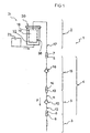
- FIG. 1 schematically illustrates the device injection according to a preferred embodiment of the invention which bears the global reference (1).
- said device includes a proper injector or device supply (2) connected to an injection conduit (3) such as a catheter, a hypodermic or intravenous needle via a pipe (4) made up of several elements.
- Said pipeline (4) includes, at its ends, two branch fittings, one fitting upstream (5) and a downstream connection (6).
- the upstream connection (5) is intended to be connected to a supply connection (7) integral with the injector, while that the downstream connection (6) is intended to be connected to the upstream connection (8) of the injection pipe (3).
- the pipeline (4) includes a safety device (9) as described in the request n ° 93 12590 and which consists of a removable connector comprising a threshold check valve (10) between a upstream pipe (11) and a downstream pipe (12).
- the non-return valve with threshold (10) is adapted to authorize the passage of the upstream liquid in downstream as represented by the arrow "F" when a determined pressure flowing fluid is reached, while it blocks the passage medical fluid in the opposite direction, i.e., from downstream to upstream, i.e. in the opposite direction to that illustrated by the arrow "F".
- the upstream pipe (11) of the safety device (9) comprises a upstream connection (13) intended to be connected to a downstream connection (14) of a upstream portion of the pipeline (4) which also includes another threshold check valve (16), while the downstream pipe (12) includes the downstream connector (6) previously described.
- the pipe (4) is connected to the injector (2) by connection of the upstream connection (5) of said pipe to the connection supply (7).
- said fitting (7) is directly attached to the end of the supply duct (17) of a flexible bag (18) containing the medical liquid (19) to be injected.
- Said flexible pocket (18) being disposed in a housing for pressure (20) of a pressurizing device (21) of the injector (2).
- the pressurization of the flexible bag is carried out by an inert motor liquid enveloping said pocket.
- Said engine fluid inert (22) being contained in the housing (20), and its pressurization being produced by pressurizing means (23) such as a pump high pressure or a cylinder comprising a sliding piston actuated by an electric motor whose advance is controlled, or any other device motorized or even manual.
- pressurizing means (23) such as a pump high pressure or a cylinder comprising a sliding piston actuated by an electric motor whose advance is controlled, or any other device motorized or even manual.
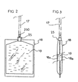
- FIGS 2 and 3 schematically illustrate a pocket (18) such used by the injection device and containing the liquid medical (19) to be injected.
- Said pocket (18) is constituted by the assembly of two sheets of flexible plastic material, a first sheet (18a) and a second identical sheet (18b) associated peripherally by bonding or welding so as to constitute an internal volume (18c) intended to contain the medical liquid (19).
- the lower part of the pocket includes a drain tube (25) provisionally closed by a membrane (250) which is drilled when said tube is connected to the supply duct (17).
- the pocket (18) could include are supply line (17) as shown in lines mixed.
- the pouch thus produced and containing the liquid is soft and deformable and is, according to the invention, placed in the motor liquid (22) of a case (20), said liquid enveloping the entire pocket and being pressurized to deform said pocket homogeneously and device, in order to force the medical liquid to flow into the pipeline (4).
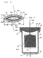
- the housing (20) illustrated Figures 4 to 7 is constituted by a housing body (30) plan longitudinal of general symmetry (P) composed of an end wall lower (31) and a lateral peripheral wall (32) forming a internal enclosure (33) intended to contain the inert motor liquid (22).
- Said housing body (30) has a connection orifice (34) for connecting the pressurizing means (23) of the injection device (1) with the engine liquid (22) contained in the internal enclosure (33), said connection orifice being advantageously located in the lower end wall (31) and being advantageously provided with a cylindrical wall extension (35) threaded extending outward (EXT) to facilitate said connection.
- the connection means between the housing body (30), more particularly said extension (35), and the means for setting pressure (23) can be of any known type.
- the housing body (30) has at its upper end (30a) an upper opening (36) intended to allow the introduction of the flexible bag (18) containing the medical liquid (19) in the enclosure internal (33) of the housing (20).
- means are provided closing (MO) the opening (36) of the housing body (30), said shutter means (MO) being movable between an open position intended to allow the introduction of the flexible pocket inside the enclosure (33) and a closed position allowing the closure of said enclosure.
- Said sealing means (MO) comprise advantageously a passage orifice (37) intended to allow the passage of the supply duct (17) and / or a portion of the tube flow (25) so as to allow the pocket to be connected flexible (18) to the pipe (4) when said pocket is disposed at the interior (INT) of the internal enclosure (33) of the housing (20), as the shows figure 5.
- the lateral peripheral wall (32) of the body of housing (30) has, in a transverse plane (H) perpendicular to the plane of symmetry (P), an elongated cross section of oval shape or ovoid.
- Said peripheral wall is formed, according to the mode of preferred embodiment, by two lateral wall portions (32a, 32b) of curved shape, advantageously curved towards the outside of the enclosure, their respective section in the transverse plane (H) being advantageously each formed by a portion of a circle, said portions of circles being non-concentric and of identical radius "R", as illustrated in figure 6.
- the radius "R" is advantageously between 10 and 18 cm and can be chosen substantially equal to 14 cm.
- the side wall portions (32a, 32b) are arranged symmetrically on either side of the longitudinal plane (P) and are by example connected to each other by two longitudinal weld seams (32c, 32d) as shown in Figures 5 and 6, said weld beads can constitute two curved wall portions whose radius of curvature in the transverse plane (H) is small.
- the body of housing (30) thus has an oblong cross section curved laterally whose shape and dimensions are substantially constants along the longitudinal axis (ZZ ') of the housing. It goes without saying that dimensions of said cross section such as, for example, the radius "R" of the lateral peripheral walls (32a, 32b) could vary longitudinally along the axis (ZZ ') without leaving the field of protection of the invention.
- the elongated oval shape of the section transverse of the housing body (30) allows the distance "d" between the peripheral wall portions (32a, 32b) of said body and the walls (18a, 18b) of said pocket to be substantially constant in a plane transverse as shown in Figure 6.
- an enclosure deformable (38) intended to receive the flexible pocket (18) extends to the interior (INT) of the internal enclosure (33) from the upper opening (36) located at the upper end (30a) of the housing body (30).
- said deformable enclosure is hermetically fixed substantially at the level of the upper opening (36) inside the internal enclosure (33) by fixing means (MF) so as to be arranged and able thus accommodate the flexible pocket (18) inside said enclosure internal (33) without it being in direct contact with the liquid internal motor (22).
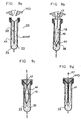
- the deformable enclosure (38) illustrated in FIGS. 8a to 8d is advantageously constituted by two flexible deformable walls (39a, 39b) whose lateral and lower edges are hermetically secured and which is extended upwards in its upper part by a wall divergent (80) whose upper edges (81) are intended to be fixed hermetically by the fixing means (MF) on the periphery of the upper opening (36) thus allowing introduction into said deformable enclosure of the flexible pocket.
- the divergent wall (80) is formed by a surface defined substantially by a straight portion (D) forming a substantially constant angle (I) with a vertical plane substantially equal to 45 ° and traversing the curve contained in the plane transverse (H) corresponding to the curve of elongated oval shape or ovoid of the lateral peripheral wall (32) in said plane located at level of the upper opening (36) as illustrated in FIG. 8d.
- the shape of the divergent wall (80) can be rounded in its lower part according to the longitudinal plane (P) as shown in Figure 8c.
- the fixing means (MF) are advantageously constituted by a member complementary fixing (40) intended to cooperate with a flange upper (41) of the housing body (30) projecting outwards (EXT) said body in a transverse plane (H1) situated substantially at the level of the upper opening (36) so as to wedge the edges upper (81) of the divergent wall (80) of the flexible walls (39a, 39b) constituting the deformable enclosure (38) between said member and the flange in the transverse plane (H1), said divergent wall (80) thus forming a seal.
- the complementary member (40) is fixed against the flange (41) using screws (42) or rivets, for example.
- the enclosure deformable (38) is made of a flexible and deformable material such than Latex, Neoprene, silicone or polydimethyl elastomer.
- the injection device (1) may include means for positioning, not shown, of the deformable enclosure (38) of so that said enclosure extends substantially in the plane (P) in order to be able to hold the flexible pocket (18) in said plane (P).
- said positioning means are constituted by a metal rod integral with the lower edge (43) of the deformable enclosure, said rod being held in the plane P by rigid connecting means connecting it to the lower end wall, by example, or by semi-rigid connecting means allowing it a low longitudinal travel.
- the device (1) includes means for shaping (MMF) of said enclosure intended to allow said deformable enclosure (38) to take a shape substantially approaching the shape of a flexible pocket filled.
- Said shaping means (MMF) are constituted, by example, by a guide grid or a rigid grid (44), the shape corresponds to that of a flexible pouch (18) filled intended to be used in the device (1), said grid (44) being arranged around the deformable enclosure (38).
- the means of shaping (MMF) are intended to allow the flexible walls (39a, 39b) forming the enclosure deformable (38) to move away from each other so as to come against the walls of the guide grid (44) thus giving the user access ease with the enclosure (38). This having therefore taken substantially the shape of a filled flexible pouch, introduction into the enclosure deformable (38) of the pocket (19) is easily carried out.
- formatting means (MMF) could be replaced by a equivalent system without leaving the protective field of the invention.
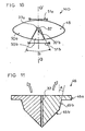
- the means shutter (MO) of the internal enclosure (33) are constituted by a removable cap or cover (46) illustrated particularly in FIGS. 10 and 11.
- Said cover (46) is constituted by an upper plate (46a) whose shape and dimensions are advantageously identical to contour of the upper face of the complementary fixing member (40).
- the upper plate (46a) is extended downwards by a volume (46b) whose section in a transverse plane located near the upper opening (36) has an elongated oval or ovoid shape complementary to that of the internal face of the peripheral wall lateral (32) up to clearance in said plane in order to be able to seal hermetically the internal enclosure (33).
- the part bottom of the plug (46b) has substantially a formed shape by the route along the elongated oval or ovoid curve forming the cross section of the lateral peripheral wall in a horizontal plane located at the upper opening (36), of a right portion oriented substantially at 45 °.
- the upper opening (36) and the volume (46b) of the plug can cooperate thanks to a chamfer inlet (49a) of the upper opening (36) and to a chamfer complementary (49b) of the cap whose inclination A can advantageously be chosen substantially equal to 15 °, as illustrated figure 11.
- the flared shape of the lower part (46b) of the cap is intended to cooperate in a close and complementary way with the particular shape of the divergent wall (80) of the enclosure deformable. This type of arrangement allows perfect compatibility between the opening and closing operations.
- the passage orifice (37) of the sealing means (MO) is advantageously constituted by a passage channel located at center of the plug (46) along the longitudinal axis (ZZ ').
- said plug is made up of two parts (50a, 50b) complementary, said parts being made so that the passage channel (37) is constituted by two grooves (37a, 37b) each located on one of the parts of the plug (50a, 50b). Therefore, said parts are made so as to allow the placement of the supply duct (17) and / or a portion of the tube flow (25) in one of the grooves (37a, 37b) when the two parts (50a, 50b) are separated.
- part (50b) is a centered sector on the axis (ZZ ') of angle B between 10 ° and 90 °, for example.
- Both parts (50a, 50b) are advantageously articulated each in pivoting relative to the housing body (30) by two type joints hinge (51a, 51b) illustrated schematically in Figure 10, between the opening position of the plug (46) and the closed position of the enclosure.
- Locking means (not illustrated) of the cover (46) on the housing body (30) are provided in order to be able to allow the setting pressure of the inert motor liquid (22) inside the enclosure (33), when said cover hermetically seals the opening (36) of the enclosure (33).
- the housing body (30) can advantageously be made of aluminum or steel, for example, so as to be able to put the engine liquid at maximum pressure between 80 and 100 bars
- the inert working liquid (22) can, by for example, be water, glycerin, or a mixture of both.
- the housing (20) is oriented so that the flow orifice of said pocket connected to the pipe opens along the longitudinal axis (ZZ ') upwards (HA), the upper opening (36) of the housing body (30) being located at the upper end of said body.
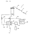
- the enclosure (33) is supplied with motor liquid (22) by a inlet duct (60) connected to a pipe (61), said pipe comprising an electric main valve (62) connected to a jack (63) the piston (64) of which is controlled by a motor to move electric (65) whose advance is controlled by an automation (66).
- the chamber (67) of the cylinder (68) of the jack (63) is connected to an additional reservoir of engine liquid (69) by a secondary conduit (70) and may include a secondary valve electric (71), as shown in figure 12.
- the injection process then includes an introduction step of the flexible pocket in the device formed by the housing (20) as the shows Figures 9a and 9b.
- the setting device pressure (21) causes by removing from the enclosure (33) part of the motor liquid (22) which it contains, a depression in said enclosure. Therefore, the flexible walls (39a, 39b) of the deformable enclosure take the form of a flexible pocket filled with the means of placing shaped (MMF) formed by the guide grid (44).
- the flexible pocket (18) is then introduced into the deformable enclosure (38) taking care positioning or passing the supply channel (17) in the passage orifice (37) of the closure means (MO) such as the shows Figure 9b, said shutter means then being positioned in the closed position.
- the injection step proper illustrated in FIG. 9c consists by means of pressurizing means (23) to reintroduce liquid motor (22) inside the enclosure (33) in order to obtain pressure chosen inside said enclosure so as to cause the deformation of the flexible pocket (18).
- This deformation thus causes the flow of medical liquid (19) in the pipe (4) by through the feed channel (17).
- the flexible bag is vacuum as shown in Figure 9d, the injection is complete and the engine liquid pressure inside the enclosure (33) can be stopped in order to allow the opening of the shutter means (MO) to replace the empty soft bag with a full soft bag repeating the process previously described.
- the management of the various possible valves or organs intended to manage the flows can be automatic, semi-automatic or manual.
- the variations in volume and flow are constantly monitored to ensure precise and safe injection.
- the device comprises a support which can be mobile or fixed and which can be supported on the ground or suspended on a gantry or fixed on the ceiling or on a wall, said support may also include a control and monitoring panel.
- the body of the case could have any form of oval or ovoid cross section elongated so that the width (L1) is greater than the thickness (E1).
- the case can be made in any material such as, for example, steel such as stainless steel, aluminum, or plastic. Add that said case can be made from a cylindrical tube that would be flattened by deformation.
- means may be provided for retaining the part low of the deformable enclosure so as to prevent it from going up accidentally.
- the size of the case could be different, so to be able to contain several bags of medical liquid for injection which would be joined to each other in the enclosure.
- materials used to make the components of the device injection such as the housing, for example, can advantageously present a non-magnetic character so as not to disturb examinations of the type of those using magnetic resonance.
Landscapes
- Health & Medical Sciences (AREA)
- Vascular Medicine (AREA)
- Engineering & Computer Science (AREA)
- Anesthesiology (AREA)
- Biomedical Technology (AREA)
- Heart & Thoracic Surgery (AREA)
- Hematology (AREA)
- Life Sciences & Earth Sciences (AREA)
- Animal Behavior & Ethology (AREA)
- General Health & Medical Sciences (AREA)
- Public Health (AREA)
- Veterinary Medicine (AREA)
- Physics & Mathematics (AREA)
- Fluid Mechanics (AREA)
- Infusion, Injection, And Reservoir Apparatuses (AREA)
Claims (11)
- Vorrichtung zur Durchführung eines Injektionsverfahrens einer medizinischen Flüssigkeit, das darin bestehtdadurch gekennzeichnet, dass das Gehäuse (20) eine verformbare Kammer (38) umfasst, in welcher der flexible Beutel (18), der sich von der oberen, am oberen Ende (30a) des Gehäusekörpers (30) vorgesehenen Öffnung in das Innere (INT) der Innenkammer (33) erstreckt, aufnehmbar ist, während die Kammer aus zwei flexiblen, verformbaren Wandungen (39a, 39b) besteht, deren seitliche und untere Ränder hermetisch miteinander verbunden sind, wobei der Gehäusekörper einen länglichen, ovalen oder ovoiden Querschnitt aufweist.einen flexiblen Beutel (18) zu verwenden, der die zu injizierende medizinische Flüssigkeit (19) enthält, wobei der Beutel dicht ist und mindestens eine Abflussöffnung aufweist, die an ein mit einem Injektionsrohr (3), beispielsweise einem Katheter oder einer hypodermischen, einer intravenösen oder einer anderen Nadel, verbundenen Leitungssystem (4) anschließbar ist,den flexiblen Beutel (18) über eine unter Druck gesetzte inerte Antriebsflüssigkeit (22) so zu verformen, dass der Druck auf die zu injizierende medizinische Flüssigkeit übertragen wird, wodurch diese dazu gezwungen wird, in das Leitungssystem (4) zu fließen, in dem er in die Innenkammer (33) eines die inerte Antriebsflüssigkeit (22) enthaltenden Gehäuses (20) eingesetzt wird, diese Antriebsflüssigkeit dann mit Druck beaufschlagt wird, wobei die Vorrichtung ein Gehäuse (20) mit einer Längssymmetrieebene (P) umfasst, das aus einem Gehäusekörper (30) besteht, welcher eine am oberen Ende (30a) des Körpers vorgesehene obere Öffnung (36) sowie Verschlussmittel (MO) umfasst, die zwischen einer Öffnungsposition zum Einführen des flexiblen Beutels (18) und einer Verschlussposition zum Schließen der Kammer beweglich sind,
- Vorrichtung nach Anspruch 1, dadurch gekennzeichnet, dass die verformbare Kammer hermetisch im Gehäuse, im Wesentlichen auf der Höhe der oberen Öffnung (36) innerhalb der Innenkammer (33) durch Befestigungsmittel (MF) derart befestigt und angeordnet ist, dass sie den flexiblen Beutel (18) innerhalb der Innenkammer (33) aufnehmen kann, ohne dass dieser in direktem Kontakt mit der inerten Antriebsflüssigkeit (22) steht.
- Vorrichtung nach Anspruch 2, dadurch gekennzeichnet, dass die verformbare Kammer in ihrem oberen Teil nach oben hin durch eine schräg sich öffnende Wandung (80) verlängert ist, deren oberen Ränder (81) durch die Befestigungsmittel (MF) hermetisch auf dem Umfang der oberen Öffnung (36) befestigbar sind, wodurch die Einführung des flexiblen Beutels in die verformbare Kammer ermöglicht wird.
- Vorrichtung nach Anspruch 1, dadurch gekennzeichnet, dass der Querschnittradius "R" der Abschnitte der seitlichen Wandungen (32a, 32b) entlang der Längsachse (ZZ') des Gehäusekörpers (30) konstant bleibt.
- Vorrichtung nach einem der vorstehenden Ansprüche, dadurch gekennzeichnet, dass sie Positionierungsmittel umfasst, mit denen die verformbare Kammer (38) im Wesentlichen in der Längssymmetrieebene (P) positioniert werden kann.
- Vorrichtung nach einem der vorstehenden Ansprüche, dadurch gekennzeichnet, dass sie Mittel zur Formgebung (MMF) der verformbaren Kammer (38) umfasst, die es der Kammer ermöglichen, im Wesentlichen die Form eines flexiblen, gefüllten Beutels anzunehmen, bevor der flexible Beutel (18) eingerührt wird.
- Vorrichtung nach einem der vorstehenden Ansprüche, dadurch gekennzeichnet, dass die Verschlussmittel (MO) eine Durchgangsöffnung (37) umfassen, über die der flexible Beutel (18) an das Leitungssystem (4) angeschlossen werden kann.
- Vorrichtung nach einem der vorstehenden Ansprüche, dadurch gekennzeichnet, dass die Verschlussmittel (MO) durch einen Stöpsel (46) gebildet werden, der aus zwei sich ergänzenden Teilen (50a, 50b) besteht, die relativ zueinander beweglich sind.
- Vorrichtung nach einem der vorstehenden Ansprüche, dadurch gekennzeichnet, dass die Verschlussmittel (MO) durch einen abnehmbaren Stöpsel (46) oder Deckel (46) gebildet sind, deren Querschnitt in einer in der Nähe der oberen Öffnung (36) liegenden Transversalebene eine längliche ovale oder ovoide Form aufweist, die diejenige der Innenseite der seitlichen umfänglichen Wandung (32) bis auf das Spiel in dieser Ebene derart ergänzt, dass die Innenkammer (33) hermetisch verschlossen werden kann.
- Vorrichtung nach einem der vorstehenden Ansprüche, dadurch gekennzeichnet, dass die Längssymmetrieebene (P) des Gehäuses (20) im Wesentlichen senkrecht angeordnet ist, wobei die obere Öffnung (36) des Gehäusekörpers (30) nach oben hin (HA) verläuft.
- Vorrichtung nach einem der vorstehenden Ansprüche, dadurch gekennzeichnet, dass das Leitungssystem (4) eine Sicherheitsvorrichtung (9) umfasst, die ein Schwellwert-Rückschlagventil (10) aufweist, das den Durchfluss der Flüssigkeit von oben nach unten freigibt, wenn ein vorgegebener Druck der fließenden Flüssigkeit erreicht ist, während es den Durchfluss der medizinischen Flüssigkeit in umgekehrter Richtung, d.h. von unten nach oben, versperrt.
Applications Claiming Priority (2)
| Application Number | Priority Date | Filing Date | Title |
|---|---|---|---|
| FR9700235 | 1997-01-06 | ||
| FR9700235A FR2758088B1 (fr) | 1997-01-06 | 1997-01-06 | Dispositif d'injection de liquide medical |
Publications (2)
| Publication Number | Publication Date |
|---|---|
| EP0852152A1 EP0852152A1 (de) | 1998-07-08 |
| EP0852152B1 true EP0852152B1 (de) | 2003-04-02 |
Family
ID=9502529
Family Applications (1)
| Application Number | Title | Priority Date | Filing Date |
|---|---|---|---|
| EP97410144A Expired - Lifetime EP0852152B1 (de) | 1997-01-06 | 1997-12-18 | Injektionsvorrichtung für medizinische Flüssigkeiten |
Country Status (5)
| Country | Link |
|---|---|
| US (1) | US6056724A (de) |
| EP (1) | EP0852152B1 (de) |
| DE (1) | DE69720397T2 (de) |
| ES (1) | ES2196282T3 (de) |
| FR (1) | FR2758088B1 (de) |
Families Citing this family (40)
| Publication number | Priority date | Publication date | Assignee | Title |
|---|---|---|---|---|
| DE19733278C2 (de) * | 1997-08-01 | 1999-11-11 | Storz Endoskop Gmbh | Druckbehälter zum Beaufschlagen eines in diesem aufgenommenen, mit einer medizinischen Flüssigkeit gefüllten flexiblen Beutels mit Druck |
| US6406455B1 (en) * | 1998-12-18 | 2002-06-18 | Biovalve Technologies, Inc. | Injection devices |
| US6468261B1 (en) | 1999-07-14 | 2002-10-22 | Mallinckrodt Inc. | Medical fluid delivery system |
| US6355024B1 (en) | 1999-07-14 | 2002-03-12 | Mallinckrodt Inc. | Medical fluid delivery system |
| US6228054B1 (en) | 1999-12-03 | 2001-05-08 | Edward D. Dysarz | Interchangeable safety needle cannula module that is activated by a safety syringe and plunger module |
| WO2001051109A1 (en) * | 2000-01-07 | 2001-07-19 | Biovalve Technologies, Inc. | Injection device |
| US6712787B1 (en) | 2000-05-19 | 2004-03-30 | Edward D. Dysarz | Self destructive safety syringe |
| KR20030071780A (ko) | 2000-11-30 | 2003-09-06 | 바이오밸브 테크놀로지스, 인코포레이티드 | 주입기 |
| FR2844705B1 (fr) * | 2002-09-25 | 2005-09-16 | Medex Sa | Poche souple et dispositif d'injection associe |
| EP1590021A2 (de) * | 2002-12-02 | 2005-11-02 | Curatio ApS | Flüssigkeitsspender |
| FR2858558B1 (fr) * | 2003-08-08 | 2007-04-27 | Medex Sa | Enveloppe deformable pour dispositif d'injection |
| IL157981A (en) | 2003-09-17 | 2014-01-30 | Elcam Medical Agricultural Cooperative Ass Ltd | Auto injector |
| IL160891A0 (en) | 2004-03-16 | 2004-08-31 | Auto-mix needle | |
| FR2874816B1 (fr) | 2004-09-08 | 2006-12-08 | Guerbet Sa | Ensemble de stockage pour produits de contraste |
| SE529693C2 (sv) * | 2005-03-04 | 2007-10-30 | Millipore Ab | Steril spruta |
| US7896859B2 (en) * | 2005-10-20 | 2011-03-01 | Tyco Healthcare Group Lp | Enteral feeding set |
| US7611502B2 (en) | 2005-10-20 | 2009-11-03 | Covidien Ag | Connector for enteral fluid delivery set |
| WO2007101248A2 (en) * | 2006-02-28 | 2007-09-07 | Levtech, Inc. | Disposable pumping apparatus based on flexible vessels in pressurized containers |
| US20070250008A1 (en) * | 2006-04-20 | 2007-10-25 | Gelblum Eugene A | Fluid injection apparatus and adaptor pump therefor |
| US20080119782A1 (en) * | 2006-10-25 | 2008-05-22 | Steinman Christopher P | Method for delivering solutions to a patient |
| US9399095B2 (en) * | 2009-05-27 | 2016-07-26 | David R. Duncan | Compact non-electric medicament infuser |
| US8579859B2 (en) * | 2009-12-26 | 2013-11-12 | Board Of Regents, The University Of Texas System | Fluid balance monitoring system with fluid infusion pump for medical treatment |
| AU2011267879A1 (en) | 2010-06-14 | 2012-12-06 | David R. Duncan | Medication infusion kit |
| CN103269731B (zh) | 2010-10-01 | 2015-11-25 | 泽维克斯公司 | 用于基于管材料性能来提高蠕动泵系统的精确度的方法 |
| US10046106B2 (en) | 2010-10-25 | 2018-08-14 | Bayer Healthcare Llc | Bladder syringe fluid delivery system |
| US9498570B2 (en) | 2010-10-25 | 2016-11-22 | Bayer Healthcare Llc | Bladder syringe fluid delivery system |
| BR112014011130A2 (pt) | 2011-11-08 | 2017-05-16 | r duncan David | infusor de medicamento não elétrico compacto |
| US9180252B2 (en) | 2012-04-20 | 2015-11-10 | Bayer Medical Care Inc. | Bellows syringe fluid delivery system |
| FR2998801B1 (fr) | 2012-12-05 | 2015-11-20 | Guerbet Sa | Ensemble a usage medical pour l'administration d'un produit a un patient |
| US9814871B2 (en) | 2013-03-15 | 2017-11-14 | Bayer Healthcare Llc | Connector assembly for syringe system |
| KR20180088387A (ko) | 2015-11-25 | 2018-08-03 | 바이엘 헬쓰케어 엘엘씨 | 주사기 및 연결기 시스템 |
| US9770551B1 (en) * | 2017-01-13 | 2017-09-26 | Joel S. Faden | Apparatus and methods of dispensing fluid intravenously and flushing lines of intravenous fluid administration systems |
| US11945643B2 (en) | 2017-03-31 | 2024-04-02 | Jms Co., Ltd. | Pressure bag |
| KR20240113619A (ko) | 2020-02-21 | 2024-07-22 | 바이엘 헬쓰케어 엘엘씨 | 의료 유체 전달용 유체 경로 커넥터 |
| PH12022552286A1 (en) | 2020-02-28 | 2023-12-18 | Bayer Healthcare Llc | Fluid mixing set |
| WO2021188460A1 (en) | 2020-03-16 | 2021-09-23 | Bayer Healthcare Llc | Stopcock apparatus for angiography injector fluid paths |
| PH12022553506A1 (en) | 2020-06-18 | 2024-04-29 | Bayer Healthcare Llc | In-line air bubble suspension apparatus for angiography injector fluid paths |
| AU2021326454A1 (en) | 2020-08-11 | 2023-03-02 | Bayer Healthcare Llc | Features for angiography syringe |
| PH12023551507A1 (en) | 2020-12-01 | 2024-05-13 | Bayer Healthcare Llc | Cassette for retention of fluid path components for fluid injector system |
| CN117500538A (zh) | 2021-06-17 | 2024-02-02 | 拜耳医药保健有限责任公司 | 用于检测流体注入器装置的管路中的流体类型的系统和方法 |
Citations (3)
| Publication number | Priority date | Publication date | Assignee | Title |
|---|---|---|---|---|
| US3199511A (en) * | 1961-04-26 | 1965-08-10 | Kulick George | Apparatus for precise administration of parenteral fluids |
| US4332246A (en) * | 1980-06-30 | 1982-06-01 | Staodynamics, Inc. | Positive displacement intravenous infusion pump device and method |
| US4673392A (en) * | 1984-10-02 | 1987-06-16 | Keime Bernard M | Portable self-contained injector for perfusions, particularly in the case of road accident victims |
Family Cites Families (7)
| Publication number | Priority date | Publication date | Assignee | Title |
|---|---|---|---|---|
| US3023750A (en) * | 1959-03-04 | 1962-03-06 | Howard C Baron | Self-generating pressure device for infusion administration systems |
| CH461034A (fr) * | 1966-06-27 | 1968-08-15 | Werding Wienfried | Appareil de transfusion |
| US3838794A (en) * | 1972-07-10 | 1974-10-01 | H Markham | Package for storing and dispensing liquids |
| US4270533A (en) * | 1977-08-16 | 1981-06-02 | Andreas Joseph M | Multiple chamber container for delivering liquid under pressure |
| FR2653661A1 (fr) * | 1989-10-26 | 1991-05-03 | Faure Jean Marie | Conditionnement pour l'administration de liquides steriles, notamment liquides pharmaceutiques. |
| FR2717085B1 (fr) * | 1994-03-11 | 1996-07-12 | Medex Sa | Procédé d'injection de liquide médical et son dispositif de mise en Óoeuvre. |
| US5700245A (en) * | 1995-07-13 | 1997-12-23 | Winfield Medical | Apparatus for the generation of gas pressure for controlled fluid delivery |
-
1997
- 1997-01-06 FR FR9700235A patent/FR2758088B1/fr not_active Expired - Fee Related
- 1997-12-18 EP EP97410144A patent/EP0852152B1/de not_active Expired - Lifetime
- 1997-12-18 ES ES97410144T patent/ES2196282T3/es not_active Expired - Lifetime
- 1997-12-18 DE DE69720397T patent/DE69720397T2/de not_active Expired - Lifetime
-
1998
- 1998-01-05 US US09/002,768 patent/US6056724A/en not_active Expired - Lifetime
Patent Citations (3)
| Publication number | Priority date | Publication date | Assignee | Title |
|---|---|---|---|---|
| US3199511A (en) * | 1961-04-26 | 1965-08-10 | Kulick George | Apparatus for precise administration of parenteral fluids |
| US4332246A (en) * | 1980-06-30 | 1982-06-01 | Staodynamics, Inc. | Positive displacement intravenous infusion pump device and method |
| US4673392A (en) * | 1984-10-02 | 1987-06-16 | Keime Bernard M | Portable self-contained injector for perfusions, particularly in the case of road accident victims |
Also Published As
| Publication number | Publication date |
|---|---|
| DE69720397T2 (de) | 2004-02-12 |
| FR2758088B1 (fr) | 1999-04-16 |
| ES2196282T3 (es) | 2003-12-16 |
| EP0852152A1 (de) | 1998-07-08 |
| FR2758088A1 (fr) | 1998-07-10 |
| DE69720397D1 (de) | 2003-05-08 |
| US6056724A (en) | 2000-05-02 |
Similar Documents
| Publication | Publication Date | Title |
|---|---|---|
| EP0852152B1 (de) | Injektionsvorrichtung für medizinische Flüssigkeiten | |
| EP2296733B1 (de) | Vorrichtung zur injektion einer medizinischen flüssigkeit zur medizinischen verwendung | |
| EP0676214A1 (de) | Infusionsvorrichtung für medizinische Flüssigkeit | |
| WO1997002853A1 (fr) | Percuteur de perfusion | |
| EP2861276B1 (de) | Anordnung zur injektion eines zähflüssigen produkts | |
| FR2800713A1 (fr) | Dispositif de connexion entre un recipient et un contenant et ensemble pret a l'emploi comprenant un tel dispositif | |
| EP2950876B1 (de) | Verbesserter medizinischer verbinder | |
| FR2893255A1 (fr) | Site medical implantable atraumatique de construction simplifiee | |
| FR3003245A1 (fr) | Reception, vidage et transfert sous pression d'une grande quantite de fluide biopharmaceutique en vue d'un traitement ulterieur. | |
| WO2019012224A1 (fr) | Systeme de perfusion pour l'administration d'une solution et le rinçage dudit systeme | |
| EP0648513B1 (de) | Infusionsvorrichtung | |
| FR2942714A1 (fr) | Poche de recueil de fluides corporels avec valve anti retour | |
| FR2776742A1 (fr) | Perfectionnement pour valve a seuil | |
| WO2010061143A1 (fr) | Dispositif permettant la fixation au corps d'un patient d'au moins une tubulure, telle qu'une tubulure de catheter ou un drain | |
| FR3017287A1 (fr) | Poche medicale flexible | |
| FR2788431A1 (fr) | Embout de transfert | |
| FR2685209A1 (fr) | Systeme de connexion sterile. | |
| WO2003051270A2 (fr) | Embout perfuseur pour poche souple a usage medical | |
| WO1991000749A1 (fr) | Seringue et aiguille d'injection a usage unique | |
| FR2616667A1 (fr) | Dispositif d'acces vasculaire semi-implantable | |
| FR2805167A1 (fr) | Dispositif d'injection medical a membrane epaisse | |
| WO2013186300A2 (fr) | Ensemble d'injection de produit liquide et visqueux | |
| FR2844705A1 (fr) | Poche souple et dispositif d'injection associe | |
| FR2717696A1 (fr) | Seringue à double orifice. | |
| EP3478346A1 (de) | Injektionsvorrichtung |
Legal Events
| Date | Code | Title | Description |
|---|---|---|---|
| PUAI | Public reference made under article 153(3) epc to a published international application that has entered the european phase |
Free format text: ORIGINAL CODE: 0009012 |
|
| AK | Designated contracting states |
Kind code of ref document: A1 Designated state(s): BE CH DE ES GB IT LI SE |
|
| AX | Request for extension of the european patent |
Free format text: AL;LT;LV;MK;RO;SI |
|
| 17P | Request for examination filed |
Effective date: 19981228 |
|
| AKX | Designation fees paid |
Free format text: AT BE CH DE DK ES FI LI |
|
| RBV | Designated contracting states (corrected) |
Designated state(s): AT BE CH DE DK ES FI LI |
|
| RBV | Designated contracting states (corrected) |
Designated state(s): BE CH DE ES GB IT LI SE |
|
| 17Q | First examination report despatched |
Effective date: 19990517 |
|
| GRAG | Despatch of communication of intention to grant |
Free format text: ORIGINAL CODE: EPIDOS AGRA |
|
| GRAG | Despatch of communication of intention to grant |
Free format text: ORIGINAL CODE: EPIDOS AGRA |
|
| GRAH | Despatch of communication of intention to grant a patent |
Free format text: ORIGINAL CODE: EPIDOS IGRA |
|
| GRAH | Despatch of communication of intention to grant a patent |
Free format text: ORIGINAL CODE: EPIDOS IGRA |
|
| GRAA | (expected) grant |
Free format text: ORIGINAL CODE: 0009210 |
|
| AK | Designated contracting states |
Designated state(s): BE CH DE ES GB IT LI SE |
|
| REG | Reference to a national code |
Ref country code: GB Ref legal event code: FG4D Free format text: NOT ENGLISH |
|
| REG | Reference to a national code |
Ref country code: CH Ref legal event code: EP |
|
| REF | Corresponds to: |
Ref document number: 69720397 Country of ref document: DE Date of ref document: 20030508 Kind code of ref document: P |
|
| PG25 | Lapsed in a contracting state [announced via postgrant information from national office to epo] |
Ref country code: SE Free format text: LAPSE BECAUSE OF FAILURE TO SUBMIT A TRANSLATION OF THE DESCRIPTION OR TO PAY THE FEE WITHIN THE PRESCRIBED TIME-LIMIT Effective date: 20030702 |
|
| REG | Reference to a national code |
Ref country code: CH Ref legal event code: NV Representative=s name: AXON PATENT GMBH |
|
| GBT | Gb: translation of ep patent filed (gb section 77(6)(a)/1977) |
Effective date: 20030728 |
|
| REG | Reference to a national code |
Ref country code: ES Ref legal event code: FG2A Ref document number: 2196282 Country of ref document: ES Kind code of ref document: T3 |
|
| PLBE | No opposition filed within time limit |
Free format text: ORIGINAL CODE: 0009261 |
|
| STAA | Information on the status of an ep patent application or granted ep patent |
Free format text: STATUS: NO OPPOSITION FILED WITHIN TIME LIMIT |
|
| 26N | No opposition filed |
Effective date: 20040105 |
|
| PGFP | Annual fee paid to national office [announced via postgrant information from national office to epo] |
Ref country code: CH Payment date: 20131224 Year of fee payment: 17 |
|
| PGFP | Annual fee paid to national office [announced via postgrant information from national office to epo] |
Ref country code: ES Payment date: 20131227 Year of fee payment: 17 Ref country code: IT Payment date: 20131230 Year of fee payment: 17 |
|
| PGFP | Annual fee paid to national office [announced via postgrant information from national office to epo] |
Ref country code: DE Payment date: 20140108 Year of fee payment: 17 Ref country code: BE Payment date: 20140116 Year of fee payment: 17 |
|
| PGFP | Annual fee paid to national office [announced via postgrant information from national office to epo] |
Ref country code: GB Payment date: 20140103 Year of fee payment: 17 |
|
| PG25 | Lapsed in a contracting state [announced via postgrant information from national office to epo] |
Ref country code: BE Free format text: LAPSE BECAUSE OF NON-PAYMENT OF DUE FEES Effective date: 20141231 |
|
| REG | Reference to a national code |
Ref country code: DE Ref legal event code: R119 Ref document number: 69720397 Country of ref document: DE |
|
| REG | Reference to a national code |
Ref country code: CH Ref legal event code: PL |
|
| GBPC | Gb: european patent ceased through non-payment of renewal fee |
Effective date: 20141218 |
|
| PG25 | Lapsed in a contracting state [announced via postgrant information from national office to epo] |
Ref country code: DE Free format text: LAPSE BECAUSE OF NON-PAYMENT OF DUE FEES Effective date: 20150701 Ref country code: LI Free format text: LAPSE BECAUSE OF NON-PAYMENT OF DUE FEES Effective date: 20141231 Ref country code: CH Free format text: LAPSE BECAUSE OF NON-PAYMENT OF DUE FEES Effective date: 20141231 Ref country code: GB Free format text: LAPSE BECAUSE OF NON-PAYMENT OF DUE FEES Effective date: 20141218 |
|
| PG25 | Lapsed in a contracting state [announced via postgrant information from national office to epo] |
Ref country code: IT Free format text: LAPSE BECAUSE OF NON-PAYMENT OF DUE FEES Effective date: 20141218 |
|
| REG | Reference to a national code |
Ref country code: ES Ref legal event code: FD2A Effective date: 20160126 |
|
| PG25 | Lapsed in a contracting state [announced via postgrant information from national office to epo] |
Ref country code: ES Free format text: LAPSE BECAUSE OF NON-PAYMENT OF DUE FEES Effective date: 20141219 |