EP0852332B1 - Structure sensible à une charge - Google Patents
Structure sensible à une charge Download PDFInfo
- Publication number
- EP0852332B1 EP0852332B1 EP98300034A EP98300034A EP0852332B1 EP 0852332 B1 EP0852332 B1 EP 0852332B1 EP 98300034 A EP98300034 A EP 98300034A EP 98300034 A EP98300034 A EP 98300034A EP 0852332 B1 EP0852332 B1 EP 0852332B1
- Authority
- EP
- European Patent Office
- Prior art keywords
- elastic plate
- load sensor
- strain
- mount
- load
- Prior art date
- Legal status (The legal status is an assumption and is not a legal conclusion. Google has not performed a legal analysis and makes no representation as to the accuracy of the status listed.)
- Expired - Lifetime
Links
Images

Classifications
-
- G—PHYSICS
- G01—MEASURING; TESTING
- G01L—MEASURING FORCE, STRESS, TORQUE, WORK, MECHANICAL POWER, MECHANICAL EFFICIENCY, OR FLUID PRESSURE
- G01L5/00—Apparatus for, or methods of, measuring force, work, mechanical power, or torque, specially adapted for specific purposes
- G01L5/22—Apparatus for, or methods of, measuring force, work, mechanical power, or torque, specially adapted for specific purposes for measuring the force applied to control members, e.g. control members of vehicles, triggers
- G01L5/223—Apparatus for, or methods of, measuring force, work, mechanical power, or torque, specially adapted for specific purposes for measuring the force applied to control members, e.g. control members of vehicles, triggers to joystick controls
-
- G—PHYSICS
- G01—MEASURING; TESTING
- G01L—MEASURING FORCE, STRESS, TORQUE, WORK, MECHANICAL POWER, MECHANICAL EFFICIENCY, OR FLUID PRESSURE
- G01L1/00—Measuring force or stress, in general
- G01L1/20—Measuring force or stress, in general by measuring variations in ohmic resistance of solid materials or of electrically-conductive fluids; by making use of electrokinetic cells, i.e. liquid-containing cells wherein an electrical potential is produced or varied upon the application of stress
- G01L1/22—Measuring force or stress, in general by measuring variations in ohmic resistance of solid materials or of electrically-conductive fluids; by making use of electrokinetic cells, i.e. liquid-containing cells wherein an electrical potential is produced or varied upon the application of stress using resistance strain gauges
- G01L1/2206—Special supports with preselected places to mount the resistance strain gauges; Mounting of supports
- G01L1/2231—Special supports with preselected places to mount the resistance strain gauges; Mounting of supports the supports being disc- or ring-shaped, adapted for measuring a force along a single direction
-
- G—PHYSICS
- G05—CONTROLLING; REGULATING
- G05G—CONTROL DEVICES OR SYSTEMS INSOFAR AS CHARACTERISED BY MECHANICAL FEATURES ONLY
- G05G9/00—Manually-actuated control mechanisms provided with one single controlling member co-operating with two or more controlled members, e.g. selectively, simultaneously
- G05G9/02—Manually-actuated control mechanisms provided with one single controlling member co-operating with two or more controlled members, e.g. selectively, simultaneously the controlling member being movable in different independent ways, movement in each individual way actuating one controlled member only
- G05G9/04—Manually-actuated control mechanisms provided with one single controlling member co-operating with two or more controlled members, e.g. selectively, simultaneously the controlling member being movable in different independent ways, movement in each individual way actuating one controlled member only in which movement in two or more ways can occur simultaneously
- G05G9/047—Manually-actuated control mechanisms provided with one single controlling member co-operating with two or more controlled members, e.g. selectively, simultaneously the controlling member being movable in different independent ways, movement in each individual way actuating one controlled member only in which movement in two or more ways can occur simultaneously the controlling member being movable by hand about orthogonal axes, e.g. joysticks
-
- G—PHYSICS
- G06—COMPUTING OR CALCULATING; COUNTING
- G06F—ELECTRIC DIGITAL DATA PROCESSING
- G06F3/00—Input arrangements for transferring data to be processed into a form capable of being handled by the computer; Output arrangements for transferring data from processing unit to output unit, e.g. interface arrangements
- G06F3/01—Input arrangements or combined input and output arrangements for interaction between user and computer
- G06F3/03—Arrangements for converting the position or the displacement of a member into a coded form
- G06F3/033—Pointing devices displaced or positioned by the user, e.g. mice, trackballs, pens or joysticks; Accessories therefor
Definitions
- the present invention relates generally to a load sensor for use in an operating unit for game machines, a pointing device for personal computers, or a remote controller for electronic devices which is moved back and force or laterally to control a position indicator on a display screen.
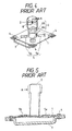
- Fig. 4 shows a conventional load sensor used with a pointing device as disclosed in Japanese Patent First Publication No. 7-174646.
- the load sensor includes an elastic plate 1, a rigid operating lever 2, and first and second strain gauge pairs 5 and 6.
- the first and second strain gauge pairs 5 and 6 include strain gauges 5a and 5b and strain gauges 6a and 6b, respectively, which are attached to the elastic plate 1 around the operating lever 2 at intervals of 90°.
- the elastic plate 1 is installed at four support points on a mount base 3 using fixtures 4.
- the magnitude of the applied force is determined by finding a difference in resistance between the strain gauges 5a and 5b and doubling it.
- the strain gauges 6a and 6b of the second pair both experience only torsional stress in the same direction so that a change in resistance does not occur.
- the load sensor is designed to detect only a component of the applied force along an axis of coordinate passing through the first pair of strain gauges 5a and 5b.
- the load sensor detects a component of the applied force along an axis of coordinate passing through the strain gauges 6a and 6b of the second pair.
- the load sensor resolves the force applied to the operating lever 2 into two components along x and y axes of a two dimensional coordinate system to determine the magnitude and direction of the applied force.
- a load sensor comprising:
- the pivot is formed on the mount base which supports the first end of the operating member so as to absorb a vertical component of the load acting perpendicular to the elastic plate.
- Each of the strain detecting elements may be made of a strain sensitive element printed on the elastic plate or a strain gauge bonded to the elastic plate.
- the mount base may include a bottom, a side wall surrounding the bottom and flanges extending vertically from a periphery of the bottom.
- the elastic plate is installed on the flanges so as to cover the bottom.
- the pivot is formed on the bottom.
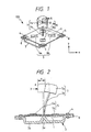
- a load sensor 100 according to the first example which is employed as a pointing device.
- the load sensor 100 generally includes an elastic plate 1, an operating shaft or lever 7, first and second strain sensitive element pairs 5 and 6, and a mount base 3.
- the elastic plate 1 is installed at four support points on the mount base 3 using fixtures 4.
- the operating lever 7 is installed in the center of the elastic plate 1 and includes a head 7a made of a rigid material and a straight support shaft 7b made of an elastic metal.
- the mount base 3 is made of a pressed rigid member including a bottom 3b, four flanges 8, and a conical protrusion or pivot 3a.
- the flanges 8 extend vertically from four corners of the bottom 3b and support the elastic plate 1.
- the pivot 3a is formed on the center of the bottom.
- the support shaft 7b is, as clearly shown in Fig.
- the support shaft 7b supports at an upper end the head 7a so that when a lateral load or force is applied to the head 7a of the operating lever 7 from any direction, the elastic plate 1 is deformed without being subjected to a vertical load directly from the support shaft 7b.
- the first and second strain sensitive element pairs 5 and 6 include strain sensitive elements 5a and 5b and strain sensitive elements 6a and 6b, respectively, which are attached to the elastic plate 1 symmetrically around the operating lever 7.
- the symmetrical arrangement of the four strain sensitive elements 5a to 6b means that they are disposed at angular intervals of 90°.
- the strain sensitive elements 5a and 5b of the first pair are, as apparent from the above, diametrically opposed to each other along a line (hereinafter, referred to as the x axis of a two-dimensional coordinate system).
- the strain sensitive elements 6a and 6b of the second pair are diametrically opposed to each other along a line (hereinafter, referred to as the y axis).
- the four strain sensitive elements 5a to 6b have the same resistance value.
- the lateral displacement F of the head 7a of the operating lever 7 is proportional to the lateral force P applied to the head 7a.
- the lateral force P applied to the head 7a of the operating lever 7 is translated into elastic deformation of the elastic plate 1 through the support shaft 7b, which is, in turn, sensed by the first and second strain sensitive element pairs 5 and 6.
- a desired amount of the lateral displacement of the head 7a of the operating lever 7 may be determined by adjusting the Young's modulus (i.e., material), the diameter, and/or the length of the support shaft 7b of the operating lever 7.
- the application of the elastic force to the elastic plate 1 from the support shaft 7b of the operating lever 7 causes the strain sensitive element 5a to be strained downward, while the strain sensitive element 5b is strained upward, thus resulting in a drop in resistance of the strain sensitive element 5a and a rise in resistance of the strain sensitive element 5b. This produces a difference in resistance between the strain sensitive elements 5a and 5b which can be monitored to determine the magnitude of the lateral force P applied to the operating lever 7.
- strain sensitive elements 6a and 6b of the second pair are subjected only to torsion, resulting in no change in resistance thereof.
- the resistance values only of the strain sensitive elements 6a and 6b are changed.
- the magnitude of the applied force can be determined by monitoring a difference in resistance between the strain sensitive elements 6a and 6b.
- a lateral force when a lateral force is applied to the operating lever 7 from any direction between the x and y axes, it may be measured in direction based on a ratio of a difference in resistance of the first strain sensitive element pair 5 to that of the second strain sensitive element pair 6 and in magnitude based on the sum of the differences in resistance of the first and second strain sensitive element pairs 5 and 6.
- the operating lever 7 is, as described above, supported on the pivot 3a of the base mount 3 vertically, thereby avoiding the deformation of the elastic plate 1 caused by a vertical component of a load applied to the operating lever 7. Specifically, only a lateral component of the applied load is measured accurately.
- the operating lever 7 may alternatively be formed only with the support shaft 7b.
- Each of the strain sensitive elements 5a to 6b may be made of a strain sensitive resistor printed on the elastic plate 1 or alternatively made of a strain gauge bonded to the elastic plate.
- Fig. 3 shows a load sensor 200 according to an embodiment of the invention which is different from the first example only in structure of an operating lever 9. Other arrangements are identical, and explanation thereof in detail will be omitted here.
- the operating lever 9 includes a head 9a, a compression coil spring 9b made of metallic wire, and a cylindrical lower mount 9c.
- the head 9a has formed thereon a boss 10 which is inserted into an end of the coil spring 9b in press-fit.
- the cylindrical lower mount 9b is inserted into the other end of the coil spring 9b in press-fit and has formed on the bottom thereof a projection 11 which is fitted into or bonded to a central opening of the elastic plate 1 and supported on the pivot 3a of the base mount 3.
- the use of the coil spring 9b results in an decrease in stress per unit area of the operating lever 9 when subjected to a lateral force and improves the fatigue of the operating lever 9.
- the pivot 3a is, as discussed above, provided for absorbing a vertical component of an applied load to prevent it from acting on the elastic plate 1 and may also be omitted.
Landscapes
- Physics & Mathematics (AREA)
- General Physics & Mathematics (AREA)
- Engineering & Computer Science (AREA)
- General Engineering & Computer Science (AREA)
- Theoretical Computer Science (AREA)
- Automation & Control Theory (AREA)
- Human Computer Interaction (AREA)
- Position Input By Displaying (AREA)
- Force Measurement Appropriate To Specific Purposes (AREA)
- Measurement Of Force In General (AREA)
- Switches With Compound Operations (AREA)
Claims (5)
- Capteur de charge comprenant :caractérisé en ce que :une base de montage (3) ;une plaque élastique (1) fixée sur ladite base de montage ;un élément d'actionnement (7) présentant une longueur donnée, ledit élément d'actionnement étant installé au niveau d'une première extrémité de celle-ci sur ladite plaque élastique (1) de façon à être plié en réponse à l'application d'une charge sur une deuxième extrémité opposée à la première extrémité, produisant une force élastique pour déformer ladite plaque élastique (1) ; etune pluralité d'éléments de détection de déformation (5, 6) fixés à ladite plaque élastique à des intervalles angulaires donnés ;ledit élément d'actionnement comprend une tête rigide (9a), un ressort hélicoïdal (9b), et un élément de montage (9c), la tête rigide (9a) et l'élément de montage (9c) étant ajustés dans les extrémités du ressort hélicoïdal (9b), respectivement, l'élément de montage (9c) étant disposé, par l'intermédiaire de ladite plaque élastique (1), sur un pivot (3a) formé sur ladite base de montage (3).
- Capteur de charge selon la revendication 1, dans lequel ledit pivot supporte la première extrémité dudit élément d'actionnement de façon à absorber une composante verticale de la charge agissant perpendiculairement à ladite plaque élastique.
- Capteur de charge selon la revendication 1 ou 2, dans lequel chacun desdits éléments de détection de déformation (5, 6) est constitué d'une jauge de contrainte.
- Capteur de charge selon la revendication 1, 2 ou 3, dans lequel chacun desdits éléments de détection de déformation (5, 6) est un élément sensible à la contrainte imprimé sur ladite plaque élastique (1).
- Capteur de charge selon la revendication 1, dans lequel ladite base de montage (3) comprend un fond et des bords s'étendant verticalement depuis une périphérie du fond, et dans lequel ladite plaque élastique (1) est installée sur les bords de façon à couvrir le fond, le pivot (3a) étant formé sur le fond.
Applications Claiming Priority (3)
| Application Number | Priority Date | Filing Date | Title |
|---|---|---|---|
| JP515/97 | 1997-01-07 | ||
| JP9000515A JPH10197373A (ja) | 1997-01-07 | 1997-01-07 | 荷重センサ |
| JP51597 | 1997-01-07 |
Publications (3)
| Publication Number | Publication Date |
|---|---|
| EP0852332A2 EP0852332A2 (fr) | 1998-07-08 |
| EP0852332A3 EP0852332A3 (fr) | 1998-07-29 |
| EP0852332B1 true EP0852332B1 (fr) | 2003-07-09 |
Family
ID=11475921
Family Applications (1)
| Application Number | Title | Priority Date | Filing Date |
|---|---|---|---|
| EP98300034A Expired - Lifetime EP0852332B1 (fr) | 1997-01-07 | 1998-01-06 | Structure sensible à une charge |
Country Status (2)
| Country | Link |
|---|---|
| EP (1) | EP0852332B1 (fr) |
| JP (1) | JPH10197373A (fr) |
Families Citing this family (7)
| Publication number | Priority date | Publication date | Assignee | Title |
|---|---|---|---|---|
| GB0523667D0 (en) * | 2005-11-21 | 2005-12-28 | In2Tec Ltd | Displacement sensor |
| JP5024358B2 (ja) | 2009-01-08 | 2012-09-12 | 株式会社日本自動車部品総合研究所 | 作用力検出装置 |
| JP2015102953A (ja) * | 2013-11-22 | 2015-06-04 | 株式会社デンソー | 操作入力装置 |
| CN105841856B (zh) * | 2016-05-10 | 2019-01-29 | 东南大学 | 一种感知接触点三维力位移与三维力的触须传感器 |
| JP6814923B1 (ja) * | 2020-05-27 | 2021-01-20 | 聡 横沢 | ポインティングデバイス |
| CN113125052B (zh) * | 2021-03-30 | 2022-05-27 | 于智育 | 一种压力传感器及其检测方法 |
| CN114688410B (zh) * | 2022-03-30 | 2023-08-25 | 杭州任达荷重监控技术有限公司 | 一种带有附着式传感器安装通孔的轴载荷监控支架 |
Family Cites Families (3)
| Publication number | Priority date | Publication date | Assignee | Title |
|---|---|---|---|---|
| JP3039286B2 (ja) * | 1993-10-01 | 2000-05-08 | 松下電器産業株式会社 | 荷重センサ |
| JP2584201B2 (ja) * | 1994-01-14 | 1997-02-26 | インターナショナル・ビジネス・マシーンズ・コーポレイション | 力変換器、コンピュータ・システムおよびキーボード |
| JPH0887375A (ja) * | 1994-09-16 | 1996-04-02 | Fujitsu Ltd | ポインティングデバイス |
-
1997
- 1997-01-07 JP JP9000515A patent/JPH10197373A/ja active Pending
-
1998
- 1998-01-06 EP EP98300034A patent/EP0852332B1/fr not_active Expired - Lifetime
Also Published As
| Publication number | Publication date |
|---|---|
| EP0852332A2 (fr) | 1998-07-08 |
| EP0852332A3 (fr) | 1998-07-29 |
| JPH10197373A (ja) | 1998-07-31 |
Similar Documents
| Publication | Publication Date | Title |
|---|---|---|
| EP1189045B1 (fr) | Capteur de charge muni d'un élément générateur de contraintes ayant des jauges de contraintes | |
| EP0388346B1 (fr) | Appareil avec un écran de visualisation sensible au toucher | |
| US10635248B2 (en) | Force sensor mount and related housings and systems that incorporate the same | |
| CN100390509C (zh) | 隔膜式负荷检测传感器、负荷检测部件及使用它们的电子秤 | |
| EP0852332B1 (fr) | Structure sensible à une charge | |
| US5231879A (en) | Semiconductor acceleration detecting apparatus | |
| WO2002014807A1 (fr) | Balance | |
| JPH0572060A (ja) | 歪みゲージトランスデユーサ | |
| KR20040066883A (ko) | 센서 장치 | |
| JP2002228516A (ja) | 重量測定装置 | |
| JPH05215624A (ja) | タッチパネルを支持し、かつタッチパネルにかかる力を測定するための装置 | |
| US4938065A (en) | Acceleration detecting device | |
| JP2020153949A (ja) | センサ装置 | |
| JP3444810B2 (ja) | シート重量計測装置 | |
| TWI794448B (zh) | 扭力壓力感測裝置及電動起子 | |
| JP4230241B2 (ja) | 触圧センサ、把持ロボット | |
| US5005429A (en) | Weigh module | |
| JPH11281665A (ja) | 半導体加速度センサ | |
| JPH085475A (ja) | 荷重センサ | |
| JP7601977B2 (ja) | 振動センサ | |
| JP3823886B2 (ja) | 電子天びん | |
| US11762472B2 (en) | Input device and input module | |
| JPH0639334Y2 (ja) | 力学量センサ | |
| JP2636015B2 (ja) | 加速度センサ | |
| JP2003240633A (ja) | シート重量計測装置 |
Legal Events
| Date | Code | Title | Description |
|---|---|---|---|
| PUAI | Public reference made under article 153(3) epc to a published international application that has entered the european phase |
Free format text: ORIGINAL CODE: 0009012 |
|
| PUAL | Search report despatched |
Free format text: ORIGINAL CODE: 0009013 |
|
| 17P | Request for examination filed |
Effective date: 19980112 |
|
| AK | Designated contracting states |
Kind code of ref document: A2 Designated state(s): FI FR GB |
|
| AX | Request for extension of the european patent |
Free format text: AL;LT;LV;MK;RO;SI |
|
| AK | Designated contracting states |
Kind code of ref document: A3 Designated state(s): AT BE CH DE DK ES FI FR GB GR IE IT LI LU MC NL PT SE |
|
| AX | Request for extension of the european patent |
Free format text: AL;LT;LV;MK;RO;SI |
|
| AKX | Designation fees paid |
Free format text: FI FR GB |
|
| RBV | Designated contracting states (corrected) |
Designated state(s): FI FR GB |
|
| REG | Reference to a national code |
Ref country code: DE Ref legal event code: 8566 |
|
| 17Q | First examination report despatched |
Effective date: 20010220 |
|
| GRAH | Despatch of communication of intention to grant a patent |
Free format text: ORIGINAL CODE: EPIDOS IGRA |
|
| GRAA | (expected) grant |
Free format text: ORIGINAL CODE: 0009210 |
|
| GRAH | Despatch of communication of intention to grant a patent |
Free format text: ORIGINAL CODE: EPIDOS IGRA |
|
| AK | Designated contracting states |
Designated state(s): FI FR GB |
|
| REG | Reference to a national code |
Ref country code: GB Ref legal event code: FG4D |
|
| ET | Fr: translation filed | ||
| PLBE | No opposition filed within time limit |
Free format text: ORIGINAL CODE: 0009261 |
|
| STAA | Information on the status of an ep patent application or granted ep patent |
Free format text: STATUS: NO OPPOSITION FILED WITHIN TIME LIMIT |
|
| 26N | No opposition filed |
Effective date: 20040414 |
|
| PGFP | Annual fee paid to national office [announced via postgrant information from national office to epo] |
Ref country code: GB Payment date: 20070103 Year of fee payment: 10 |
|
| PGFP | Annual fee paid to national office [announced via postgrant information from national office to epo] |
Ref country code: FR Payment date: 20070109 Year of fee payment: 10 |
|
| PGFP | Annual fee paid to national office [announced via postgrant information from national office to epo] |
Ref country code: FI Payment date: 20080115 Year of fee payment: 11 |
|
| GBPC | Gb: european patent ceased through non-payment of renewal fee |
Effective date: 20080106 |
|
| REG | Reference to a national code |
Ref country code: FR Ref legal event code: ST Effective date: 20081029 |
|
| PG25 | Lapsed in a contracting state [announced via postgrant information from national office to epo] |
Ref country code: GB Free format text: LAPSE BECAUSE OF NON-PAYMENT OF DUE FEES Effective date: 20080106 |
|
| PG25 | Lapsed in a contracting state [announced via postgrant information from national office to epo] |
Ref country code: FR Free format text: LAPSE BECAUSE OF NON-PAYMENT OF DUE FEES Effective date: 20080131 |
|
| PG25 | Lapsed in a contracting state [announced via postgrant information from national office to epo] |
Ref country code: FI Free format text: LAPSE BECAUSE OF NON-PAYMENT OF DUE FEES Effective date: 20090106 |