EP0852980B1 - Vorrichtung und Verfahren zum Schneiden einer Scheiben-Einspannleiste - Google Patents
Vorrichtung und Verfahren zum Schneiden einer Scheiben-Einspannleiste Download PDFInfo
- Publication number
- EP0852980B1 EP0852980B1 EP98100201A EP98100201A EP0852980B1 EP 0852980 B1 EP0852980 B1 EP 0852980B1 EP 98100201 A EP98100201 A EP 98100201A EP 98100201 A EP98100201 A EP 98100201A EP 0852980 B1 EP0852980 B1 EP 0852980B1
- Authority
- EP
- European Patent Office
- Prior art keywords
- clamping
- plate
- strip
- pane
- face
- Prior art date
- Legal status (The legal status is an assumption and is not a legal conclusion. Google has not performed a legal analysis and makes no representation as to the accuracy of the status listed.)
- Expired - Lifetime
Links
Images


Classifications
-
- B—PERFORMING OPERATIONS; TRANSPORTING
- B23—MACHINE TOOLS; METAL-WORKING NOT OTHERWISE PROVIDED FOR
- B23D—PLANING; SLOTTING; SHEARING; BROACHING; SAWING; FILING; SCRAPING; LIKE OPERATIONS FOR WORKING METAL BY REMOVING MATERIAL, NOT OTHERWISE PROVIDED FOR
- B23D45/00—Sawing machines or sawing devices with circular saw blades or with friction saw discs
- B23D45/14—Sawing machines or sawing devices with circular saw blades or with friction saw discs for cutting otherwise than in a plane perpendicular to the axis of the stock, e.g. for making a mitred cut
-
- B—PERFORMING OPERATIONS; TRANSPORTING
- B23—MACHINE TOOLS; METAL-WORKING NOT OTHERWISE PROVIDED FOR
- B23D—PLANING; SLOTTING; SHEARING; BROACHING; SAWING; FILING; SCRAPING; LIKE OPERATIONS FOR WORKING METAL BY REMOVING MATERIAL, NOT OTHERWISE PROVIDED FOR
- B23D47/00—Sawing machines or sawing devices working with circular saw blades, characterised only by constructional features of particular parts
- B23D47/04—Sawing machines or sawing devices working with circular saw blades, characterised only by constructional features of particular parts of devices for feeding, positioning, clamping, or rotating work
Definitions
- the invention relates to a device for cutting a Disc clamping bar with disc contact surface, with a support surface for the clamping bar and a clamping device to apply a vertical to the bar clamping force directed to the contact surface.
- the invention relates also meets a method of cutting one Disc clamping surface having disc contact surface, wherein the washer clamp is clamped on a support surface becomes.
- An apparatus and a method of this type are e.g. out DE-A-2722335 known.
- a cutting machine is known from the publication DE 29509797 U1 Known for cutting leafy material.
- the cutting machine includes a support table for the goods and a clamping device, which presses the goods against the support table for clamping.
- an apparatus for cutting an elongated one Good for example, also from US-A-5,239,905 known.
- the device comprises a support surface for placing a bar to be cut by a clamping device pressed against a stop surface and thus fixed in position becomes.
- the stop surface extends vertically to the contact surface.
- the document DE-A1-27 22 335 discloses a miter saw for glass retaining strips of window and door frames.
- the miter saw has a clamping table with pneumatic clamping cylinders on, which act perpendicular to the surface of the clamping table. To cut a glass retaining bar to length, it is placed on the support table clamped by the tensioning cylinder and by a Saw unit arranged on a slide processed.
- the document DE-C1-34 09 731 discloses a table saw for sawing steel profile bars. It has one in a saw slot of a rotary saw circular saw blade and one on a machine upper part arranged non-rotatable clamping device for the workpiece to be sawn.
- the tensioner has a way piece stop and a clamping cylinder piston arrangement with clamping plate and clamping elements arranged under the clamping plate.
- the clamping device acts on the turntable resting workpiece with a force perpendicular to the turntable is directed.
- the document DE-A1-40 18 323 discloses a method and a device for machining workpieces in pairs Wood or plastic, in particular frame parts for windows, Doors or the like.
- the device has a tensioning device which fixes the workpiece from above, i.e. the workpiece with a perpendicular to the contact surface Force applied.
- a pressure device provided that the inner longitudinal side of the workpiece with a horizontally acting force is applied to the workpiece laterally to press against a workpiece stop.
- the document US 4,208,934 shows a device for cutting of a profile.
- the profile lies on one Contact surface and is against a side stop surface pressed.
- EP-A1-0 685 284 discloses an apparatus for Sawing a workpiece on an adjustable support surface lies on.
- Devices and methods of the aforementioned type are general known and are used for washer clamps (hereinafter cut to length).
- the clamping bars in turn, a glass or window pane is used, for example in a window frame.
- she have for this purpose a disk contact surface provided with a seal that interacts with the disc to be clamped, and one on an adjacent surface of the clamping bar provided clamping device which interacts with the frame.
- Another fixation of the clamping bar on the support surface performs the clamping device, for example by means of a Bolzens presses the clamping bar onto the support surface.
- a disadvantage of this device is the fact that especially miter cuts can not be made exactly, so that in the installed state between adjacent clamping bars unwanted gaps due to inaccuracies in fit form. This is because the clamping bars caused by the disc tension can be slightly tilted. With that changed the position of the cut surface, so that a full-surface system on the adjacent clamping bar is no longer possible. Furthermore, the seals of adjacent clamping strips overlap in the installed state, which for aesthetic reasons is undesirable.
- the object of the present invention is therefore to to provide an apparatus and method that is accurate Allow the clamping bars to be cut to length.
- the object underlying the invention is achieved by a device of the type mentioned, which is a means of Tilting the washer clamp around its longitudinal axis.
- the agent formed such that it is the disc contact surface Disc clamping bar with a parallel to the contact surface applied force.
- the agent comprises a Plate which is connected to the washer contact surface of the clamping bar, preferably by means of a pneumatic drive is feasible.
- the drive a sling assigned to the relocation of the Limited in the direction of the disc contact surface.
- the sling comprises an adjustable screw which cooperates with a corresponding stop surface.
- This sling allows you to easily on adjust the disc clamping bar and thus force to different circumstances, like different ones Slice thickness, adjust.
- the support surface is designed as a counter plate, the groove has a projection provided on the clamping bar intervenes.
- a extending parallel to the support surface guide rod provided, one end of which cooperates with the drive and to which the plate is attached.
- the counter plate is like this trained that the clamping bar is positioned so that the disc contact surface of the feed direction of a saw blade is turned away.
- the lifting means comprises a rotatable support element on which several screws are arranged are.
- the carrier element is preferably circular and the screws on an imaginary circular line evenly spaced apart.
- the object underlying the invention is achieved by a method solved the type mentioned, characterized in that is that the washer clamp around its longitudinal axis is tilted and cut in this position.
- the Disc contact surface for tilting with a parallel to the contact surface applied force.
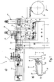
- FIG. 1 shows part of a cutting device 1, which comprises a support table 5 attached to a support 3.
- the carrier 3 is part of the entire frame of the sawing device, which is not shown for clarity.
- the support table 5 extending perpendicular to the plane of the drawing comprises a counter plate 7, which is preferably detachable again the upper surface 9 of the support table 5 arranged in FIG is.
- Counter plate 7 In a surface facing away from the upper table surface 9
- Counter plate 7 are two spaced apart parallel grooves extending perpendicular to the plane of the drawing 11 provided for the fixation and positioning of clamping bars 13 serve.
- Such a clamping bar is shown on an enlarged scale in FIG. 1b 13 shown.
- a sealing unit 15, hereinafter referred to as a seal referred to on a in the following as a disc contact surface 17 designated side is provided.
- This investment area 17 with the seal 15 is for clamping a disc 19 in a frame composed of profile pieces against pressed the edge region of the disc 19 and connected to the frame.
- a hook-shaped projection 21 on one of the disc contact surface 17 adjacent page 23 is provided.
- This projection 21 works in the installed state with a suitably trained Profiling clamped together in the frame. In the built-in State are thus only the side surfaces 25 and 27 of the Clamping bar 13 visible from the outside.
- clamping bar 13 For cutting such a clamping bar 13 to a frame appropriate size is the clamping bar 13 on the counter plate 7 hung up. For exact position positioning and one first fixation on the counter plate 7 engage the projections 21 in the grooves 11. In the present embodiment lie on the counter plate 7 two clamping strips 13 for cutting to length parallel to each other.
- clamping devices 29 rendered. They each include one perpendicular to the counter plate 7 extending rod 31, which by means of a Drive, preferably a pneumatic drive in their Longitudinal direction, i.e. displaceable perpendicular to the counter plate 7 is. At one end of the rod 31 facing the counter plate 7 a tensioning element 33, preferably made of rubber, is attached, that cooperates with the tension bar 13. For positioning of the clamping element 33 relative to that lying on the counter plate 7 Clamping bar 13 is the clamping element on a shaft 35 attached, which is parallel to the counter plate 7 and transverse to the Longitudinal direction of the disk clamping bar 13 is displaceable.
- the drive required for relocation preferably a pneumatic one Drive, is for clarity in the figures not shown.
- the sawing device 1 also has at least one saw blade 37 on a carriage in the direction of arrow P, the means perpendicular to the longitudinal direction of the counterplate 7 overlying clamping bar 13 is displaceably arranged.
- the figure is only representative for the entire unit - the saw blade 37 is shown.
- the saw blade 37 from the in Figure 1 shown lying parallel to the plane of the drawing tiltable about an axis A, usually around one Angle of 45 °.
- the saw device 1 has a parallel to the Counter plate 7 extending shaft 41, which by means of a pneumatic drive 43 transverse to the longitudinal direction of the clamping bar 13 is relocatable.
- a pneumatic drive 43 transverse to the longitudinal direction of the clamping bar 13 is relocatable.
- On one of the counter plate 7 facing The ends of the shaft 41 are spaced apart in the longitudinal direction of the shaft mutually arranged arms 45 are provided, which are extend perpendicular to the counter plate 7 towards this.
- Two stop means 47, 49 are attached to the shaft 41, with the help of the displacement of the shaft 41 in both directions, that is, in Figure 1 to the left and to the right, limited becomes.
- the stop means 47 acts to limit the movement right together with a fixed stop 51, while the second stop means 49 for limiting to the left with a also stationary stop 53 cooperates.
- the sling 49 is set so that the arms 45 one position take that allow insertion of the clamping bars 13.
- the sling 47 is adjusted so that the arms 45 by displacing the shaft 41 in contact with the contact surface 17 can be brought.
- the arm 45 can be more or less strongly against the contact surface 17 or press the seal 15.
- the clamping bars 13 are arranged on the counter plate 7 so that the acting from the arms 45 on the contact surface 17 Force opposite to the feed direction P of the saw unit is directed. The cutting direction is therefore from the visible Surface 25 to the contact surface 17.
- the coupling element 55 is a rectangular one Plate, as can be clearly seen in Figure 3.
- the coupling element 55 is constructed symmetrically to the plane of symmetry S.
- a bore 57, 57 ' is provided by the respective shaft is penetrated.
- a screw not shown can the diameter of the bore 57, 57 ', due to a gap extending from the hole to the edge of the plate, change so that a clamping effect can be achieved.
- the two stop means 47, 47 'are as is clear in Figure 3 recognizable, symmetrical to the axis S by means of a screw connection on the coupling element 55 in the longitudinal axis of the plate upper half attached.
- the sling means 47, 47 ' comprise a support 61, 61' which is circular in plan view, in the equidistant bores 63, 63 'lying on a circle are introduced.
- the holes 63 are used to receive Screws 65, 65 ', the screw head as the actual stop works.
- the two carriers 61, 61 'are on the coupling element 55 arranged so that only - with respect to the representation in Figure 3 - bottom screw 67, 67 'with the counter stop 51, 51 'cooperates.
- the screws 65 are different long selected or different distances in the Screwed holes, a sling can be achieved, that can be changed very easily by rotating the carrier 61, 61 ' is.
- the stop means 49, 49 'shown in FIG. 2 are identical to the stop means 47, 47 ', so that on a repeated description is omitted.
- the displacement of the two shafts 41, 41 'and thus the arms 45, 45 'in the opposite direction of the arrow K are the two slings 49, 49 ', however, rotated by 180 ° on one Coupling element 69, that is to say on its coupling element 55 Surface attached.
- the coupling element 69 itself is the same Formed as the coupling element 55 and with the Shafts 41, 41 'connected. Only the one for connecting with the drive 43 provided hole is missing.
- FIG. 3 also shows that the two arms 45, 45 'carry a plate 77 which is fastened by screws.
- This plate 77 extends - with respect to the representation in FIG Figure 3 - in the horizontal direction from the left arm 45 to right arm 45 '.
- the vertical extension should be be chosen larger than the maximum height h of a to be cut Clamping bar 13.
- the plate 77 is an edge open to the counter plate 7 out Breakthrough 79 formed, the shape of which is chosen so that the Saw blade 37 in different angular positions in the direction of the arrow P - in Figure 3 perpendicular to the plane of the drawing without colliding with the plate 77.
- the shape of the opening 79 is to be selected so that in the counter region 7 adjacent edge area of the plate 77 - seen in the longitudinal direction - the largest possible area arises, which - as explained later - with the contact surface 17 a clamping bar 13 is to be brought into contact.
- this plate 77 which when sawing simulates a glass or window pane, with reference to FIG. 3 vertically displaceable to the plane of the drawing, the slings 47, 47 'the shift in the direction of the clamping bars 13 limit.
- the two plates 77 are in their right End position in which the stop means 47 is effective by means of of the drive 43 relocated.
- the plates 77 press with their lower edge area against the contact surfaces 17 of the two Clamping strips 13 and thus cause deformation of the seals 15. The extent of this deformation can be with the help of Adjust lifting gear 47.
- the on the clamping bar 13 acting force causes the clamping bar 13 to tilt around an axis parallel to the longitudinal axis of the clamping bar runs. In Figure 1, this tilting is only by one example of an angle of 2 °.
- the saw blade 37 is now in the direction of arrow P relocated and sawn the clamping bars.
- the saw blade 37 can be pivoted, as shown in FIG. 3, so that miter cuts are also possible. That with miter cuts resulting waste piece 75 then falls through Openings 73 in the counter plate 7 from the cutting area out below.
- the arrangement of the clamping bars 13 with their contact surfaces 17 directed to the drive 43 has the advantage that the visible Surfaces 25, 27 are sawn from the outside in, so that none visible burr formation occurs.
- FIG 4 is a second embodiment of a sawing device 1, which is essentially that with reference to FIG Figures 1 to 3 described embodiment corresponds. On the description of the same reference numerals parts marked in Figures 1 to 3 is therefore waived.
- the device 1 differs from that previously described device only in that the clamping bars 13 are placed on the counter plate 7 in this way, that their contact surfaces 17 face away from the drive 43.
- Corresponding are the plates 77 on the arms 45 on the drive 43 facing sides attached and consequently act the clamping bars 13 by moving in the direction of Arrow P with a force acting in the same direction.
- the lifting means 49 the displacement - with reference to FIG. 4 - limited to the left is the measure of the force acting on it Adjust sling 49.
- the functions of the two slings 47, 49 are thus compared to the first embodiment reversed.
Landscapes
- Engineering & Computer Science (AREA)
- Mechanical Engineering (AREA)
- Sawing (AREA)
- Re-Forming, After-Treatment, Cutting And Transporting Of Glass Products (AREA)
- Finish Polishing, Edge Sharpening, And Grinding By Specific Grinding Devices (AREA)
- Details Of Cutting Devices (AREA)
Description
- Figur 1a
- eine Seitenansicht der erfindungsgemäßen Vorrichtung,
- Figur 1b
- eine schematische Darstellung einer Einspannleiste im Querschnitt,
- Figur 2
- die erfindungsgemäße Vorrichtung in Draufsicht,
- Figur 3
- die erfindungsgemäße Vorrichtung in einer Vorderansicht, und
- Figur 4
- ein zweites Ausführungsbeispiel der erfindungsgemäßen Vorrichtung.
Claims (16)
- Vorrichtung zum Schneiden einer eine Scheibenanlagefläche (17) aufweisenden Scheiben-Einspannleiste (13), mit einer Auflagefläche (7) für die Scheiben-Einspannleiste (13), und einer Spanneinrichtung (29) zur Beaufschlagung der Leiste (13) mit einer senkrecht zur Auflagefläche (7) wirkenden Einspannkraft, gekennzeichnet durch ein Mittel (41,43,45,77) zum Verkippen der Scheiben-Einspannleiste (13) um deren Längsachse.
- Vorrichtung nach Anspruch 1, dadurch gekennzeichnet, daß das Mittel (41,43,45,77) zur Beaufschlagung der Scheibenanlagefläche (17) der Einspannleiste (13) mit einer parallel zur Auflagefläche (7) gerichteten Kraft ausgebildet ist.
- Vorrichtung nach Anspruch 2, dadurch gekennzeichnet, daß das Mittel eine Platte (77) aufweist, die in Kontakt mit der Anlagefläche (17) bringbar ist.
- Vorrichtung nach Anspruch 3, dadurch gekennzeichnet, daß die Platte (77) mittels eines Antriebs (43) parallel zur Auflagefläche (7) verlagerbar angeordnet ist.
- Vorrichtung nach Anspruch 4, dadurch gekennzeichnet, daß der Antrieb ein pneumatischer Antrieb (43) ist.
- Vorrichtung nach Anspruch 4 oder 5, dadurch gekennzeichnet, daß dem Antrieb (43) ein Anschlagmittel (47;49) zugeordnet ist, das die Verlagerung der Platte (77) begrenzt, derart, daß eine vordefinierte Position erreichbar ist.
- Vorrichtung nach Anspruch 6, dadurch gekennzeichnet, daß das Anschlagmittel (47) zumindest eine einstellbare Schraube (67) aufweist, die mit einer ortsfest angeordneten Gegenanschlagfläche (51) zusammenwirkt.
- Vorrichtung nach einem der vorhergehenden Ansprüche, dadurch gekennzeichnet, daß eine die Auflagefläche bildende Konterplatte (7) vorgesehen ist, in der eine Nut (11) ausgebildet ist.
- Vorrichtung nach einem der vorhergehenden Ansprüche, dadurch gekennzeichnet, daß zumindest eine parallel zur Auflagefläche (7) verlaufende Welle (41) angeordnet ist, die mit dem Antrieb (43) gekoppelt und an der die Platte (77) angebracht ist.
- Vorrichtung nach Anspruch 9, dadurch gekennzeichnet, daß an der Welle (41) ein sich senkrecht zur Auflagefläche (7) erstreckender Arm (45) angebracht ist, wobei der Arm (45) die Platte (77) trägt.
- Vorrichtung nach Anspruch 8, dadurch gekennzeichnet, daß die Konterplatte (7) so ausgebildet ist, daß die Anlagefläche der Einspannleiste (13) der Säge - in deren Vorschubrichtung gesehen - abgewandt ist.
- Vorrichtung nach Anspruch 9, dadurch gekennzeichnet, daß in der Konterplatte (7) im Sägebereich Öffnungen (71,73) vorgesehen sind, die als Abfallöffnungen dienen.
- Vorrichtung nach Anspruch 6, dadurch gekennzeichnet, daß das Anschlagmittel (47) ein drehbares Trägerelement (61) umfaßt, an dem mehrere Schrauben (63) angeordnet sind.
- Vorrichtung nach Anspruch 13, dadurch gekennzeichnet, daß das Trägerelement (61) im Querschnitt kreisförmig ausgebildet ist, und daß die Schrauben auf einer Kreislinie gleichmäßig beabstandet zueinander angeordnet sind.
- Verfahren zum Schneiden einer eine Scheibenanlagefläche (17) aufweisenden Scheiben-Einspannleiste (13), wobei die Scheiben-Einspannleiste (13) auf einer Auflagefläche (7) über eine Spanneinrichtung (29) festgeklemmt wird, dadurch gekennzeichnet, daß die Scheiben-Einspannleiste (13) um eine parallel zu ihrer Längsachse verlaufenden Achse gekippt und in dieser Position geschnitten wird.
- Verfahren nach Anspruch 15, dadurch gekennzeichnet, daß die Scheibenanlagefläche (17) zum Verkippen mit einer parallel zur Auflagefläche (7) gerichteten Kraft beaufschlagt wird.
Applications Claiming Priority (2)
| Application Number | Priority Date | Filing Date | Title |
|---|---|---|---|
| DE19700977 | 1997-01-14 | ||
| DE19700977A DE19700977C2 (de) | 1997-01-14 | 1997-01-14 | Vorrichtung und Verfahren zum Schneiden einer Scheiben-Einspannleiste |
Publications (3)
| Publication Number | Publication Date |
|---|---|
| EP0852980A1 EP0852980A1 (de) | 1998-07-15 |
| EP0852980B1 true EP0852980B1 (de) | 1999-09-29 |
| EP0852980B2 EP0852980B2 (de) | 2005-01-12 |
Family
ID=7817321
Family Applications (1)
| Application Number | Title | Priority Date | Filing Date |
|---|---|---|---|
| EP98100201A Expired - Lifetime EP0852980B2 (de) | 1997-01-14 | 1998-01-08 | Vorrichtung und Verfahren zum Schneiden einer Scheiben-Einspannleiste |
Country Status (3)
| Country | Link |
|---|---|
| EP (1) | EP0852980B2 (de) |
| AT (1) | ATE185099T1 (de) |
| DE (2) | DE19700977C2 (de) |
Families Citing this family (2)
| Publication number | Priority date | Publication date | Assignee | Title |
|---|---|---|---|---|
| DE10129291A1 (de) * | 2001-06-18 | 2002-12-19 | Jochen Spoerl | Verfahren und Vorrichtung zum Schneiden bzw. Zerspanen von Weichmaterialteilen an Hartmaterialkörpern |
| CN111516026B (zh) * | 2020-04-29 | 2021-01-08 | 太仓大中包装材料有限公司 | 一种泡沫塑料隔板二次加工成型机械 |
Family Cites Families (8)
| Publication number | Priority date | Publication date | Assignee | Title |
|---|---|---|---|---|
| DE7715720U1 (de) * | 1977-05-17 | 1978-11-02 | Haffner Gmbh & Co Gotthold | Gehrungssaege fuer glashalteleisten von fenster- und tuerrahmen |
| US4208934A (en) * | 1979-03-20 | 1980-06-24 | Wall Leslie W | Miter saw machine |
| DE3409731C1 (de) * | 1984-03-16 | 1985-08-22 | Peddinghaus, Rolf, Dipl.-Ing., 5828 Ennepetal | Tischkreissäge, insbesondere zum Sägen von Stahlprofilstäben |
| DE4018323C2 (de) * | 1990-06-08 | 1995-05-24 | Ludolf Stegherr | Einrichtung zum paarweisen Bearbeiten von Werkstücken aus Holz oder Kunststoff,insbesondere von Rahmenteilen für Fenster, Türen oder dgl. |
| US5158124A (en) * | 1991-10-04 | 1992-10-27 | Aluminum Company Of America | Double-end round top component cut-off saw |
| US5239905A (en) * | 1992-10-19 | 1993-08-31 | Dunn Gail E | Miter table molding positioning apparatus |
| EP0685284A1 (de) * | 1994-06-03 | 1995-12-06 | Li-Lin Chang | Sägetisch mit Werkstückspannvorrichtung |
| DE29509797U1 (de) * | 1995-06-16 | 1995-08-31 | Adolf Mohr Maschinenfabrik GmbH & Co. KG, 65719 Hofheim | Schneidmaschine zum Schneiden von blättrigem Gut |
-
1997
- 1997-01-14 DE DE19700977A patent/DE19700977C2/de not_active Expired - Fee Related
-
1998
- 1998-01-08 AT AT98100201T patent/ATE185099T1/de not_active IP Right Cessation
- 1998-01-08 DE DE59800030T patent/DE59800030D1/de not_active Expired - Lifetime
- 1998-01-08 EP EP98100201A patent/EP0852980B2/de not_active Expired - Lifetime
Also Published As
| Publication number | Publication date |
|---|---|
| EP0852980B2 (de) | 2005-01-12 |
| EP0852980A1 (de) | 1998-07-15 |
| ATE185099T1 (de) | 1999-10-15 |
| DE59800030D1 (de) | 1999-11-04 |
| DE19700977A1 (de) | 1998-12-10 |
| DE19700977C2 (de) | 2002-01-17 |
Similar Documents
| Publication | Publication Date | Title |
|---|---|---|
| EP3581310A1 (de) | Sägemaschine für gehrungsschnitte | |
| DE2533201A1 (de) | Verfahren und vorrichtung zum saegen eines laenglichen werkstueckes | |
| AT406657B (de) | Vorrichtung zum festklemmen eines zerspanungsmessers | |
| EP1517763B1 (de) | Metallbandsäge mit aufgehängtem sägerahmen | |
| EP0330970A2 (de) | Vorrichtung zum Positionieren von bogenförmigen Kreuzsprossenrahmenteilen und zum Fräsen von trapezförmigen Ausnehmungen in diese Rahmenteile | |
| DE9214430U1 (de) | Horizontalbandsäge | |
| AT3637U1 (de) | Führungsvorrichtung für ein sägeblatt führungsvorrichtung für ein sägeblatt | |
| EP0852980B1 (de) | Vorrichtung und Verfahren zum Schneiden einer Scheiben-Einspannleiste | |
| DE19828030B4 (de) | Vorrichtung zur Bearbeitung von Rahmenschenkeln | |
| DE3203447A1 (de) | Keilschnittsaege | |
| EP0600049A1 (de) | Rollschneideinheit | |
| DE4409813C2 (de) | Vorrichtung zum Zuschneiden von stabförmigen Werkstücken, insbesondere von Glassprossen für Fenster oder Türen | |
| DE3422101C2 (de) | ||
| DE202006001351U1 (de) | Sägemaschine mit einem Sägewerkzeug und mit einem diesem benachbarten Bohraggregat | |
| DE3703874C2 (de) | ||
| EP1764177B1 (de) | Ablängvorrichtung für Glasleisten oder entsprechende Stabprofile und Verfahren zum Ablängen von Glasleisten oder entsprechenden Stabprofilen | |
| DE19827098B4 (de) | Verfahren und Vorrichtung zum Abtrennen von Profilstäben aus Kunststoff oder Leichtmetall | |
| DE4107946A1 (de) | Verfahren und vorrichtung zum fraesen von werkstuecken aus holz oder holzaehnlichem material | |
| DE3715518A1 (de) | Vorrichtung zur schlitzfraesenden oder bohrenden bearbeitung von fensterprofilen | |
| DE19811668B4 (de) | Bearbeitungsaggregat, insbesondere Klinkschnittsäge | |
| DE3219364C2 (de) | Zuschnitteinrichtung für Glashalteleisten von Fenstern | |
| EP0689907B1 (de) | Holzbearbeitungsmaschine | |
| DE3105470A1 (de) | Foerdereinrichtung fuer stahlprofile | |
| DE19758436C2 (de) | Sägevorrichtung mit Vorritzer | |
| DE19861270B4 (de) | Vorrichtung zur Bearbeitung von Rahmenschenkeln |
Legal Events
| Date | Code | Title | Description |
|---|---|---|---|
| PUAI | Public reference made under article 153(3) epc to a published international application that has entered the european phase |
Free format text: ORIGINAL CODE: 0009012 |
|
| AK | Designated contracting states |
Kind code of ref document: A1 Designated state(s): AT BE CH DE DK ES FI FR GB IT LI NL |
|
| AX | Request for extension of the european patent |
Free format text: AL;LT;LV;MK;RO;SI |
|
| 17P | Request for examination filed |
Effective date: 19981008 |
|
| GRAG | Despatch of communication of intention to grant |
Free format text: ORIGINAL CODE: EPIDOS AGRA |
|
| 17Q | First examination report despatched |
Effective date: 19990108 |
|
| GRAG | Despatch of communication of intention to grant |
Free format text: ORIGINAL CODE: EPIDOS AGRA |
|
| GRAH | Despatch of communication of intention to grant a patent |
Free format text: ORIGINAL CODE: EPIDOS IGRA |
|
| AKX | Designation fees paid |
Free format text: AT BE CH DE DK ES FI LI |
|
| RBV | Designated contracting states (corrected) |
Designated state(s): AT BE CH DE DK ES FI LI |
|
| RBV | Designated contracting states (corrected) |
Designated state(s): AT BE CH DE DK ES FI FR GB IT LI NL |
|
| GRAH | Despatch of communication of intention to grant a patent |
Free format text: ORIGINAL CODE: EPIDOS IGRA |
|
| GRAA | (expected) grant |
Free format text: ORIGINAL CODE: 0009210 |
|
| AK | Designated contracting states |
Kind code of ref document: B1 Designated state(s): AT BE CH DE DK ES FI FR GB IT LI NL |
|
| PG25 | Lapsed in a contracting state [announced via postgrant information from national office to epo] |
Ref country code: NL Free format text: LAPSE BECAUSE OF FAILURE TO SUBMIT A TRANSLATION OF THE DESCRIPTION OR TO PAY THE FEE WITHIN THE PRESCRIBED TIME-LIMIT Effective date: 19990929 Ref country code: IT Free format text: LAPSE BECAUSE OF FAILURE TO SUBMIT A TRANSLATION OF THE DESCRIPTION OR TO PAY THE FEE WITHIN THE PRE;WARNING: LAPSES OF ITALIAN PATENTS WITH EFFECTIVE DATE BEFORE 2007 MAY HAVE OCCURRED AT ANY TIME BEFORE 2007. THE CORRECT EFFECTIVE DATE MAY BE DIFFERENT FROM THE ONE RECORDED.SCRIBED TIME-LIMIT Effective date: 19990929 Ref country code: GB Free format text: LAPSE BECAUSE OF FAILURE TO SUBMIT A TRANSLATION OF THE DESCRIPTION OR TO PAY THE FEE WITHIN THE PRESCRIBED TIME-LIMIT Effective date: 19990929 Ref country code: FI Free format text: LAPSE BECAUSE OF NON-PAYMENT OF DUE FEES Effective date: 19990929 Ref country code: ES Free format text: THE PATENT HAS BEEN ANNULLED BY A DECISION OF A NATIONAL AUTHORITY Effective date: 19990929 |
|
| REF | Corresponds to: |
Ref document number: 185099 Country of ref document: AT Date of ref document: 19991015 Kind code of ref document: T |
|
| REG | Reference to a national code |
Ref country code: CH Ref legal event code: EP |
|
| REF | Corresponds to: |
Ref document number: 59800030 Country of ref document: DE Date of ref document: 19991104 |
|
| ET | Fr: translation filed | ||
| PG25 | Lapsed in a contracting state [announced via postgrant information from national office to epo] |
Ref country code: DK Free format text: LAPSE BECAUSE OF FAILURE TO SUBMIT A TRANSLATION OF THE DESCRIPTION OR TO PAY THE FEE WITHIN THE PRESCRIBED TIME-LIMIT Effective date: 19991229 |
|
| PG25 | Lapsed in a contracting state [announced via postgrant information from national office to epo] |
Ref country code: BE Free format text: LAPSE BECAUSE OF NON-PAYMENT OF DUE FEES Effective date: 20000131 |
|
| NLV1 | Nl: lapsed or annulled due to failure to fulfill the requirements of art. 29p and 29m of the patents act | ||
| GBV | Gb: ep patent (uk) treated as always having been void in accordance with gb section 77(7)/1977 [no translation filed] |
Effective date: 19990929 |
|
| PLBQ | Unpublished change to opponent data |
Free format text: ORIGINAL CODE: EPIDOS OPPO |
|
| PLBI | Opposition filed |
Free format text: ORIGINAL CODE: 0009260 |
|
| BERE | Be: lapsed |
Owner name: EUGEN LUTZ G.M.B.H. & CO. MASCHINENFABRIK Effective date: 20000131 |
|
| PLBF | Reply of patent proprietor to notice(s) of opposition |
Free format text: ORIGINAL CODE: EPIDOS OBSO |
|
| 26 | Opposition filed |
Opponent name: RAPID MASCHINENBAU GMBH Effective date: 20000629 |
|
| PLBF | Reply of patent proprietor to notice(s) of opposition |
Free format text: ORIGINAL CODE: EPIDOS OBSO |
|
| RAP2 | Party data changed (patent owner data changed or rights of a patent transferred) |
Owner name: ELUMATEC GMBH & CO. KG |
|
| PG25 | Lapsed in a contracting state [announced via postgrant information from national office to epo] |
Ref country code: LI Free format text: LAPSE BECAUSE OF NON-PAYMENT OF DUE FEES Effective date: 20020131 Ref country code: CH Free format text: LAPSE BECAUSE OF NON-PAYMENT OF DUE FEES Effective date: 20020131 |
|
| REG | Reference to a national code |
Ref country code: CH Ref legal event code: PL |
|
| PLBP | Opposition withdrawn |
Free format text: ORIGINAL CODE: 0009264 |
|
| PUAH | Patent maintained in amended form |
Free format text: ORIGINAL CODE: 0009272 |
|
| STAA | Information on the status of an ep patent application or granted ep patent |
Free format text: STATUS: PATENT MAINTAINED AS AMENDED |
|
| 27A | Patent maintained in amended form |
Effective date: 20050112 |
|
| AK | Designated contracting states |
Kind code of ref document: B2 Designated state(s): AT BE CH DE DK ES FI FR GB IT LI NL |
|
| REG | Reference to a national code |
Ref country code: ES Ref legal event code: FD2A Effective date: 20000110 |
|
| ET3 | Fr: translation filed ** decision concerning opposition | ||
| REG | Reference to a national code |
Ref country code: FR Ref legal event code: CJ Ref country code: FR Ref legal event code: CD |
|
| PGFP | Annual fee paid to national office [announced via postgrant information from national office to epo] |
Ref country code: FR Payment date: 20100223 Year of fee payment: 13 |
|
| PGFP | Annual fee paid to national office [announced via postgrant information from national office to epo] |
Ref country code: AT Payment date: 20100114 Year of fee payment: 13 |
|
| REG | Reference to a national code |
Ref country code: FR Ref legal event code: ST Effective date: 20110930 |
|
| PG25 | Lapsed in a contracting state [announced via postgrant information from national office to epo] |
Ref country code: FR Free format text: LAPSE BECAUSE OF NON-PAYMENT OF DUE FEES Effective date: 20110131 |
|
| PG25 | Lapsed in a contracting state [announced via postgrant information from national office to epo] |
Ref country code: AT Free format text: LAPSE BECAUSE OF NON-PAYMENT OF DUE FEES Effective date: 20110108 |
|
| PGFP | Annual fee paid to national office [announced via postgrant information from national office to epo] |
Ref country code: DE Payment date: 20120221 Year of fee payment: 15 |
|
| PG25 | Lapsed in a contracting state [announced via postgrant information from national office to epo] |
Ref country code: DE Free format text: LAPSE BECAUSE OF NON-PAYMENT OF DUE FEES Effective date: 20130801 |
|
| REG | Reference to a national code |
Ref country code: DE Ref legal event code: R119 Ref document number: 59800030 Country of ref document: DE Effective date: 20130801 |