EP0852993A1 - Kern zum Formen eines bogenformigen Hohlkörpers in einer Form und Formverfahren - Google Patents
Kern zum Formen eines bogenformigen Hohlkörpers in einer Form und Formverfahren Download PDFInfo
- Publication number
- EP0852993A1 EP0852993A1 EP98500002A EP98500002A EP0852993A1 EP 0852993 A1 EP0852993 A1 EP 0852993A1 EP 98500002 A EP98500002 A EP 98500002A EP 98500002 A EP98500002 A EP 98500002A EP 0852993 A1 EP0852993 A1 EP 0852993A1
- Authority
- EP
- European Patent Office
- Prior art keywords
- core
- movement
- internal
- shaped
- doughnut
- Prior art date
- Legal status (The legal status is an assumption and is not a legal conclusion. Google has not performed a legal analysis and makes no representation as to the accuracy of the status listed.)
- Ceased
Links
- 238000000465 moulding Methods 0.000 title claims description 14
- 238000000034 method Methods 0.000 title claims description 4
- 239000000463 material Substances 0.000 claims description 3
- 239000004743 Polypropylene Substances 0.000 description 1
- 239000004793 Polystyrene Substances 0.000 description 1
- 235000012489 doughnuts Nutrition 0.000 description 1
- 239000012530 fluid Substances 0.000 description 1
- 238000002347 injection Methods 0.000 description 1
- 239000007924 injection Substances 0.000 description 1
- 238000004519 manufacturing process Methods 0.000 description 1
- 239000004033 plastic Substances 0.000 description 1
- 229920003023 plastic Polymers 0.000 description 1
- -1 polypropylene Polymers 0.000 description 1
- 229920001155 polypropylene Polymers 0.000 description 1
- 229920002223 polystyrene Polymers 0.000 description 1
- 229920000915 polyvinyl chloride Polymers 0.000 description 1
- 239000004800 polyvinyl chloride Substances 0.000 description 1
- 238000007493 shaping process Methods 0.000 description 1
Images


Classifications
-
- B—PERFORMING OPERATIONS; TRANSPORTING
- B29—WORKING OF PLASTICS; WORKING OF SUBSTANCES IN A PLASTIC STATE IN GENERAL
- B29C—SHAPING OR JOINING OF PLASTICS; SHAPING OF MATERIAL IN A PLASTIC STATE, NOT OTHERWISE PROVIDED FOR; AFTER-TREATMENT OF THE SHAPED PRODUCTS, e.g. REPAIRING
- B29C45/00—Injection moulding, i.e. forcing the required volume of moulding material through a nozzle into a closed mould; Apparatus therefor
- B29C45/17—Component parts, details or accessories; Auxiliary operations
- B29C45/26—Moulds
- B29C45/261—Moulds having tubular mould cavities
- B29C45/2614—Moulds having tubular mould cavities for manufacturing bent tubular articles using an undercut forming mould core
-
- B—PERFORMING OPERATIONS; TRANSPORTING
- B29—WORKING OF PLASTICS; WORKING OF SUBSTANCES IN A PLASTIC STATE IN GENERAL
- B29C—SHAPING OR JOINING OF PLASTICS; SHAPING OF MATERIAL IN A PLASTIC STATE, NOT OTHERWISE PROVIDED FOR; AFTER-TREATMENT OF THE SHAPED PRODUCTS, e.g. REPAIRING
- B29C33/00—Moulds or cores; Details thereof or accessories therefor
- B29C33/44—Moulds or cores; Details thereof or accessories therefor with means for, or specially constructed to facilitate, the removal of articles, e.g. of undercut articles
- B29C33/48—Moulds or cores; Details thereof or accessories therefor with means for, or specially constructed to facilitate, the removal of articles, e.g. of undercut articles with means for collapsing or disassembling
- B29C33/485—Moulds or cores; Details thereof or accessories therefor with means for, or specially constructed to facilitate, the removal of articles, e.g. of undercut articles with means for collapsing or disassembling cores or mandrels
Definitions
- This invention relates to a core for moulding a elbow in a mould, said elbow having: a centre region having a doughnut-shaped internal surface and two end regions having an internal cylindrical circular surface and defining respective axes.
- the invention also relates to a process for moulding a elbow using the said core.
- bow is used in the description and claims with the acceptation of a portion of tube bent in arcuate form, serving to vary the direction of a pipeline.
- a core of the type first mentioned above which is characterized in that it comprises two halves, each of which has a circular flat surface, said halves being suitable for occupying an active position in which said circular flat surfaces are juxtaposed and said halves become symmetrical relative to the plane of said circular flat surfaces, each half comprising: a core rear body member, formed by at least one part and which is formed with: [a] a first internal flat surface which, in said active position, is parallel to one of said axes; [b] a polyhedral projection extending from said internal flat surface, limited by two first lateral surfaces and at the front by a second flat surface parallel to said first internal flat surface; [c] a first external curved surface, having a cylindrical portion and a doughnut-shaped portion; and [d] a first upper surface, comprised in said circular flat surface; two core centre body members, each of which, being formed by at least one part, is formed with: [a] a second
- Figure 1 is a front elevation view of the core rear body member.
- Figure 2 is a side elevation view of the core rear body member.
- FIG 3 is an internal perspective view of the core rear body member; T-shaped guideways, the centre portion of which engages the bottom of the slots, are not shown in Figures 1 to 3.
- Figure 4 is an external perspective view of the core rear body member.
- Figure 5 is a perspective view of the two core centre body members.
- Figure 6 is a perspective view of the core inner body member.
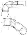
- Figure 7 is a perspective view of one half of the core and part of the pipe elbow; the core half is in the moulding position.
- Figure 8 is a side elevation view, partly in section, of the elbow and of the core in the same position as illustrated in Figure 7.
- Figure 9 is a perspective view of one half of the core and part of the pipe elbow; the core half is in an intermediate removal position.
- Figure 10 is a side elevation view, partly in section, of the elbow, and of the core in the same position as in Figure 9.
- Figure 11 is a perspective view of one half of the core and part of the pipe elbow; the core half is in a second subsequent removal position.
- Figure 12 is a side elevation view, partly in section, of the elbow and of the core in the same position as in Figure 11.
- the core rear, centre and inner body members have been illustrated in simplified form, to facilitate the understanding thereof.
- the core of the invention is for moulding elbows 2.
- These elbows have a centre portion having an internal doughnut shaped surface 4, i.e. a surface defined by the rotation of a circumference around an axis which lies in the same plane as the circumference and which is external thereto.
- the said elbows 2 have end portions 6 having a cylindrical internal surface, the right section of which is circular and which define respective ideal axes 7 ( Figure 8).
- the end regions 6 preferably have a larger internal diameter than that of the circumference generating the doughnut-shaped surface and consequently form seats situated in the ends of the elbow 2.
- the circular ends 8 of the end seat regions 6 are preferably located on respective mutually perpendicular planes, which implies that the arc of the elbow 2 is 90°.
- the drawing figures relate to these cases.
- the core of the invention comprises two halves, one of which is shown in the drawing. Each half has a flat circular end surface 10 (Figure 7), the diameter of which is obviously equal to that of the circle defined by the internal doughnut-shaped surface 2. These two end surfaces may be juxtaposed, such that both core halves 2 are arranged symmetrically to the plane of the flat end surfaces 10 in the juxtaposed position.
- the moulding operation may start and in the specification and claims, this position is called the core active position.
- Each half of a core comprises a core rear body member 12, two core centre body members 14 and a core inner body member 16.
- Each of these body members may be formed by one or more parts duly coupled together.
- the core rear body member 12 is formed with a first inner flat surface 18 which in the core active position is disposed parallel to the ideal axis 7. Extending from the said flat surface 18 there is a polyhedral, preferably central projection 20, having on the front thereof a second flat surface 22, parallel to the first flat surface 18. At the sides thereof, the polyhedral projection 20 is bounded by two first side surfaces 24 which preferably converge upwardly.
- the said first side surfaces 24 are also preferably provided with first longitudinal strips 26 which are either sunken into or extend outwardly from the immediate region of the corresponding first surface 24.
- the second flat surface 22 is provided with a third longitudinal strip 28 which is also sunken or outwardly projected relative to the immediate region of the second surface 22.
- these first 26 and third 28 strips are respectively at a level different from the corresponding immediate region of the first surface 24 or of the second flat surface 22.
- the first 26 and third 20 strips are formed by T-shaped guides, of which the free end of the central portion thereof is attached in the bottom of the slots illustrated as open U-shaped slots, while the arms thereof jut out above the respective first side surfaces 24 and second flat surface 22. Further reference will be made thereto hereinafter.
- the core rear body member 12 is also provided with a first external curved surface having a doughnut-shaped portion 30 and a cylindrical portion 32 ( Figure 7) and which are for providing the internal doughnut-shaped surface 4 and the end regions 6 of the elbow 2 having a cylindrical inner surface.
- Figures 1, 2 and 4 show a preferred embodiment of the invention.
- the core rear body member 12 is provided with a cylindrically shaped throttled portion 34, the diameter of which is less than that of the cylindrical portion 32.
- This throttled portion allows for the fitting of a collar member 36 (Figure 3), the outer side form of which is adapted for the moulding of the seats 6 situated at the ends of the elbow 2. It will be understood that by changing the collar member 36, one same core is made suitable for providing different seats.
- Figures 7, 9 and 11 show a core rear body member 12 not having the collar member and throttled portion, although in these cases also seats may be moulded in the elbow 2.
- the core rear body member 12 is formed also with a first upper surface 38 which in the core active position is comprised in the flat circular end surface 10.
- the core rear body member 12 as such, i.e. the body member whose outer surfaces take part, together with the mould surface, in the moulding of the elbow, has been described in the foregoing paragraphs. Nevertheless, for operation thereof (the same as with the other core body members) there is contemplated the existence of a handling portion 40, preferably integral with the body member 12. This may be attached to not shown control means and, to such end, is provided with a cavity 42 for the attachment of said control means. The operation of the body member 12 will be referred to again hereinafter.
- the outer surface of the handling portion 40 does not take part in the shaping of the elbow and, therefore, many varied shapes may be adopted. Nevertheless, it preferably has a portion having a cylindrical curved outer surface, as a continuation of the cylindrical portion 32. It is also preferably provided with a flat surface coplanar with the first flat surface 18, as well as a continuation of the polyhedral projection 20. It is, furthermore, provided with a step 44 defined between the said first flat surface 18 and a surface 46 coplanar with the said second flat surface 22.
- each central body member 14 is formed with a second side surface 48 which may engage one of the first side surfaces 24 of the polyhedral projection 20 and slide along this surface 24. So that this sliding may occur appropriately, each side face 24 is preferably provided with a second strip 50 which is either sunken into or extended from the immediate region of the corresponding second side surface 48.
- Figure 5 shows strips 50 in the form of a T-shaped slot, in which the outwardly extending arms of the T-shaped guides, previously referred to, may slide. Adjacent the said T-shaped strip, there is a discharge surface 51, which facilitates the movements of the core centre body members 14, which will be referred to hereinafter.
- Each core centre body member 14 is also provided with a second internal surface 52 which in the core active position engages the first internal flat surface 18 of the core rear body member 12. Opposite thereto, it is provided with a flat front surface 54 which in the said active position is flush with the second flat surface 22 of the polyhedral projection 20. It is also provided with a second end curved surface, in which there is to be appreciated a doughnut-shaped portion 56 and a cylindrical portion 58 which are a continuation of the doughnut-shaped portion 30 and cylindrical portion 32 of the core rear body member 12. At the upper end thereof there is a second upper surface 60, also comprised in the end circular flat surface 10.
- the core inner body member 16 is formed with a third internal surface 62 ( Figures 6 and 11). This third surface 62 may slidingly engage the second flat surface 22 of the polyhedral projection 20. Similar to what was described for the second side surface 48 of the core centre body members 14, the third surface 62 is provided with a fourth strip 64 which is either sunken into or extended outwardly from the immediate region of the third internal surface 62.
- Figure 6 shows a strip 64 in form of a T-shaped slot and, like previously, the outwardly extending arms of the T-shaped guides, previously mentioned, may slide in the slot.
- the core inner body member 16 is provided with a third curved surface having a doughnut-shaped portion 66 and a cylindrical portion 68 which respectively for a continuation of the doughnut-shaped portions 30 and 56 and of the cylindrical portions 32 and 56 of the core rear 12 and centre 14 body members. At the top thereof, there is a third upper surface 70 which in the core active position forms part of the circular flat surface 10.
- the core centre 14 and inner 16 body members may have throttled portions in which there may be attached other collar members which, together with the collar member 36, allow the moulding of end seats, as described above.
- each of the core rear body members 12 may make a first movement in the direction of the corresponding axis 7.
- a new movement takes place which may comprise a first stage of movement in a direction perpendicular to that of said first movement, whereby the core half shown is disposed as shown in Figures 9 and 10.
- this stage of movement causes the core inner member 16 also to lose contact with the inner surface of the elbow 2.
- a further movement stage takes place in the same direction as the first movement, which leads to complete withdrawal of the core from the elbow 2. Opening of the mould allows the elbow to be removed. Obviously, a single oblique movement resulting from these two stages may also take place.
Landscapes
- Engineering & Computer Science (AREA)
- Mechanical Engineering (AREA)
- Manufacturing & Machinery (AREA)
- Moulds For Moulding Plastics Or The Like (AREA)
- Molds, Cores, And Manufacturing Methods Thereof (AREA)
- Bending Of Plates, Rods, And Pipes (AREA)
Applications Claiming Priority (2)
| Application Number | Priority Date | Filing Date | Title |
|---|---|---|---|
| ES9700039A ES2147482B1 (es) | 1997-01-10 | 1997-01-10 | Noyo para moldeado de un codo en el interior de un molde y procedimiento para dicho moldeado. |
| ES9700039 | 1997-01-10 |
Publications (1)
| Publication Number | Publication Date |
|---|---|
| EP0852993A1 true EP0852993A1 (de) | 1998-07-15 |
Family
ID=8297827
Family Applications (1)
| Application Number | Title | Priority Date | Filing Date |
|---|---|---|---|
| EP98500002A Ceased EP0852993A1 (de) | 1997-01-10 | 1998-01-05 | Kern zum Formen eines bogenformigen Hohlkörpers in einer Form und Formverfahren |
Country Status (2)
| Country | Link |
|---|---|
| EP (1) | EP0852993A1 (de) |
| ES (1) | ES2147482B1 (de) |
Cited By (3)
| Publication number | Priority date | Publication date | Assignee | Title |
|---|---|---|---|---|
| EP1578584A4 (de) * | 2002-11-12 | 2008-07-30 | Entegris Inc | Verfahren und vorrichtung zum formen von polymeranschlussteilen |
| EP1867458A4 (de) * | 2005-04-07 | 2009-09-02 | Calsonic Kansei Corp | Harzspritzgiessvorrichtung und zylindrisches harzteil |
| CN115383984A (zh) * | 2022-07-21 | 2022-11-25 | 江苏开沃汽车有限公司 | 一种90°弯管注塑模芯模结构及其脱模方法 |
Citations (6)
| Publication number | Priority date | Publication date | Assignee | Title |
|---|---|---|---|---|
| DE1177319B (de) * | 1959-09-17 | 1964-09-03 | Borge Johannes Ravn Christense | Form zur Herstellung von bogenfoermigen Hohlkoerpern |
| US3545718A (en) * | 1968-02-01 | 1970-12-08 | Continental Oil Co | Removable mold core |
| FR2167737A1 (en) * | 1972-01-07 | 1973-08-24 | Messerschmitt Rudolf Kg | Pipe bend moulding core - with wedged splitting planes |
| DE2238625A1 (de) * | 1972-08-05 | 1974-02-14 | Helmuth Dallmer | Kernform |
| EP0055993A1 (de) * | 1981-01-05 | 1982-07-14 | Wavin B.V. | Mehrteiliger Kern und Verfahren zur Herstellung eines geformten Gegenstandes |
| US5385705A (en) * | 1993-04-11 | 1995-01-31 | Malloy; Gary J. | Reusable core apparatus for a casting mold, and methods of utilizing same |
-
1997
- 1997-01-10 ES ES9700039A patent/ES2147482B1/es not_active Expired - Fee Related
-
1998
- 1998-01-05 EP EP98500002A patent/EP0852993A1/de not_active Ceased
Patent Citations (6)
| Publication number | Priority date | Publication date | Assignee | Title |
|---|---|---|---|---|
| DE1177319B (de) * | 1959-09-17 | 1964-09-03 | Borge Johannes Ravn Christense | Form zur Herstellung von bogenfoermigen Hohlkoerpern |
| US3545718A (en) * | 1968-02-01 | 1970-12-08 | Continental Oil Co | Removable mold core |
| FR2167737A1 (en) * | 1972-01-07 | 1973-08-24 | Messerschmitt Rudolf Kg | Pipe bend moulding core - with wedged splitting planes |
| DE2238625A1 (de) * | 1972-08-05 | 1974-02-14 | Helmuth Dallmer | Kernform |
| EP0055993A1 (de) * | 1981-01-05 | 1982-07-14 | Wavin B.V. | Mehrteiliger Kern und Verfahren zur Herstellung eines geformten Gegenstandes |
| US5385705A (en) * | 1993-04-11 | 1995-01-31 | Malloy; Gary J. | Reusable core apparatus for a casting mold, and methods of utilizing same |
Cited By (3)
| Publication number | Priority date | Publication date | Assignee | Title |
|---|---|---|---|---|
| EP1578584A4 (de) * | 2002-11-12 | 2008-07-30 | Entegris Inc | Verfahren und vorrichtung zum formen von polymeranschlussteilen |
| EP1867458A4 (de) * | 2005-04-07 | 2009-09-02 | Calsonic Kansei Corp | Harzspritzgiessvorrichtung und zylindrisches harzteil |
| CN115383984A (zh) * | 2022-07-21 | 2022-11-25 | 江苏开沃汽车有限公司 | 一种90°弯管注塑模芯模结构及其脱模方法 |
Also Published As
| Publication number | Publication date |
|---|---|
| ES2147482B1 (es) | 2001-05-01 |
| ES2147482A1 (es) | 2000-09-01 |
Similar Documents
| Publication | Publication Date | Title |
|---|---|---|
| US4552384A (en) | Molded-joint assembly | |
| US3987144A (en) | Method for the removal of a mold core from an injection molded plastic duct section | |
| US5988313A (en) | Earplug | |
| US4125246A (en) | Pivot assembly mold apparatus | |
| US5611706A (en) | Rubber waterproof plug | |
| US6260820B1 (en) | Valve with rotatable valve member and method for forming same | |
| NZ214747A (en) | Injection mold for manufacturing flanged objects without sideways movement of the outer mold half | |
| US4112979A (en) | End cap for pipes | |
| EP0852993A1 (de) | Kern zum Formen eines bogenformigen Hohlkörpers in einer Form und Formverfahren | |
| US20040159816A1 (en) | Method of manufacturing a throttle valve connection piece and a housing therefor | |
| US5804123A (en) | Method of making plastic part having parting line free O-ring groove for fluid outlet | |
| US4210620A (en) | Pivot assembly mold method | |
| US20040140670A1 (en) | Apparatus and method for manufacturing a socket end of a pipe part provided with a sealing ring | |
| GB2169844A (en) | Die with means for extracting curved core portion | |
| JPH08238681A (ja) | レンズバレルおよびその成形用金型 | |
| CA2407856A1 (en) | Hose molding device | |
| CZ20004002A3 (cs) | Forma pro použití v IS stroji | |
| JPS59214607A (ja) | 熱可塑性樹脂管の受口成形方法及び装置 | |
| JPS6336929B2 (de) | ||
| JPS63502525A (ja) | 一つの材料から射出成形可能な転がり軸受用保持器 | |
| CN113266498B (zh) | 热塑性弹性体波纹管道 | |
| JP2879074B2 (ja) | 中空製品の成形方法 | |
| JP2002303319A (ja) | ガイドローラーおよびその製造方法 | |
| JPS632763B2 (de) | ||
| JPS6031946A (ja) | 合成樹脂管体の拡径受口部成形方法 |
Legal Events
| Date | Code | Title | Description |
|---|---|---|---|
| PUAI | Public reference made under article 153(3) epc to a published international application that has entered the european phase |
Free format text: ORIGINAL CODE: 0009012 |
|
| AK | Designated contracting states |
Kind code of ref document: A1 Designated state(s): DE FR GB IT |
|
| AX | Request for extension of the european patent |
Free format text: AL;LT;LV;MK;RO;SI |
|
| 17P | Request for examination filed |
Effective date: 19980803 |
|
| AKX | Designation fees paid |
Free format text: DE FR GB IT |
|
| RBV | Designated contracting states (corrected) |
Designated state(s): DE FR GB IT |
|
| 17Q | First examination report despatched |
Effective date: 20000824 |
|
| GRAG | Despatch of communication of intention to grant |
Free format text: ORIGINAL CODE: EPIDOS AGRA |
|
| STAA | Information on the status of an ep patent application or granted ep patent |
Free format text: STATUS: THE APPLICATION HAS BEEN REFUSED |
|
| 18R | Application refused |
Effective date: 20010930 |