EP0853227A2 - Echangeur de chaleur - Google Patents
Echangeur de chaleur Download PDFInfo
- Publication number
- EP0853227A2 EP0853227A2 EP98100457A EP98100457A EP0853227A2 EP 0853227 A2 EP0853227 A2 EP 0853227A2 EP 98100457 A EP98100457 A EP 98100457A EP 98100457 A EP98100457 A EP 98100457A EP 0853227 A2 EP0853227 A2 EP 0853227A2
- Authority
- EP
- European Patent Office
- Prior art keywords
- tube
- flat portion
- burring
- beads
- brazing
- Prior art date
- Legal status (The legal status is an assumption and is not a legal conclusion. Google has not performed a legal analysis and makes no representation as to the accuracy of the status listed.)
- Withdrawn
Links
- 239000011324 bead Substances 0.000 claims abstract description 36
- 238000005219 brazing Methods 0.000 claims abstract description 34
- 230000037431 insertion Effects 0.000 claims abstract description 33
- 238000003780 insertion Methods 0.000 claims abstract description 33
- 239000000463 material Substances 0.000 description 5
- 229910000838 Al alloy Inorganic materials 0.000 description 2
- 230000000694 effects Effects 0.000 description 2
- 230000003247 decreasing effect Effects 0.000 description 1
- 230000002950 deficient Effects 0.000 description 1
- 230000000593 degrading effect Effects 0.000 description 1
- 238000010030 laminating Methods 0.000 description 1
- 238000005192 partition Methods 0.000 description 1
- 239000012779 reinforcing material Substances 0.000 description 1
- 238000005096 rolling process Methods 0.000 description 1
Images


Classifications
-
- F—MECHANICAL ENGINEERING; LIGHTING; HEATING; WEAPONS; BLASTING
- F28—HEAT EXCHANGE IN GENERAL
- F28D—HEAT-EXCHANGE APPARATUS, NOT PROVIDED FOR IN ANOTHER SUBCLASS, IN WHICH THE HEAT-EXCHANGE MEDIA DO NOT COME INTO DIRECT CONTACT
- F28D1/00—Heat-exchange apparatus having stationary conduit assemblies for one heat-exchange medium only, the media being in contact with different sides of the conduit wall, in which the other heat-exchange medium is a large body of fluid, e.g. domestic or motor car radiators
- F28D1/02—Heat-exchange apparatus having stationary conduit assemblies for one heat-exchange medium only, the media being in contact with different sides of the conduit wall, in which the other heat-exchange medium is a large body of fluid, e.g. domestic or motor car radiators with heat-exchange conduits immersed in the body of fluid
- F28D1/03—Heat-exchange apparatus having stationary conduit assemblies for one heat-exchange medium only, the media being in contact with different sides of the conduit wall, in which the other heat-exchange medium is a large body of fluid, e.g. domestic or motor car radiators with heat-exchange conduits immersed in the body of fluid with plate-like or laminated conduits
- F28D1/0391—Heat-exchange apparatus having stationary conduit assemblies for one heat-exchange medium only, the media being in contact with different sides of the conduit wall, in which the other heat-exchange medium is a large body of fluid, e.g. domestic or motor car radiators with heat-exchange conduits immersed in the body of fluid with plate-like or laminated conduits a single plate being bent to form one or more conduits
-
- F—MECHANICAL ENGINEERING; LIGHTING; HEATING; WEAPONS; BLASTING
- F28—HEAT EXCHANGE IN GENERAL
- F28F—DETAILS OF HEAT-EXCHANGE AND HEAT-TRANSFER APPARATUS, OF GENERAL APPLICATION
- F28F9/00—Casings; Header boxes; Auxiliary supports for elements; Auxiliary members within casings
- F28F9/02—Header boxes; End plates
- F28F9/04—Arrangements for sealing elements into header boxes or end plates
- F28F9/16—Arrangements for sealing elements into header boxes or end plates by permanent joints, e.g. by rolling
- F28F9/18—Arrangements for sealing elements into header boxes or end plates by permanent joints, e.g. by rolling by welding
- F28F9/182—Arrangements for sealing elements into header boxes or end plates by permanent joints, e.g. by rolling by welding the heat-exchange conduits having ends with a particular shape, e.g. deformed; the heat-exchange conduits or end plates having supplementary joining means, e.g. abutments
-
- F—MECHANICAL ENGINEERING; LIGHTING; HEATING; WEAPONS; BLASTING
- F28—HEAT EXCHANGE IN GENERAL
- F28F—DETAILS OF HEAT-EXCHANGE AND HEAT-TRANSFER APPARATUS, OF GENERAL APPLICATION
- F28F2275/00—Fastening; Joining
- F28F2275/04—Fastening; Joining by brazing
Definitions
- the invention relates to a heat exchanger having an improved brazing property between tubes with beads formed and tube insertion holes of header pipes.
- a conventionally known heat exchanger has a plurality of tubes laminated, ends of the respective tubes inserted into tube insertion holes of header pipes, and the tubes brazed with the edges of the tube insertion holes.
- a medium for heat exchange is meandered a plurality of times to flow between an inlet joint and an outlet joint, which are formed on the header pipes, through the tubes while performing heat exchange.
- the tube used in the heat exchanger is known to be produced by folding a thin plate made of aluminum alloy or the like or laminating the two plates and brazing both ends of the plate in the breadth direction.
- This tube has inward projections (hereinafter called “beads”) which are formed of bends on the plate produced by rolling. These beads serve as a reinforcing material to improve a pressure resistance of the tube by being brazed mutually or by being brazed with an opposed tube face to divide inside passages and also expand the heat conducting face against a medium to improve a heat exchanging efficiency.
- the beads may be formed to continue in the longitudinal direction of the tube, in the form of circle or ellipse.
- the header pipes used for the heat exchanger may be formed by forming a flat material of aluminum alloy into an annular tube or by assembling a header pipe material for an end plate and a tank plate from a radial direction.
- Tube insertion holes of the header pipe are formed when the header pipe material is pressed. And, they are shaped to correspond to the cross sectional shape of the tube and generally slightly larger than the outer periphery of the tube so that the tube can be inserted.
- a flat portion without the beads is formed at given portions of the tube (e.g., Japanese Patent Laid-Open Publication No. Hei 8-200977), or a protruded face (hereinafter called "burring") is broadly formed at the edge of the tube insertion hole.
- the tube is formed to have flat ends, the strength within the header pipe is lowered when it is brazed, and results in defectively brazing the tube and the header pipe. Therefore, the beads are also formed at the ends of the tube. Specifically, the flat portion is formed to locate between the adjacent beads with respect to the longitudinal direction of the tube.
- the heat exchanger disclosed in Japanese Patent Laid-Open Publication No. Hei 8-49995 has a large number of beads formed at a given pitch in the longitudinal direction of the tube, and the burring which is longer than the given pitch is formed, so that the brazing face between the burring and the flat portion located between the beads is secured.
- the heat exchanger disclosed in Japanese Patent Laid-Open Publication No. Hei 8-49995 has the beads on the burring, so that the burring is required to be formed longer than a required brazing width. But, forming a long burring is difficult and also limited because it involves draw forming of the header pipe material.
- the invention relates to a heat exchanger, which is formed by inserting ends of a tube having long beads formed to divide inside passages into tube insertion holes of header pipes and brazing the tube with edges of the tube insertion holes, wherein a flat portion without the beads is formed on the ends of the tube, a burring is formed on the edges of the tube insertion holes so to be brazed in contact with the flat portion, and the flat portion is formed to have a width in a longitudinal direction of the tube, the width being larger than that of the burring in the longitudinal direction of the tube.
- the strength of the tube in the header pipes can be secured while brazing, defective brazing can be decreased, and even if the inserted degree of the tube is deviated to some extent, a brazing area can be secured.
- a brazing property can be improved, and a pressure resistance involved can also be improved.
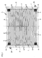
- a heat exchanger 1 of the invention has a plurality of tubes 2, 2, which are stacked with fins 5, 5 intervened between them, connected to communicate with a pair of header tubes 3, 4 which are disposed on both ends of the tubes 2, 2.
- the respective header pipes 3, 4 have upper and lower end openings closed by a blind cap 6 and their interior divided by partition plates 7 disposed at given locations. Besides, the header pipes are provided with an inlet joint 3a to receive a heat exchange medium and an output joint 4a to discharge the heat exchange medium outside.
- the header pipes 3, 4 are formed into a cylindrical tube having a circular cross section. And, tube insertion holes 9 are formed in a longitudinal direction of the header pipes 3, 4 at predetermined intervals.
- the tubes 2 have their ends brazed into the tube insertion holes 9.
- a side plate 8 is disposed at the top and bottom of the layer of the tubes 2, 2. The side plate 8 has its ends fixed to the header pipes 3, 4 and reinforces a structural strength of the heat exchanger.
- the heat exchange medium taken through the inlet joint 3a is meandered a plurality of times to flow between the header pipes 3, 4 in a unit of a given group of tubes 2, 2, passed through the tubes 2, 2 while heat-exchanging, and discharged from the outlet joint 4a. And, the heat exchange by the medium is promoted by the heat conduction by the fins 5, 5 intervened between the tubes 2, 2 and the side plate 8.
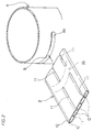
- Fig. 2 is a perspective view showing the neighborhood of the end of the tube 2 and the tube insertion hole 9.
- the tube 2 and the header pipe 4 (or header pipe 3) are connected to communicate mutually by inserting the end of the tube 2 into the tube insertion hole 9 (in the direction of an arrow in the drawing) and brazing a flat portion 2a of the tube 2 and a burring 9a of the tube insertion hole 9.
- the tube 2 is made of a plate (brazing sheet) having a brazing material claded on its inner face. Specifically, the tube 2 is formed into a flat shape having flat faces to face each other by forming joint sections 10, 10 at both ends in the breadth direction of the plate, and folding the plate at the center so to contact the joint sections 10, 10 mutually.
- a plurality of beads 11, 11 are formed to continue on the flat faces and in the longitudinal direction of the tube 2, and a plurality of passages 12, 12 are formed by being divided by the beads 11, 11 inside the tube 2. Tops of the beads 11, 11 are brazed to the opposed inner face of the flat face.
- the flat portion 2a is formed on a part of the tube 2 where the beads 11, 11 are not formed as indicated by chain lines. In this embodiment, it is formed by pressing back the beads which were once formed on the pertinent position.
- the beads 11, 11 are formed at the middle and ends of the tube 2. And, the flat portion 2a is formed between the beads 11, 11 in the longitudinal direction of the tube 2.
- the flat portion 2a is formed to have a width in the longitudinal direction of the tube 2 and larger than the width of a portion to contact with the burring 9a as described afterward.
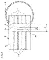
- Fig. 3 is a cross-sectional view showing a state that one end of the tube 2 is inserted into the tube insertion hole 9 and the flat portion 2a is aligned in contact with the burring 9a.
- the flat portion 2a and the burring 9a are mutually brazed in this state.
- the burring 9a is formed into an arc to protrude from the end of the tube insertion hole 9 inwardly of the header pipe 4.
- the flat portion 2a is formed to have a width large enough to accommodate the entire face of the burring and also its width is wider in the longitudinal direction of the tube. Specifically, a given interval is formed in the breadth direction of the tube 2 between the burring 9a and the beads 11, 11 and at the center and ends of the tube 2, and the flat portion 2a is positioned on the interval.
- the tube 2 Since the beads 11, 11 are also formed at the ends of the tube 2, the tube 2 has its strength secured within the header pipe 4. Especially, it is not deformed by heat during brazing, and brazing property between the flat portion 2a and the burring 9a is improved.
- Fig. 4 is a vertical sectional view showing a state that the flat portion 2a is aligned with the burring 9a.
- A indicates a width of the flat portion 2a in the longitudinal direction of the tube 2
- B a width of the burring 9a in the longitudinal direction of the tube 2.
- the width A of the flat portion 2a is larger than the width B of the burring 9a, so that a brazing area between the tube 2 and the header pipe 4 (header pipe 3) can be secured sufficiently. Therefore, even if an insertion degree of the end of the tube 2 is deviated, the brazing property can be improved, and the pressure resistance of the heat exchanger can be improved accordingly.
- the heat exchanger of this embodiment has a simplified shape of the flat portion 2a so that it can be formed with ease as shown in Fig. 5.
- the flat portion 2a of the first embodiment has boundaries with the same curvature as the burring 9a, but the flat portion 2a of this embodiment has linear boundaries. Since other structures are the same as in the first embodiment, their description is omitted.
- A is a width of the flat portion 2a
- B is a width of the burring 9a.
- the flat portion is formed into a rectangular shape having the width A with respect to the arc-shaped burring brazing section, so that the flat portion can be formed simply and easily.
- the invention relates to a heat exchanger which is formed by inserting ends of a tube having long beads formed to divide inside passages into tube insertion holes of header pipes and brazing the tube with edges of the tube insertion holes, wherein a flat portion without the beads is formed on the ends of the tube, a burring is formed on the edges of the tube insertion holes so to be brazed in contact with the flat portion, and the flat portion is formed to have a width in the longitudinal direction of the tube, which is larger than that of the burring in the longitudinal direction of the tube.
- the tube's strength in the header pipe can be secured, and the brazing area can be secured even if the insertion degree of the tube is deviated to some extent.
- the brazing property can be improved, and the pressure resistance involved can be improved.
Landscapes
- Engineering & Computer Science (AREA)
- Physics & Mathematics (AREA)
- Thermal Sciences (AREA)
- Mechanical Engineering (AREA)
- General Engineering & Computer Science (AREA)
- Details Of Heat-Exchange And Heat-Transfer (AREA)
- Heat-Exchange Devices With Radiators And Conduit Assemblies (AREA)
Applications Claiming Priority (2)
| Application Number | Priority Date | Filing Date | Title |
|---|---|---|---|
| JP4833/97 | 1997-01-14 | ||
| JP9004833A JPH10206079A (ja) | 1997-01-14 | 1997-01-14 | 熱交換器 |
Publications (2)
| Publication Number | Publication Date |
|---|---|
| EP0853227A2 true EP0853227A2 (fr) | 1998-07-15 |
| EP0853227A3 EP0853227A3 (fr) | 1999-03-24 |
Family
ID=11594706
Family Applications (1)
| Application Number | Title | Priority Date | Filing Date |
|---|---|---|---|
| EP98100457A Withdrawn EP0853227A3 (fr) | 1997-01-14 | 1998-01-13 | Echangeur de chaleur |
Country Status (3)
| Country | Link |
|---|---|
| EP (1) | EP0853227A3 (fr) |
| JP (1) | JPH10206079A (fr) |
| KR (1) | KR19980070184A (fr) |
Cited By (4)
| Publication number | Priority date | Publication date | Assignee | Title |
|---|---|---|---|---|
| EP1132706A3 (fr) * | 2000-03-06 | 2003-03-19 | Mitsubishi Heavy Industries, Ltd. | Echangeur de chaleur |
| CN103600149A (zh) * | 2013-11-15 | 2014-02-26 | 沈阳黎明航空发动机(集团)有限责任公司 | 一种薄壁导管换热器的钎焊方法 |
| CN112682500A (zh) * | 2020-12-31 | 2021-04-20 | 南宁市安和机械设备有限公司 | 一种采用错位打点油冷器管制成的油冷器 |
| DE112016002244B4 (de) | 2015-05-19 | 2023-11-02 | Sanden Corporation | Wärmetauscher und Herstellungsverfahren hierfür |
Families Citing this family (2)
| Publication number | Priority date | Publication date | Assignee | Title |
|---|---|---|---|---|
| JP2007278613A (ja) * | 2006-04-07 | 2007-10-25 | Calsonic Kansei Corp | オイルクーラ内蔵ラジエータ |
| KR100737142B1 (ko) * | 2006-06-07 | 2007-07-06 | 주식회사 두원공조 | 열교환기의 헤더 구조 |
Citations (2)
| Publication number | Priority date | Publication date | Assignee | Title |
|---|---|---|---|---|
| JPH0849995A (ja) | 1994-08-08 | 1996-02-20 | Calsonic Corp | 熱交換器 |
| JPH08200977A (ja) | 1995-01-27 | 1996-08-09 | Zexel Corp | 熱交換器用偏平チューブ及びその製造方法 |
Family Cites Families (4)
| Publication number | Priority date | Publication date | Assignee | Title |
|---|---|---|---|---|
| US5092398A (en) * | 1989-02-17 | 1992-03-03 | Zexel Corporation | Automotive parallel flow type heat exchanger |
| JP3146442B2 (ja) * | 1992-11-27 | 2001-03-19 | 株式会社ゼクセルヴァレオクライメートコントロール | 熱交換器用チューブおよびその製造方法 |
| JP3329906B2 (ja) * | 1993-10-29 | 2002-09-30 | 株式会社ゼクセルヴァレオクライメートコントロール | 熱交換器の偏平チューブ |
| KR100261006B1 (ko) * | 1996-07-03 | 2000-07-01 | 오타 유다카 | 열교환기용 편평튜우브 |
-
1997
- 1997-01-14 JP JP9004833A patent/JPH10206079A/ja active Pending
- 1997-12-19 KR KR1019970070881A patent/KR19980070184A/ko not_active Abandoned
-
1998
- 1998-01-13 EP EP98100457A patent/EP0853227A3/fr not_active Withdrawn
Patent Citations (2)
| Publication number | Priority date | Publication date | Assignee | Title |
|---|---|---|---|---|
| JPH0849995A (ja) | 1994-08-08 | 1996-02-20 | Calsonic Corp | 熱交換器 |
| JPH08200977A (ja) | 1995-01-27 | 1996-08-09 | Zexel Corp | 熱交換器用偏平チューブ及びその製造方法 |
Cited By (5)
| Publication number | Priority date | Publication date | Assignee | Title |
|---|---|---|---|---|
| EP1132706A3 (fr) * | 2000-03-06 | 2003-03-19 | Mitsubishi Heavy Industries, Ltd. | Echangeur de chaleur |
| CN103600149A (zh) * | 2013-11-15 | 2014-02-26 | 沈阳黎明航空发动机(集团)有限责任公司 | 一种薄壁导管换热器的钎焊方法 |
| CN103600149B (zh) * | 2013-11-15 | 2015-11-18 | 沈阳黎明航空发动机(集团)有限责任公司 | 一种薄壁导管换热器的钎焊方法 |
| DE112016002244B4 (de) | 2015-05-19 | 2023-11-02 | Sanden Corporation | Wärmetauscher und Herstellungsverfahren hierfür |
| CN112682500A (zh) * | 2020-12-31 | 2021-04-20 | 南宁市安和机械设备有限公司 | 一种采用错位打点油冷器管制成的油冷器 |
Also Published As
| Publication number | Publication date |
|---|---|
| EP0853227A3 (fr) | 1999-03-24 |
| JPH10206079A (ja) | 1998-08-07 |
| KR19980070184A (ko) | 1998-10-26 |
Similar Documents
| Publication | Publication Date | Title |
|---|---|---|
| US5123483A (en) | Heat exchanger | |
| US5186250A (en) | Tube for heat exchangers and a method for manufacturing the tube | |
| JP4171760B2 (ja) | 偏平管および偏平管の製造方法 | |
| KR100282585B1 (ko) | 열교환기용 냉매 유통관 및 그 제조방법 | |
| EP0584806B1 (fr) | Echangeur de chaleur à plaques et procédé pour sa fabrication | |
| US4730669A (en) | Heat exchanger core construction utilizing a diamond-shaped tube-to-header joint configuration | |
| US6453988B1 (en) | Heat exchanger and dimple tube used in the same, the tube having larger opposed protrusions closest to each end of tube | |
| US6073688A (en) | Flat tubes for heat exchanger | |
| EP0854343B1 (fr) | Echangeur de chaleur et sa méthode de fabrication | |
| US5868198A (en) | Header pipes for heat exchanger | |
| EP1362649A1 (fr) | Procédé et dispositif de pliage d'une bande métallique | |
| CN101663554B (zh) | 热交换器的构造 | |
| KR100254329B1 (ko) | 열교환기 | |
| EP0853227A2 (fr) | Echangeur de chaleur | |
| KR100511380B1 (ko) | 험프형플레이트핀열교환기 | |
| JPH09250896A (ja) | 熱交換器 | |
| EP1027942A1 (fr) | Tube pour echangeur de chaleur et procede de fabrication dudit tube | |
| EP0866301A1 (fr) | Echangeur de chaleur et son procede de fabrication | |
| JPH0722620Y2 (ja) | 空気調和機用アルミニウム製凝縮器 | |
| US11340027B2 (en) | Tube for a heat exchanger, and method of making the same | |
| US10801781B2 (en) | Compliant b-tube for radiator applications | |
| JP2000161888A (ja) | 熱交換器 | |
| JPH08178569A (ja) | 熱交換器用冷媒流通管の製造方法 | |
| JP2518952Y2 (ja) | 熱交換器 | |
| JP2551906Y2 (ja) | 熱交換器 |
Legal Events
| Date | Code | Title | Description |
|---|---|---|---|
| PUAI | Public reference made under article 153(3) epc to a published international application that has entered the european phase |
Free format text: ORIGINAL CODE: 0009012 |
|
| 17P | Request for examination filed |
Effective date: 19980113 |
|
| AK | Designated contracting states |
Kind code of ref document: A2 Designated state(s): DE ES FR GB |
|
| AX | Request for extension of the european patent |
Free format text: AL;LT;LV;MK;RO;SI |
|
| PUAL | Search report despatched |
Free format text: ORIGINAL CODE: 0009013 |
|
| AK | Designated contracting states |
Kind code of ref document: A3 Designated state(s): AT BE CH DE DK ES FI FR GB GR IE IT LI LU MC NL PT SE |
|
| AX | Request for extension of the european patent |
Free format text: AL;LT;LV;MK;RO;SI |
|
| AKX | Designation fees paid |
Free format text: DE ES FR GB |
|
| STAA | Information on the status of an ep patent application or granted ep patent |
Free format text: STATUS: THE APPLICATION HAS BEEN WITHDRAWN |
|
| 18W | Application withdrawn |
Withdrawal date: 19991228 |