EP0853377A2 - Vierphasen Phasenwandler - Google Patents
Vierphasen Phasenwandler Download PDFInfo
- Publication number
- EP0853377A2 EP0853377A2 EP97122206A EP97122206A EP0853377A2 EP 0853377 A2 EP0853377 A2 EP 0853377A2 EP 97122206 A EP97122206 A EP 97122206A EP 97122206 A EP97122206 A EP 97122206A EP 0853377 A2 EP0853377 A2 EP 0853377A2
- Authority
- EP
- European Patent Office
- Prior art keywords
- phase
- signal output
- hand end
- hand
- transmission line
- Prior art date
- Legal status (The legal status is an assumption and is not a legal conclusion. Google has not performed a legal analysis and makes no representation as to the accuracy of the status listed.)
- Granted
Links
Images

Classifications
-
- H—ELECTRICITY
- H01—ELECTRIC ELEMENTS
- H01P—WAVEGUIDES; RESONATORS, LINES, OR OTHER DEVICES OF THE WAVEGUIDE TYPE
- H01P1/00—Auxiliary devices
- H01P1/18—Phase-shifters
- H01P1/184—Strip line phase-shifters
Definitions
- the present invention relates to four-phase phase converters, and more particularly, to a four-phase phase converter used for QPSK modulation.
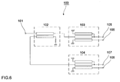
- Fig. 6 shows a conventional four-phase phase converter.
- a four-phase phase converter 100 includes a signal input terminal 101, a directive coupler 102 connected to the signal input terminal, unbalanced- to-balanced converters 103 and 104 connected to two outputs of the directive coupler 102, and signal output terminals 105, 106, 107, and 108 connected to two outputs of each of the unbalanced-to-balanced converters 103 and 104.
- the directive coupler 102, and the unbalanced-to- balanced converters 103 and 104 are formed of a combination of ⁇ /4 microstriplines. Since their configurations are of general types, the descriptions thereof will be omitted.
- a signal input to the signal input terminal 101 is converted to two signals having phases 90 degrees apart in the directive coupler 102, and they are input to the unbalanced-to-balanced converters 103 and 104.
- Each of the signals input to the unbalanced-to- balanced converters 103 and 104 is converted to two signals having phases 180 degrees apart and output from the signal output terminals 105, 106, 107, and 108.
- one signal is divided into four signals having phases 90 degrees different from each other.
- one directive coupler and two unbalanced-to-balanced converters namely, three phase shifters are required to obtain one four-phase phase converter. Since this requires an area for forming eight microstriplines and certain clearances between the phase shifters in order to avoid coupling between the phase shifters, the required area is large and therefore the cost increases. In addition, an assembling cost for assembling each phase shifter is also necessary. Furthermore, since the directive coupler and the unbalanced-to-balanced converters are manufactured independently, phase deviation caused in assembling becomes large.
- the object of the present invention is achieved in one aspect of the present invention through the provision of a four-phase phase converter including first, second, third, and fourth transmission lines sequentially disposed in parallel to couple with each other, wherein the length of the coupling sections of the first, second, third, and fourth transmission lines is set to one fourth the wavelength of the signal to be used at its frequency; and among the ends of the first, second, third, and fourth transmission lines, one end serves as a signal input end, four ends serve as signal output ends, two ends are connected to the ground, and the other one end is connected to one of the four signal output ends.
- the four-phase phase converter may be configured such that the left-hand end of the third transmission line serves as a signal input end; the left-hand ends of the first and second transmission lines and the right- hand ends of the first and fourth transmission lines serve as signal output ends; the right-hand end of the second transmission line and the left-hand end of the fourth transmission line are grounded; and the right-hand end of the third transmission line is connected to the right-hand end of the first transmission line.
- the four-phase phase converter may also be configured such that the left-hand end of the second transmission line serves as a signal input end; the left- hand ends of the third and fourth transmission lines and the right-hand ends of the first and second transmission lines serve as signal output ends; the left-hand end of the first transmission line and the right-hand end of the fourth transmission line are grounded; and the right-hand end of the third transmission line is connected to the right-hand end of the second transmission line.
- the object of the present invention is achieved in another aspect of the present invention through the provision of a four-phase phase converter including first, second, third, and fourth transmission lines sequentially disposed in parallel in the horizontal direction to couple with each other; wherein the length of the coupling sections of the first, second, third, and fourth transmission lines is set to one fourth the wavelength of the signal to be used at its frequency; and among the ends of the first, second, third, and fourth transmission lines, one end serves as a signal input end, four ends serve as signal output ends, one end is connected to the ground, and the other two ends are connected to two of the four signal output ends.
- the four-phase phase converter may be configured such that the left-hand end of the first transmission line serves as a signal input end; the left-hand ends of the second and fourth transmission lines and the right- hand ends of the first and second transmission lines serve as signal output ends; the right-hand end of the third transmission line is grounded; and the left-hand end of the third transmission line is connected to the left-hand end of the second transmission line, and the right-hand end of the fourth transmission line is connected to the right-hand end of the first transmission line.
- a four-phase phase converter of the present invention since four ⁇ /4 transmission lines are arranged such that they are coupled with each other, and among the eight ends thereof, one end is used as an input end, four ends are used as output ends, and the other ends are grounded or connected to an output end, an inexpensive four-phase phase converter requiring a small area and a small phase variation is obtained.
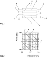
- Fig. 1 shows a four-phase phase converter according to an embodiment of the present invention.
- Fig. 2 shows a phase characteristic of the four- phase phase converter shown in Fig. 1.
- Fig. 3 shows a four-phase phase converter according to another embodiment of the present invention.
- Fig. 4 shows a four-phase phase converter according to still another embodiment of the present invention.
- Fig. 5 is a perspective view of a four-phase phase converter according to yet another embodiment of the present invention.
- Fig. 6 shows a conventional four-phase phase converter.
- Fig. 1 shows a four-phase phase converter according to an embodiment of the present invention.
- a four-phase phase converter 1 includes microstriplines 2, 3, 4, and 5 serving as first, second, third, and fourth transmission lines disposed close such that they are coupled with each other, a signal input terminal 6, and signal output terminals 7, 8, 9, and 10.
- the signal input terminal 6 is connected to the left-hand end of the third microstripline 4 serving as a signal input end
- the signal output terminal 7 is connected to the left-hand end of the second microstripline 3 serving as a first signal output end
- the signal output terminal 8 is connected to the left- hand end of the first microstripline 2 serving as a second signal output end
- the signal output terminal 9 is connected to the right-hand end of the first microstripline 2 serving as a third signal output end
- the signal output terminal 10 is connected to the right-hand end of the fourth microstripline 5 serving as a fourth signal output end.
- the right-hand ends of the first and third microstriplines 2 and 4 are connected to each other, and the right-hand end of the second microstripline 3 and the left-hand end of the fourth microstripline 5 are grounded.
- microstriplines 2, 3, 4, and 5 are set such that their length equals one fourth the wavelength of the signal to be used at its frequency.
- Fig. 2 is a graph indicating a phase characteristic of the four-phase phase converter 1 shown in Fig. 1.
- the horizontal axis indicates a frequency and the vertical axis indicates the phase shift of an output signal from the phase of the corresponding input signal.
- curve “a” indicates the phase shift of an signal output from the signal output terminal 7 from the phase of the corresponding input signal
- curve “b” indicates the phase shift of a signal output from the signal output terminal 8
- curve “c” indicates the phase shift of a signal output from the signal output terminal 9
- curve “d” indicates the phase shift of a signal output from the output signal terminal 10.
- the phases of the four outputs are different from each other by 90 degrees at 2.7 GHz, which is the frequency of the used signal, as shown in Fig. 2.
- Fig. 3 shows a four-phase phase converter according to another embodiment of the present invention.
- a four-phase phase converter 20 includes microstriplines 21, 22, 23, and 24 serving as first, second, third, and fourth transmission lines disposed close such that they are coupled with each other, a signal input terminal 25, and signal output terminals 26, 27, 28, and 29.
- the signal input terminal 25 is connected to the left-hand end of the second microstripline 22 serving as a signal input end
- the signal output terminal 26 is connected to the left-hand end of the third microstripline 23 serving as a first signal output end
- the signal output terminal 27 is connected to the left- hand end of the fourth microstripline 24 serving as a second signal output end
- the signal output terminal 28 is connected to the right-hand end of the first microstripline 21 serving as a third signal output end
- the signal output terminal 29 is connected to the right-hand end of the second microstripline 22 serving as a fourth signal output end.
- the right-hand ends of the second and third microstriplines 22 and 23 are connected to each other, and the left-hand end of the first microstripline 21 and the right-hand end of the fourth microstripline 24 are grounded.
- microstriplines 21, 22, 23, and 24 are set such that their length equals one fourth the wavelength of the signal to be used at its frequency.
- Fig. 4 shows a four-phase phase converter according to still another embodiment of the present invention.
- a four-phase phase converter 30 includes microstriplines 31, 32, 33, and 34 serving as first, second, third, and fourth transmission lines disposed close such that they are coupled with each other, a signal input terminal 35, and signal output terminals 36, 37, 38, and 39.
- the signal input terminal 35 is connected to the left-hand end of the first microstripline 31 serving as a signal input end
- the signal output terminal 36 is connected to the left-hand end of the second microstripline 32 serving as a first signal output end
- the signal output terminal 37 is connected to the left- hand end of the fourth microstripline 34 serving as a second signal output end
- the signal output terminal 38 is connected to the right-hand end of the first microstripline 31 serving as a third signal output end
- the signal output terminal 39 is connected to the right-hand end of the second microstripline 32 serving as a fourth signal output end.
- the left-hand ends of the second and third microstriplines 32 and 33 are connected to each other
- the right-hand ends of the first and fourth microstriplines 31 and 34 are connected to each other
- the right-hand end of the third microstripline 33 is grounded.
- microstriplines 31, 32, 33, and 34 are set such that their length equals one fourth the wavelength of the signal to be used at its frequency.
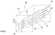
- Fig. 5 shows a four-phase phase converter according to yet another embodiment of the present invention.
- a four-phase phase converter 40 includes strip conductors 42, 43, 44, and 45 serving as first, second, third, and fourth transmission lines laminated with a dielectric 41 sandwiched therebetween to form a multilayer structure and disposed with appropriate gaps therebetween such that they are coupled with each other, a signal input terminal 46, and signal output terminals 47, 48, 49, and 50.
- the signal input terminal 46 is connected to the left-hand end of the third strip conductor 44 serving as a signal input end
- the signal output terminal 47 is connected to the left-hand end of the second strip conductor 43 serving as a first signal output end
- the signal output terminal 48 is connected to the left-hand end of the first strip conductor 42 serving as a second signal output end
- the signal output terminal 49 is connected to the right-hand end of the first strip conductor 42 serving as a third signal output end
- the signal output terminal 50 is connected to the right- hand end of the fourth strip conductor 45 serving as a fourth signal output end.
- the right-hand ends of the first and third strip conductors 42 and 44 are connected to each other, and the right-hand end of the second strip conductor 43 and the left-hand end of the fourth strip conductor 45 are grounded.
- the strip conductors 42, 43, 44, and 45 are set such that their length equals one fourth the wavelength of the signal to be used at its frequency.
- each transmission line in the four-phase phase converter 40 is the same as those in the four-phase phase converter 1 shown in Fig. 1.
- microstriplines and strip conductors are used as transmission lines. They may be formed in a curved shape such as a meander- shape or a spiral shape with the positional relationship between the four transmission lines being maintained. In the above embodiments, microstriplines and strip conductors are used. Other transmission lines such as strip lines and electrically conductive cables may be used, and the same advantages are obtained in that case.
Landscapes
- Waveguide Switches, Polarizers, And Phase Shifters (AREA)
- Superheterodyne Receivers (AREA)
- Digital Transmission Methods That Use Modulated Carrier Waves (AREA)
Applications Claiming Priority (6)
| Application Number | Priority Date | Filing Date | Title |
|---|---|---|---|
| JP335690/96 | 1996-12-16 | ||
| JP33569096 | 1996-12-16 | ||
| JP33569096 | 1996-12-16 | ||
| JP9326441A JPH10233813A (ja) | 1996-12-16 | 1997-11-27 | 4相位相変換器 |
| JP326441/97 | 1997-11-27 | ||
| JP32644197 | 1997-11-27 |
Publications (3)
| Publication Number | Publication Date |
|---|---|
| EP0853377A2 true EP0853377A2 (de) | 1998-07-15 |
| EP0853377A3 EP0853377A3 (de) | 2000-08-09 |
| EP0853377B1 EP0853377B1 (de) | 2003-02-05 |
Family
ID=26572186
Family Applications (1)
| Application Number | Title | Priority Date | Filing Date |
|---|---|---|---|
| EP97122206A Expired - Lifetime EP0853377B1 (de) | 1996-12-16 | 1997-12-16 | Vierphasen Phasenwandler |
Country Status (4)
| Country | Link |
|---|---|
| US (1) | US6066995A (de) |
| EP (1) | EP0853377B1 (de) |
| JP (1) | JPH10233813A (de) |
| DE (1) | DE69718890T2 (de) |
Cited By (3)
| Publication number | Priority date | Publication date | Assignee | Title |
|---|---|---|---|---|
| FR2790871A1 (fr) * | 1999-03-11 | 2000-09-15 | Cit Alcatel | Transformateur radiofrequence et son utilisation |
| WO2001020708A1 (de) * | 1999-09-14 | 2001-03-22 | Marconi Communications Gmbh | Symmetrierglied |
| EP3331092A4 (de) * | 2015-07-30 | 2019-04-10 | Mitsubishi Electric Corporation | Rückkopplungskreis |
Families Citing this family (2)
| Publication number | Priority date | Publication date | Assignee | Title |
|---|---|---|---|---|
| KR100531136B1 (ko) * | 2002-09-09 | 2005-11-28 | 주식회사에스지테크놀러지 | 직접 변환 수신기용 6포트 |
| TW201012102A (en) * | 2008-09-05 | 2010-03-16 | Asustek Comp Inc | Delay line for printed circuit broad |
Family Cites Families (5)
| Publication number | Priority date | Publication date | Assignee | Title |
|---|---|---|---|---|
| US3764941A (en) * | 1972-12-08 | 1973-10-09 | Ibm | Stripline directional coupling device |
| JPS59148405A (ja) * | 1983-02-14 | 1984-08-25 | Matsushita Electric Ind Co Ltd | 平衡不平衡変換器 |
| JPH02190003A (ja) * | 1989-01-19 | 1990-07-26 | Fujitsu Ltd | 位相反転器 |
| US5126704A (en) * | 1991-04-11 | 1992-06-30 | Harris Corporation | Polyphase divider/combiner |
| JP2651336B2 (ja) * | 1993-06-07 | 1997-09-10 | 株式会社エイ・ティ・アール光電波通信研究所 | 方向性結合器 |
-
1997
- 1997-11-27 JP JP9326441A patent/JPH10233813A/ja active Pending
- 1997-12-16 DE DE69718890T patent/DE69718890T2/de not_active Expired - Lifetime
- 1997-12-16 EP EP97122206A patent/EP0853377B1/de not_active Expired - Lifetime
- 1997-12-16 US US08/991,870 patent/US6066995A/en not_active Expired - Lifetime
Cited By (6)
| Publication number | Priority date | Publication date | Assignee | Title |
|---|---|---|---|---|
| FR2790871A1 (fr) * | 1999-03-11 | 2000-09-15 | Cit Alcatel | Transformateur radiofrequence et son utilisation |
| EP1037300A1 (de) * | 1999-03-11 | 2000-09-20 | Alcatel | Radiofrequenztransformator und seine Verwendung |
| US6600910B1 (en) | 1999-03-11 | 2003-07-29 | Alcatel | Radio frequency transformer and its use |
| WO2001020708A1 (de) * | 1999-09-14 | 2001-03-22 | Marconi Communications Gmbh | Symmetrierglied |
| US6714094B1 (en) | 1999-09-14 | 2004-03-30 | Marconi Communications Gmbh | Balun |
| EP3331092A4 (de) * | 2015-07-30 | 2019-04-10 | Mitsubishi Electric Corporation | Rückkopplungskreis |
Also Published As
| Publication number | Publication date |
|---|---|
| DE69718890T2 (de) | 2003-09-11 |
| US6066995A (en) | 2000-05-23 |
| JPH10233813A (ja) | 1998-09-02 |
| DE69718890D1 (de) | 2003-03-13 |
| EP0853377A3 (de) | 2000-08-09 |
| EP0853377B1 (de) | 2003-02-05 |
Similar Documents
| Publication | Publication Date | Title |
|---|---|---|
| US6040745A (en) | Unbalanced-to-balanced converter | |
| US7190240B2 (en) | Multi-section coupler assembly | |
| US7132906B2 (en) | Coupler having an uncoupled section | |
| CN1894823B (zh) | 双层耦合器 | |
| US5818308A (en) | Coupled line element | |
| US6278340B1 (en) | Miniaturized broadband balun transformer having broadside coupled lines | |
| JP2000506344A (ja) | 多層基板に設けられた高周波バルン | |
| US6346863B2 (en) | Directional coupler | |
| GB2210510A (en) | Microwave balun | |
| EP1032071B1 (de) | Breitbandige Symmetrierschaltung für drahtlose und hochfrequente Anwendungen | |
| EP1208615B1 (de) | Viertorhybrid | |
| US4823097A (en) | Microwave directional coupler | |
| WO2020157804A1 (ja) | 伝送線路及び移相器 | |
| WO2000019562A1 (fr) | Circuit d'alimentation d'antenne | |
| EP0853377B1 (de) | Vierphasen Phasenwandler | |
| US4577167A (en) | Microstrip line branching coupler having coaxial coupled remote termination | |
| US4093928A (en) | Microstrip hybrid ring coupler | |
| JPH0993008A (ja) | バトラーマトリクス回路とアンテナ装置 | |
| JPH09246817A (ja) | 高周波電力分配合成器 | |
| JP3293585B2 (ja) | 移相器 | |
| JP2002344213A (ja) | 方向性結合器 | |
| US5959509A (en) | Printed 180 degree differential phase shifter including a non-uniform non-regular line | |
| US7541886B2 (en) | NRD guide transition, and coupling structure of dielectric material and conductor | |
| JPH09214211A (ja) | 非接触形結合回路 | |
| JPH04119001A (ja) | 方向性結合器 |
Legal Events
| Date | Code | Title | Description |
|---|---|---|---|
| PUAI | Public reference made under article 153(3) epc to a published international application that has entered the european phase |
Free format text: ORIGINAL CODE: 0009012 |
|
| 17P | Request for examination filed |
Effective date: 19971216 |
|
| AK | Designated contracting states |
Kind code of ref document: A2 Designated state(s): DE GB SE |
|
| AX | Request for extension of the european patent |
Free format text: AL;LT;LV;MK;RO;SI |
|
| PUAL | Search report despatched |
Free format text: ORIGINAL CODE: 0009013 |
|
| AK | Designated contracting states |
Kind code of ref document: A3 Designated state(s): AT BE CH DE DK ES FI FR GB GR IE IT LI LU MC NL PT SE |
|
| AX | Request for extension of the european patent |
Free format text: AL;LT;LV;MK;RO;SI |
|
| RIC1 | Information provided on ipc code assigned before grant |
Free format text: 7H 01P 1/18 A |
|
| AKX | Designation fees paid |
Free format text: DE GB SE |
|
| GRAH | Despatch of communication of intention to grant a patent |
Free format text: ORIGINAL CODE: EPIDOS IGRA |
|
| GRAH | Despatch of communication of intention to grant a patent |
Free format text: ORIGINAL CODE: EPIDOS IGRA |
|
| GRAA | (expected) grant |
Free format text: ORIGINAL CODE: 0009210 |
|
| AK | Designated contracting states |
Designated state(s): DE GB SE |
|
| REG | Reference to a national code |
Ref country code: GB Ref legal event code: FG4D |
|
| REF | Corresponds to: |
Ref document number: 69718890 Country of ref document: DE Date of ref document: 20030313 Kind code of ref document: P |
|
| REG | Reference to a national code |
Ref country code: SE Ref legal event code: TRGR |
|
| PLBE | No opposition filed within time limit |
Free format text: ORIGINAL CODE: 0009261 |
|
| STAA | Information on the status of an ep patent application or granted ep patent |
Free format text: STATUS: NO OPPOSITION FILED WITHIN TIME LIMIT |
|
| 26N | No opposition filed |
Effective date: 20031106 |
|
| PGFP | Annual fee paid to national office [announced via postgrant information from national office to epo] |
Ref country code: GB Payment date: 20161222 Year of fee payment: 20 Ref country code: DE Payment date: 20161213 Year of fee payment: 20 |
|
| PGFP | Annual fee paid to national office [announced via postgrant information from national office to epo] |
Ref country code: SE Payment date: 20161221 Year of fee payment: 20 |
|
| REG | Reference to a national code |
Ref country code: DE Ref legal event code: R071 Ref document number: 69718890 Country of ref document: DE |
|
| REG | Reference to a national code |
Ref country code: GB Ref legal event code: PE20 Expiry date: 20171215 |
|
| REG | Reference to a national code |
Ref country code: SE Ref legal event code: EUG |
|
| PG25 | Lapsed in a contracting state [announced via postgrant information from national office to epo] |
Ref country code: GB Free format text: LAPSE BECAUSE OF EXPIRATION OF PROTECTION Effective date: 20171215 |