EP0853541B2 - Dispositif de blocage du reflux pour une unite d'injection d'une machine a mouler par injection - Google Patents
Dispositif de blocage du reflux pour une unite d'injection d'une machine a mouler par injectionInfo
- Publication number
- EP0853541B2 EP0853541B2 EP96932372A EP96932372A EP0853541B2 EP 0853541 B2 EP0853541 B2 EP 0853541B2 EP 96932372 A EP96932372 A EP 96932372A EP 96932372 A EP96932372 A EP 96932372A EP 0853541 B2 EP0853541 B2 EP 0853541B2
- Authority
- EP
- European Patent Office
- Prior art keywords
- blocking
- set forth
- screw tip
- base body
- bush
- Prior art date
- Legal status (The legal status is an assumption and is not a legal conclusion. Google has not performed a legal analysis and makes no representation as to the accuracy of the status listed.)
- Expired - Lifetime
Links
- 238000002347 injection Methods 0.000 title claims abstract description 5
- 239000007924 injection Substances 0.000 title claims abstract description 5
- 238000000465 moulding Methods 0.000 title 1
- 239000000463 material Substances 0.000 claims abstract description 63
- 230000000903 blocking effect Effects 0.000 claims abstract description 47
- 239000000654 additive Substances 0.000 claims abstract description 26
- 238000007789 sealing Methods 0.000 claims abstract description 20
- 239000010410 layer Substances 0.000 claims abstract description 16
- 229910052751 metal Inorganic materials 0.000 claims abstract description 11
- 239000002184 metal Substances 0.000 claims abstract description 11
- 150000001875 compounds Chemical class 0.000 claims abstract description 10
- 229910021332 silicide Inorganic materials 0.000 claims abstract description 7
- 239000011241 protective layer Substances 0.000 claims abstract description 6
- 238000001746 injection moulding Methods 0.000 claims abstract description 4
- 239000013078 crystal Substances 0.000 claims abstract description 3
- 230000000996 additive effect Effects 0.000 claims abstract 18
- 238000000034 method Methods 0.000 claims description 46
- 230000008569 process Effects 0.000 claims description 34
- XEEYBQQBJWHFJM-UHFFFAOYSA-N iron Substances [Fe] XEEYBQQBJWHFJM-UHFFFAOYSA-N 0.000 claims description 19
- 239000000945 filler Substances 0.000 claims description 18
- 229910001149 41xx steel Inorganic materials 0.000 claims description 13
- 229910052742 iron Inorganic materials 0.000 claims description 13
- 239000000203 mixture Substances 0.000 claims description 13
- PXHVJJICTQNCMI-UHFFFAOYSA-N nickel Substances [Ni] PXHVJJICTQNCMI-UHFFFAOYSA-N 0.000 claims description 13
- 229910052804 chromium Inorganic materials 0.000 claims description 10
- 150000001247 metal acetylides Chemical class 0.000 claims description 10
- 150000002739 metals Chemical class 0.000 claims description 10
- 229910052759 nickel Inorganic materials 0.000 claims description 10
- 239000000843 powder Substances 0.000 claims description 10
- 229910000831 Steel Inorganic materials 0.000 claims description 8
- 239000007789 gas Substances 0.000 claims description 8
- 229910052757 nitrogen Inorganic materials 0.000 claims description 8
- 239000010959 steel Substances 0.000 claims description 8
- 239000010936 titanium Substances 0.000 claims description 8
- 229910052721 tungsten Inorganic materials 0.000 claims description 8
- 229910052782 aluminium Inorganic materials 0.000 claims description 7
- 229910052799 carbon Inorganic materials 0.000 claims description 7
- 229910052735 hafnium Inorganic materials 0.000 claims description 7
- 229910052748 manganese Inorganic materials 0.000 claims description 7
- 238000002844 melting Methods 0.000 claims description 7
- 229910052750 molybdenum Inorganic materials 0.000 claims description 7
- 229910052758 niobium Inorganic materials 0.000 claims description 7
- 229910052710 silicon Inorganic materials 0.000 claims description 7
- 229910052715 tantalum Inorganic materials 0.000 claims description 7
- 150000003568 thioethers Chemical class 0.000 claims description 7
- 229910052719 titanium Inorganic materials 0.000 claims description 7
- 229910052720 vanadium Inorganic materials 0.000 claims description 7
- 229910052726 zirconium Inorganic materials 0.000 claims description 7
- 238000013532 laser treatment Methods 0.000 claims description 6
- 238000003754 machining Methods 0.000 claims description 6
- 239000000126 substance Substances 0.000 claims description 6
- VYZAMTAEIAYCRO-UHFFFAOYSA-N Chromium Chemical compound [Cr] VYZAMTAEIAYCRO-UHFFFAOYSA-N 0.000 claims description 5
- 229910052796 boron Inorganic materials 0.000 claims description 5
- 229910052791 calcium Inorganic materials 0.000 claims description 5
- 238000010438 heat treatment Methods 0.000 claims description 5
- XKRFYHLGVUSROY-UHFFFAOYSA-N Argon Chemical compound [Ar] XKRFYHLGVUSROY-UHFFFAOYSA-N 0.000 claims description 4
- 238000004519 manufacturing process Methods 0.000 claims description 4
- 150000004767 nitrides Chemical class 0.000 claims description 4
- 239000007787 solid Substances 0.000 claims description 4
- IJGRMHOSHXDMSA-UHFFFAOYSA-N Atomic nitrogen Chemical compound N#N IJGRMHOSHXDMSA-UHFFFAOYSA-N 0.000 claims description 3
- QVGXLLKOCUKJST-UHFFFAOYSA-N atomic oxygen Chemical compound [O] QVGXLLKOCUKJST-UHFFFAOYSA-N 0.000 claims description 3
- 239000000919 ceramic Substances 0.000 claims description 3
- 229910052760 oxygen Inorganic materials 0.000 claims description 3
- 239000001301 oxygen Substances 0.000 claims description 3
- 230000005855 radiation Effects 0.000 claims description 3
- BUGBHKTXTAQXES-UHFFFAOYSA-N Selenium Chemical compound [Se] BUGBHKTXTAQXES-UHFFFAOYSA-N 0.000 claims description 2
- NINIDFKCEFEMDL-UHFFFAOYSA-N Sulfur Chemical compound [S] NINIDFKCEFEMDL-UHFFFAOYSA-N 0.000 claims description 2
- 229910052786 argon Inorganic materials 0.000 claims description 2
- 229910010293 ceramic material Inorganic materials 0.000 claims description 2
- 238000000227 grinding Methods 0.000 claims description 2
- 239000011261 inert gas Substances 0.000 claims description 2
- 238000003801 milling Methods 0.000 claims description 2
- 229910052711 selenium Inorganic materials 0.000 claims description 2
- 239000011669 selenium Substances 0.000 claims description 2
- 229910052717 sulfur Inorganic materials 0.000 claims description 2
- 239000011593 sulfur Substances 0.000 claims description 2
- 229910052714 tellurium Inorganic materials 0.000 claims description 2
- PORWMNRCUJJQNO-UHFFFAOYSA-N tellurium atom Chemical compound [Te] PORWMNRCUJJQNO-UHFFFAOYSA-N 0.000 claims description 2
- 229910017052 cobalt Inorganic materials 0.000 claims 2
- 239000010941 cobalt Substances 0.000 claims 2
- GUTLYIVDDKVIGB-UHFFFAOYSA-N cobalt atom Chemical compound [Co] GUTLYIVDDKVIGB-UHFFFAOYSA-N 0.000 claims 2
- 238000003483 aging Methods 0.000 claims 1
- 238000000137 annealing Methods 0.000 claims 1
- 238000005520 cutting process Methods 0.000 claims 1
- 238000009826 distribution Methods 0.000 claims 1
- 239000007769 metal material Substances 0.000 claims 1
- 238000005496 tempering Methods 0.000 claims 1
- 230000004927 fusion Effects 0.000 abstract description 4
- UCKMPCXJQFINFW-UHFFFAOYSA-N Sulphide Chemical compound [S-2] UCKMPCXJQFINFW-UHFFFAOYSA-N 0.000 abstract 1
- FVBUAEGBCNSCDD-UHFFFAOYSA-N silicide(4-) Chemical compound [Si-4] FVBUAEGBCNSCDD-UHFFFAOYSA-N 0.000 abstract 1
- 238000000576 coating method Methods 0.000 description 15
- 239000011248 coating agent Substances 0.000 description 8
- 238000003466 welding Methods 0.000 description 8
- 239000011651 chromium Substances 0.000 description 7
- 230000033001 locomotion Effects 0.000 description 5
- 238000002156 mixing Methods 0.000 description 5
- 229910001566 austenite Inorganic materials 0.000 description 4
- 230000005496 eutectics Effects 0.000 description 4
- 229910000734 martensite Inorganic materials 0.000 description 4
- 230000004888 barrier function Effects 0.000 description 3
- 230000008018 melting Effects 0.000 description 3
- 238000005275 alloying Methods 0.000 description 2
- 238000005260 corrosion Methods 0.000 description 2
- 230000007797 corrosion Effects 0.000 description 2
- 238000010285 flame spraying Methods 0.000 description 2
- 239000000155 melt Substances 0.000 description 2
- 238000007711 solidification Methods 0.000 description 2
- 230000008023 solidification Effects 0.000 description 2
- 239000007921 spray Substances 0.000 description 2
- 230000009466 transformation Effects 0.000 description 2
- 238000000844 transformation Methods 0.000 description 2
- 238000011282 treatment Methods 0.000 description 2
- 229910000859 α-Fe Inorganic materials 0.000 description 2
- INZDTEICWPZYJM-UHFFFAOYSA-N 1-(chloromethyl)-4-[4-(chloromethyl)phenyl]benzene Chemical compound C1=CC(CCl)=CC=C1C1=CC=C(CCl)C=C1 INZDTEICWPZYJM-UHFFFAOYSA-N 0.000 description 1
- 241000370092 Actiniopteris Species 0.000 description 1
- 238000005299 abrasion Methods 0.000 description 1
- 230000009471 action Effects 0.000 description 1
- 229910045601 alloy Inorganic materials 0.000 description 1
- 239000000956 alloy Substances 0.000 description 1
- 238000002485 combustion reaction Methods 0.000 description 1
- 239000002131 composite material Substances 0.000 description 1
- 239000000470 constituent Substances 0.000 description 1
- 238000005336 cracking Methods 0.000 description 1
- 238000010283 detonation spraying Methods 0.000 description 1
- 230000000694 effects Effects 0.000 description 1
- 230000010006 flight Effects 0.000 description 1
- 230000004907 flux Effects 0.000 description 1
- 229910001055 inconels 600 Inorganic materials 0.000 description 1
- 230000010354 integration Effects 0.000 description 1
- 238000010309 melting process Methods 0.000 description 1
- 230000003287 optical effect Effects 0.000 description 1
- 238000007750 plasma spraying Methods 0.000 description 1
- 238000004663 powder metallurgy Methods 0.000 description 1
- 238000002360 preparation method Methods 0.000 description 1
- 239000006104 solid solution Substances 0.000 description 1
- WFKWXMTUELFFGS-UHFFFAOYSA-N tungsten Chemical compound [W] WFKWXMTUELFFGS-UHFFFAOYSA-N 0.000 description 1
- 239000010937 tungsten Substances 0.000 description 1
- 239000002347 wear-protection layer Substances 0.000 description 1
Images

Classifications
-
- B—PERFORMING OPERATIONS; TRANSPORTING
- B29—WORKING OF PLASTICS; WORKING OF SUBSTANCES IN A PLASTIC STATE IN GENERAL
- B29C—SHAPING OR JOINING OF PLASTICS; SHAPING OF MATERIAL IN A PLASTIC STATE, NOT OTHERWISE PROVIDED FOR; AFTER-TREATMENT OF THE SHAPED PRODUCTS, e.g. REPAIRING
- B29C45/00—Injection moulding, i.e. forcing the required volume of moulding material through a nozzle into a closed mould; Apparatus therefor
- B29C45/17—Component parts, details or accessories; Auxiliary operations
- B29C45/46—Means for plasticising or homogenising the moulding material or forcing it into the mould
- B29C45/47—Means for plasticising or homogenising the moulding material or forcing it into the mould using screws
- B29C45/50—Axially movable screw
- B29C45/52—Non-return devices
-
- B—PERFORMING OPERATIONS; TRANSPORTING
- B29—WORKING OF PLASTICS; WORKING OF SUBSTANCES IN A PLASTIC STATE IN GENERAL
- B29C—SHAPING OR JOINING OF PLASTICS; SHAPING OF MATERIAL IN A PLASTIC STATE, NOT OTHERWISE PROVIDED FOR; AFTER-TREATMENT OF THE SHAPED PRODUCTS, e.g. REPAIRING
- B29C45/00—Injection moulding, i.e. forcing the required volume of moulding material through a nozzle into a closed mould; Apparatus therefor
- B29C45/17—Component parts, details or accessories; Auxiliary operations
- B29C45/46—Means for plasticising or homogenising the moulding material or forcing it into the mould
- B29C45/58—Details
- B29C45/60—Screws
-
- B—PERFORMING OPERATIONS; TRANSPORTING
- B29—WORKING OF PLASTICS; WORKING OF SUBSTANCES IN A PLASTIC STATE IN GENERAL
- B29C—SHAPING OR JOINING OF PLASTICS; SHAPING OF MATERIAL IN A PLASTIC STATE, NOT OTHERWISE PROVIDED FOR; AFTER-TREATMENT OF THE SHAPED PRODUCTS, e.g. REPAIRING
- B29C48/00—Extrusion moulding, i.e. expressing the moulding material through a die or nozzle which imparts the desired form; Apparatus therefor
- B29C48/25—Component parts, details or accessories; Auxiliary operations
- B29C48/36—Means for plasticising or homogenising the moulding material or forcing it through the nozzle or die
- B29C48/50—Details of extruders
- B29C48/505—Screws
- B29C48/507—Screws characterised by the material or their manufacturing process
- B29C48/509—Materials, coating or lining therefor
-
- B—PERFORMING OPERATIONS; TRANSPORTING
- B29—WORKING OF PLASTICS; WORKING OF SUBSTANCES IN A PLASTIC STATE IN GENERAL
- B29C—SHAPING OR JOINING OF PLASTICS; SHAPING OF MATERIAL IN A PLASTIC STATE, NOT OTHERWISE PROVIDED FOR; AFTER-TREATMENT OF THE SHAPED PRODUCTS, e.g. REPAIRING
- B29C48/00—Extrusion moulding, i.e. expressing the moulding material through a die or nozzle which imparts the desired form; Apparatus therefor
- B29C48/25—Component parts, details or accessories; Auxiliary operations
- B29C48/36—Means for plasticising or homogenising the moulding material or forcing it through the nozzle or die
- B29C48/50—Details of extruders
- B29C48/68—Barrels or cylinders
- B29C48/6803—Materials, coating or lining therefor
-
- C—CHEMISTRY; METALLURGY
- C23—COATING METALLIC MATERIAL; COATING MATERIAL WITH METALLIC MATERIAL; CHEMICAL SURFACE TREATMENT; DIFFUSION TREATMENT OF METALLIC MATERIAL; COATING BY VACUUM EVAPORATION, BY SPUTTERING, BY ION IMPLANTATION OR BY CHEMICAL VAPOUR DEPOSITION, IN GENERAL; INHIBITING CORROSION OF METALLIC MATERIAL OR INCRUSTATION IN GENERAL
- C23C—COATING METALLIC MATERIAL; COATING MATERIAL WITH METALLIC MATERIAL; SURFACE TREATMENT OF METALLIC MATERIAL BY DIFFUSION INTO THE SURFACE, BY CHEMICAL CONVERSION OR SUBSTITUTION; COATING BY VACUUM EVAPORATION, BY SPUTTERING, BY ION IMPLANTATION OR BY CHEMICAL VAPOUR DEPOSITION, IN GENERAL
- C23C26/00—Coating not provided for in groups C23C2/00 - C23C24/00
- C23C26/02—Coating not provided for in groups C23C2/00 - C23C24/00 applying molten material to the substrate
-
- B—PERFORMING OPERATIONS; TRANSPORTING
- B29—WORKING OF PLASTICS; WORKING OF SUBSTANCES IN A PLASTIC STATE IN GENERAL
- B29C—SHAPING OR JOINING OF PLASTICS; SHAPING OF MATERIAL IN A PLASTIC STATE, NOT OTHERWISE PROVIDED FOR; AFTER-TREATMENT OF THE SHAPED PRODUCTS, e.g. REPAIRING
- B29C45/00—Injection moulding, i.e. forcing the required volume of moulding material through a nozzle into a closed mould; Apparatus therefor
- B29C45/17—Component parts, details or accessories; Auxiliary operations
- B29C45/46—Means for plasticising or homogenising the moulding material or forcing it into the mould
- B29C45/47—Means for plasticising or homogenising the moulding material or forcing it into the mould using screws
- B29C45/50—Axially movable screw
- B29C45/52—Non-return devices
- B29C2045/526—Abrasion resistant means in the screw head or non-return device
-
- B—PERFORMING OPERATIONS; TRANSPORTING
- B29—WORKING OF PLASTICS; WORKING OF SUBSTANCES IN A PLASTIC STATE IN GENERAL
- B29C—SHAPING OR JOINING OF PLASTICS; SHAPING OF MATERIAL IN A PLASTIC STATE, NOT OTHERWISE PROVIDED FOR; AFTER-TREATMENT OF THE SHAPED PRODUCTS, e.g. REPAIRING
- B29C48/00—Extrusion moulding, i.e. expressing the moulding material through a die or nozzle which imparts the desired form; Apparatus therefor
- B29C48/03—Extrusion moulding, i.e. expressing the moulding material through a die or nozzle which imparts the desired form; Apparatus therefor characterised by the shape of the extruded material at extrusion
Definitions
- the invention relates to a non-return valve for an injection unit of an injection molding machine with a screw cylinder with a plasticizing screw, at the front end of the return flow block, consisting of a screw tip of a locking sleeve and a locking sleeve with corresponding sealing and friction surfaces is arranged, wherein at least a portion of at least a friction surface of the screw tip, the locking sleeve and / or the locking sleeve is formed by a protective layer of a fusion metallurgical connection between the respective base body and a supplied or pre-deposited filler material.
- the invention relates to a method for producing such a non-return valve.
- Such backflow prevent a backflow of a portion of the plastic mass during the injection molding process.
- An example of a backflow barrier is described in EU-B1-0 212 224.
- Such backflow barriers are subject to high abrasion and corrosion stresses. It is known to provide individual parts of the return flow block at the friction surfaces with a hard material layer. According to the known state of the art, various coating methods, such as flame spraying, high-speed flame spraying, plasma spraying, are used in the treatment of the individual parts of a non-return valve. Detonation spraying, PVD, CVD with or without subsequent heat treatment used. Furthermore, welding processes were used, for example PTA welding, TIG welding.
- the known coatings have relatively thin wear protection ranges (from the range of CVD and PVD to some 1 / 10mm layer thicknesses in various spray techniques.
- All known coatings have a substantially different normal potential to the base body, which is corrosive unfavorable when an uncoated area has a contact surface to a coated area and it comes to the action of a corrosive medium acting.
- Coatings even when sintered by a heat treatment, always have a relatively brittle contact zone, which can cause problems with coarse mechanical handling. For example, it comes to outbreaks, cracks and the like.
- the U.S. Patent 5,167,971 describes the coating of the blocking surfaces of a non-return valve to increase their resistance to friction.
- Typical processes for the preparation of coatings which come into consideration according to the US patent are to be counted among the group of thermal spray processes.
- a powdery filler material is melted by means of a combustion flame and fired onto the base body with high kinetic energy.
- the base body is not melted during the coating process.
- the applied filler material is therefore in pure form and without mixing with the main body before.
- the surface properties are completely determined by the coating material.
- the EP-A1 0 498 286 describes a method for producing a wear protection layer on the surface of screw flights. It describes a laser coating with a Mo base alloy as a coating material. In the described method, the coating material is applied to the base body in such a way that the coating material is mixed as little as possible from the base material.
- Welding processes are used according to the known state of the art primarily for build-up welding.
- PTA welding plasma powder build-up welding.
- An arc burns between a tungsten electrode and the workpiece.
- the filler material is usually introduced in powder form.
- the disadvantage of this method is the fact that there is an insufficiently defined mixing between the filler material and the base material. Special structures are therefore not adjustable.
- the susceptibility to cracking in the armor by the different thermal expansion of the order material and the body is high. Further problems are the process start and the process stop in conventional welding processes.
- the known backflow valves of this type can thus not completely satisfy in terms of their life. It is therefore an object of the invention to improve a non-return valve and a method for processing the individual body of the parts of a backflow stop of the type mentioned in that the life of the non-return valve is significantly increased by a particularly suitable for this component material system and a method whose production is realized.
- the object of the invention is achieved in that at least the main body of the screw tip consists of a chromium-containing steel material with at least 12% chromium and at least a portion of the friction surfaces of the screw tip filler metals such as metals, carbides, carbonitrides, borides, Carboboride, silicides, sulfides and / or Oxides preferably of compounds Mo, Ti, Cr, Ni, Co, Nb, V, Al, Ta, W, Zr, Hf, Fe, Mn, Ca, Si, B, C and N, are melted individually or in combination, wherein a mixing zone is between the body and the treated with the filler material edge zone, which is thinner than the treated with the filler material edge zone and both zones consist of the base material and targeted proportions of the additives and that these two zones metallic mixed crystals and chemical compounds, preferably carbides of the types MC 1-x , M 2 C, M 6 C, M 7 C 3 and borides of the types M2B and M6B are constructed
- the inventive method in which on the friction surfaces of the screw tip and / or the friction or sealing surfaces of the locking sleeve and / or the locking sleeve metallic, hard metallic or ceramic edge layers are generated by a fusion metallurgical connection between the respective base body and a supplied or pre-deposited filler material Formed, provides that a base body made of steel material with at least 12% chromium content, a tensile strength of at least 800 N / mm 2 and a notch impact of at least 50 joules at 20 ° C (Charpy V-sample) is used, that to be machined Surface is melted locally by means of an energy source with a force acting on the body center-power density of more than 10 3 watts / cm 2 , the maximum melt tip temperature is at least 1700 ° C and volume elements in those zones of the body, which on the finished part friction or sealing surfaces picture shorter than 20 sec. are in the molten state and during this time in the molten bath high-melting additives or mixture
- the microstructural constituents in the mixing zone and the marginal layer are deliberately adjusted in size and composition, furthermore the microstructural changes in the heat-affected region of the main body are controlled so that no negative effects occur with respect to the corrosion behavior and the strength of the composite.
- the additional material is not applied to the body, but melted into it.
- high-power radiation sources in particular lasers, are used.
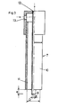
- the Fig. 1 shows a longitudinal section through a backflow lock according to the invention
- the Fig. 2 shows a plan view of the backflow valve
- the Fig. 3 shows a side view partially in section of a nozzle, which serves for supplying the coating material during the laser treatment.
- the non-return valve according to the invention is mounted at the front end of a plasticizing screw 1, which is movable in an injection cylinder.
- the plasticizing screw 1 exerts on the one hand in the plasticizing a rotational movement and on the other hand, an axial movement.
- the non-return valve consists of a directly mounted on the plasticizing screw 1 screw tip 8, a locking sleeve 2 and a locking sleeve 3.
- the locking sleeve 3 is freely movable in a certain range on the screw tip 8.
- All sealing and friction surfaces 4, 5, 6, 14 of the main body of the screw tip 8, the locking sleeve 3 and the locking sleeve 2 have been treated according to the invention by means of a laser beam, wherein the surfaces of the screw tip 8, the locking sleeve 2 and the locking sleeve 3 melted in the processing area were and a supplied or pre-deposited on the friction surfaces 4,5,14 filler a fusion metallurgical connection with the respective base body of the locking sleeve 2, the locking sleeve 3 and the screw tip 8 is received.
- the laser beam was adjusted so that it was at an angle of 30-90 ° to the workpiece surface.
- the parallel to the plane of incidence polarized portion of the laser beam was more than 60%.
- the laser power can be selectively adjusted, for example, by optical instruments, oscillating mirrors, deformable optics, integration optics, the use of multiple laser beams, and flat contact angles.
- This relative movement can be achieved either by a fixed laser beam and a moving workpiece, by a moving laser beam and a stationary workpiece or by a preferably opposite movement of workpiece and laser beam.
- the alloying process can be assisted by heating the screw tip 8, the locking sleeve 2 and / or the locking bushing 3 by other heat sources during the laser treatment or immediately before or after the treatment.
- the main body of the screw tip 8, the locking sleeve 2 and the locking sleeve 3 according to the invention consist of iron-base materials, with melt metallurgical and powder metallurgy steels preferably in the compositions 1.2316 (X36 CrMo 17), 1.2085 (X33 CrS 16), 1.2361 (X91 CrMoV 18), 1.4104 ( X14 CrMoS17), (X4 CrMoS18), 1.4112 (X90 CrMoV 18), 1.4122 (X35 CrMo 17), 1.4528 (X105 CrCoMo 18 2), 1.2379 (X155 CrVMo 12 1), (X39 CrMo 17 1), (X190 CrVMoW 20 4 1) were used.
- the main body of the screw tip 8, the locking sleeve 2 and the lock bushing 3 made of melting or powder metallurgical Kobalbasis- or nickel-based materials or ceramic materials.
- Metals, carbides, nitrides, carbonitrides, borides, sulfides and / or oxides were used singly or in combination as filler metals for the machining of the friction surfaces 4, 5, 14 or the sealing surface 6, preferably Mo, Ti, Cr, Ni, Co, Nb, V, Al, Ta, W, Zr, Hf, Fe, Mn, Ca, B, C, N, Si and the above Links. Furthermore, substances that were sulfur. Contain oxygen, selenium or tellurium, predeposited on the friction surfaces 4, 5 and the sealing surface 6 and / or supplied to these surfaces during the laser treatment.
- Screw tip 8 body made of tempered steel 1.2316.05 (X36 CrMo 17 V); Stop sleeve 3: steel body 1.2379 (X155 Cr V Mo 12 1); Locking sleeve 2 steel body 1.4528 (X105 Cr Co Mo 18 2)
- vanadium carbide was supplied in powder form to the molten bath and this while immersed in inert gas.
- the melting of the body was carried out by means of laser beams, while filler materials were melted in several rings.
- the supply of the filler material took place in the form of powder which was supplied to the friction surfaces 4, 5, 14 and the sealing surface 6 during the laser treatment.
- the filler material can also be supplied in the form of solid wire, flux cored wire, paste or tape or in a combined manner as a powder, solid wire, cored wire, tape or paste and it can also before the laser treatment on the friction surfaces 4, 5, 14 and the sealing surface. 6 be predeposited.
- the melting process is carried out under a predetermined atmosphere by processing the screw tip 8, the stop sleeve 3 or the locking sleeve 2 either in a chamber sealed from the ambient atmosphere, or while these parts are in ambient atmosphere, but of one or more gas jets in selected composition be streamed.
- the in the Fig. 3 shown nozzle 7, which has an inner tube 9 and an outer tube 10.
- the powdery coating material and a gas, preferably argon, are supplied to the friction surfaces 4, 5, 14 or the sealing surface 6 to be processed.
- the space 11 between the inner tube 9 and the outer tube 10 serves to supply a gas jet, which determines the ambient atmosphere for the molten bath.
- a gas jet which determines the ambient atmosphere for the molten bath.
- the surfaces to be coated nitrogen (N 2 ) was supplied through the gap.
- the inner tube 9 protrudes from the outer tube 10.
- the distance e of the front pipe end of the inner tube 9 to the front Pipe end of the outer tube 10 is between -20 mm and +20 mm.
- the diameter of the inner tube 9 is between 2 mm and 6 mm and the diameter D of the outer tube 10 between 8 mm and 30 mm.
Landscapes
- Engineering & Computer Science (AREA)
- Mechanical Engineering (AREA)
- Manufacturing & Machinery (AREA)
- Chemical & Material Sciences (AREA)
- Chemical Kinetics & Catalysis (AREA)
- Materials Engineering (AREA)
- Metallurgy (AREA)
- Organic Chemistry (AREA)
- Injection Moulding Of Plastics Or The Like (AREA)
Claims (29)
- Dispositif de blocage du reflux pour une unité d'injection d'une machine à mouler par injection avec un cylindre de vis comportant une vis préplastificatrice (1) à l'extrémité avant de laquelle est placé le dispositif de blocage du reflux se composant d'une pointe de vis (8), d'une boite de blocage (3) et d'une douille de blocage (2) avec des surfaces correspondantes d'étanchéité et de frottement (4, 5, 6, 14), au moins une partie d'au moins une surface de frottement (4, 5, 14) de la pointe de vis (8), de la boite de blocage (3) et/ou de la douille de blocage (2) étant constituée d'une couche de protection réalisée en une liaison de pyrométallurgie entre le corps de base respectif et un matériau additionnel rapporté ou déposé préalablement, caractérisé en ce qu'au moins le corps de base de la pointe de vis (8) se compose d'un acier au chrome avec au moins une portion de chrome de 12%, et qu'au moins sur les surfaces de frottement (14) de la pointe de vis (8) des matériaux additionnels, tels que des métaux, des carbures, des carbonitrures, des borures, des carboborures, des siliciures, des sulfures et/ou des oxydes, de préférence des composés de Mo, Ti, Cr, Ni, Co, Nb, V, Al, Ta, W, Zr, Hf, Fe, Mn, Ca, Si, B, C et N, sont fondus individuellement ou en combinaison, une zone mixte plus mince que la zone superficielle traitée avec les matériaux additionnels se trouvant entre le corps de base et la zone superficielle traitée avec les matériaux additionnels et les deux zones se composant du matériau du corps de base ainsi que de portions ciblées des matériaux additionnels et en ce que ces deux zones sont composées de cristaux mixtes métalliques et de composés chimiques, de préférence des carbures des types MC1-X, M2C, M6C, M7C3 et de borides des types M2B et M6B, qui contiennent des matériaux du corps de base et/ou des matériaux additionnels, les phases indiquées étant réglées avec des rapports de concentration définis dans la zone superficielle et dans la zone mixte.
- Dispositif de blocage du reflux selon la revendication 1, caractérisé en ce que les corps de base de la pointe de vis (8) et/ou de la boite de blocage (3) et/ou de la douille de blocage (2) se composent de matériaux à base de fer, de préférence dans les composés 1.2316 (X36 CrMo 17), 1.2085 (X33 CrS 16), 1.2361 (X91 CrMoV 18), 1.4104 (X14 CrMoS 17), 1.4105(X4 CrMoS 18), 1.4112 (X90 CrMoV 18), 1.4122 (X35 CrMo 17), 1.4528 (X105 CrCoMo 18 2), 1.2379 (X155 CrVMo 12 1), (X39 CrMo 17 1), (X190 CrVMoW 20 4 1).
- Dispositif de blocage du reflux selon la revendication 1, caractérisé en ce que les corps de base de la pointe de vis (8), de la boite de blocage (3) et/ou de la douille de blocage (2) se composent de matériaux de pyrométallurgie ou de métallurgie des poudres à base de cobalt ou de nickel.
- Dispositif de blocage du reflux selon la revendication 1, caractérisé en ce que les corps de base de la boîte de blocage (3) et/ou de la douille de blocage (2) se composent de matériaux céramiques ou de métaux durs.
- Dispositif de blocage du reflux selon les revendications 1 à 5, caractérisé en ce que des matériaux additionnels, tels que des métaux, des carbures, des carbonitrures, des borures, des carboborures, des siliciures, des sulfures et/ou des oxydes (de préférence les composés susmentionnés de Mo, Ti, Cr, Ni, Co, Nb, V, Al, Ta, W, Zr, Hf, Fe, Mn, Ca, Si, B, C et N) sont fondus individuellement ou en combinaison dans les surfaces de frottement (4, 5, 14) de la boite de blocage (3) et/ou de la douille de blocage (2).
- Dispositif de blocage du reflux selon les revendications 1 à 5, caractérisé en ce que des matériaux additionnels, tels que des métaux, des carbures, des carbonitrures, des borures, des carboborures, des siliciures, des sulfures et/ou des oxydes (de préférence les composés susmentionnés de Mo, Ti, Cr, Ni, Co, Nb, V, Al, Ta, W, Zr, Hf, Fe, Mn, Ca, Si, B, C et N) sont fondus individuellement ou en combinaison dans les surfaces d'étanchéité de la boîte de blocage (3) et/ou de la douille de blocage (2).
- Procédé pour la fabrication d'un dispositif de blocage du reflux selon l'une des revendications 1 à 6, les surfaces de frottement de la pointe de vis (8) et/ou les surfaces de frottement ou les surfaces d'étanchéité de la boîte de blocage (3) et/ou de la douille de blocage (2) recevant des couches superficielles en métal, en métal dur ou en céramique qui sont constituées d'une liaison de pyrométallurgie entre le corps de base respectif et un matériau additionnel rapporté ou déposé préalablement, caractérisé en ce qu'un corps de base en acier avec au moins une portion de chrome de 12%, une résistance à la traction d'au moins 800 N/mm2 et une énergie absorbée au choc d'au moins 50 Joules à 20°C (essai Charpy à entaille en V), est utilisé et en ce que la surface à traiter fait l'objet d'une fusion locale au moyen d'une source d'énergie avec une densité de puissance locale moyenne de plus de 103 watts/cm2 agissant sur le corps de base, la pointe maximale de la température du bain de fusion étant d'au moins 1700 °C et des éléments volumétriques étant, dans les zones du corps de base qui constituent des surfaces de frottement ou d'étanchéité sur la pièce finie, plus courts que 20 sec. en état de fusion et des matériaux additionnels à point de fusion élevé ou des mélanges de matériaux à point de fusion élevé étant, durant cette période, répartis de manière largement homogène dans le bain de fusion, ce qui provoque, lors de la phase suivante de la solidification, la formation d'une couche superficielle avec des matériaux à résistance mécanique élevée finement répartis.
- Procédé selon la revendication 7, caractérisé en ce qu'une ou plusieurs source(s) de rayonnement à haute puissance, de préférence un ou plusieurs laser(s) à haute puissance, est (sont) utilisée(s) comme source d'énergie.
- Procédé selon la revendication 8, caractérisé en ce qu'au moins un rayon laser touche la surface de frottement ou d'étanchéité (4, 5, 6, 14) avec un angle d'incidence de 5°-85°, de préférence entre 55°-85° par rapport à la normale de surface.
- Procédé selon les revendications 8 et 9, caractérisé en ce que la portion du rayon laser polarisé parallèlement au niveau d'incidence est supérieure à 60%.
- Procédé selon l'une des revendications 8 à 10, caractérisé en ce que la répartition dans l'espace et dans le temps de la puissance du rayonnement laser dirigé sur le corps de base peut être réglée de manière ciblée.
- Procédé selon l'une des revendications 7 à 11, caractérisé en ce que, comme corps de base pour la pointe de vis (8), la douille de blocage (2) et/ou la boîte de blocage (3), on utilise des matériaux à base de fer, de préférence dans les composés 1.2316 (X36 CrMo 17), 1.2085 (X33 CrS 16), 1.2361 (X91 CrMoV 18), 1.4104 (X14 CrMoS 17), 1.4105(X4 CrMoS 18), 1.4112 (X90 CrMoV 18), 1.4122 (X35 CrMo 17), 1.4528 (X105 CrCoMo 18 2), 1.2379 (X155 CrVMo 12 1), (X39 CrMo 17 1), (X190 CrVMoW 20 4 1).
- Procédé selon l'une des revendications 7 à 11, caractérisé en ce que, comme corps de base pour la pointe de vis (8), la douille de blocage (2) et/ou la boîte de blocage (3), on utilise des matériaux de pyrométallurgie ou de métallurgie des poudres à base de cobalt ou de nickel.
- Procédé selon l'une des revendications 7 à 11, caractérisé en ce que, comme corps de base pour la douille de blocage (2) et/ou la boîte de blocage (3), on utilise des matériaux céramiques.
- Procédé selon l'une des revendications 7 à 14, caractérisé en ce que, comme matériaux auxiliaires, on utilise individuellement ou en combinaison des métaux, des carbures, des nitrures, des carbonitrures, des borures, des sulfures, des carboborures, des siliciures et des oxydes, de préférence Mo, Ti, Cr, Ni, Co, Nb, V, Al, Ta, w, Zr, Hf, Fe, Mn, Ca, Si, B, C, et N et leurs composés susmentionnés.
- Procédé selon l'une des revendications 7 à 15, caractérisé en ce que des substances contenant du soufre, de l'oxygène, du sélénium et/ou du tellure sont déposées préalablement et/ou rapportées lors du processus de fusion sur les surfaces de frottement ou d'étanchéité (4, 5, 6, 14).
- Procédé selon l'une des revendications 7 à 16, caractérisé en ce que le matériau additionnel est déposé préalablement et/ou rapporté lors du processus de fusion sous forme de poudre, de fil massif, de fil fourré, de pâte ou de bande.
- Procédé selon l'une des revendications 7 à 16, caractérisé en ce que le matériau additionnel est déposé préalablement et/ou rapporté lors du processus de fusion d'une manière combinée sous forme de poudre, de fil massif, de fil fourré, de bande ou de pâte.
- Procédé selon l'une des revendications 7 à 18, caractérisé en ce que, lors du processus de fusion, une atmosphère prédéfinie est mise en place, soit par le fait que la pointe de vis (8), la douille de blocage (2) et/ou la boite de blocage (3) sont traités dans une chambre isolée de l'atmosphère ambiante, soit par le fait que la pointe de vis (8), la douille de blocage (2) et/ou la boîte de blocage (3) sont traités dans l'atmosphère ambiante par un ou plusieurs jets de gaz dans des combinaisons sélectionnées.
- Procédé selon la revendication 19, caractérisé en ce qu'un injecteur double (7) avec un tube intérieur (9) et un tube extérieur (10) est utilisé pour la réalisation d'une atmosphère définie et pour amener le matériau additionnel, le matériau sous forme de poudre et/ou de fil étant guidé à travers le tube intérieur (9) et le tube intérieur (9) ainsi que le tube extérieur (10) étant traversés de gaz de processus identiques ou différents.
- Procédé selon l'une des revendications 7 à 20, caractérisé en ce que, comme gaz de processus, on utilise individuellement ou en combinaisons des gaz nobles, de préférence de l'argon, ou des gaz à action réactive, de préférence de l'azote, auxquels sont rajoutés en outre d'autres gaz en petites quantités, de préférence de l'oxygène.
- Procédé selon l'une des revendications 7 à 18, caractérisé en ce que la fusion des matériaux additionnels dans les surfaces de frottement et/ou d'étanchéité (4, 5, 6, 14) a lieu en une ou en plusieurs trajectoires circulaires et/ou en une ou en plusieurs trajectoires rectilignes ou en courbes spatiales, de préférence en spirales, et/ou par points.
- Procédé selon l'une des revendications 7 à 22, caractérisé en ce qu'après la solidification de la couche superficielle, la pointe de vis (8), la douille de blocage (2) et/ou la boite de blocage (3) sont soumises à un usinage par enlèvement de copeaux.
- Procédé selon la revendication 23, caractérisé en ce que sur la pointe de vis (8) sont pratiqués par un usinage mécanique, de préférence par fraisage, par meulage et/ou par tournage, des évidements latéraux qui constituent les sections de passage pour l'écoulement entre les ailes (16) de la pointe de vis (8).
- Procédé selon l'une des revendications 7 à 23, caractérisé en ce qu'un traitement thermique, de préférence un recuit, de la pointe de vis (8), de la boite de blocage (3) et/ou de la douille de blocage (2) a lieu après le traitement au laser et qu'un trempage et un revenu ou un durcissement par précipitation ont lieu après l'usinage mécanique.
- Procédé selon l'une des revendications 7 à 25, caractérisé en ce que le matériau à base de fer 1.2316.05 (X36 Cr Mo 17 V) est utilisé comme matériau de base pour les pointes de vis (8).
- Procédé selon l'une des revendications 7 à 26, caractérisé en ce que les matériaux à base de fer 1.2379 (X155 CrVMo 12 1), 1.3243 (HS 6-5-2-5) ou (X190 CrVMoW 20 4 1) sont utilisés comme matériaux de base pour la boite de blocage (3).
- Procédé selon l'une des revendications 7 à 27, caractérisé en ce que le matériau à base de fer 1.4528 (X105 Cr Co Mo 18 2) est utilisé comme matériau de base pour la douille de blocage (2).
- Procédé selon l'une des revendications 7 à 28, caractérisé en ce qu'un mélange de poudres se composant de VC, de Ti et de MnS est utilisé comme matériau additionnel.
Applications Claiming Priority (4)
| Application Number | Priority Date | Filing Date | Title |
|---|---|---|---|
| AT163995 | 1995-10-04 | ||
| AT1639/95 | 1995-10-04 | ||
| AT163995 | 1995-10-04 | ||
| PCT/AT1996/000184 WO1997012743A1 (fr) | 1995-10-04 | 1996-10-04 | Dispositif de blocage du reflux pour une unite d'injection d'une machine a mouler par injection |
Publications (3)
| Publication Number | Publication Date |
|---|---|
| EP0853541A1 EP0853541A1 (fr) | 1998-07-22 |
| EP0853541B1 EP0853541B1 (fr) | 2000-04-12 |
| EP0853541B2 true EP0853541B2 (fr) | 2008-04-09 |
Family
ID=3517768
Family Applications (1)
| Application Number | Title | Priority Date | Filing Date |
|---|---|---|---|
| EP96932372A Expired - Lifetime EP0853541B2 (fr) | 1995-10-04 | 1996-10-04 | Dispositif de blocage du reflux pour une unite d'injection d'une machine a mouler par injection |
Country Status (6)
| Country | Link |
|---|---|
| US (1) | US6155816A (fr) |
| EP (1) | EP0853541B2 (fr) |
| AT (1) | ATE191672T1 (fr) |
| CA (1) | CA2230675C (fr) |
| DE (1) | DE59604966D1 (fr) |
| WO (1) | WO1997012743A1 (fr) |
Cited By (1)
| Publication number | Priority date | Publication date | Assignee | Title |
|---|---|---|---|---|
| DE102020111082B4 (de) | 2019-04-25 | 2021-10-14 | Engel Austria Gmbh | Plastifizierschnecke sowie Einspritzaggregat für eine Formgebungsmaschine sowie Formgebungsmaschine |
Families Citing this family (11)
| Publication number | Priority date | Publication date | Assignee | Title |
|---|---|---|---|---|
| JP3549101B2 (ja) * | 2000-06-16 | 2004-08-04 | 日精樹脂工業株式会社 | 逆流防止弁を備えた射出装置 |
| WO2003051604A1 (fr) * | 2001-12-14 | 2003-06-26 | Mannesmann Plastics Machinery Gmbh | Clapet antiretour comportant une couche de protection antiusure et procede de fabrication |
| DE10210464B4 (de) * | 2002-03-09 | 2007-07-26 | Demag Ergotech Gmbh | Rückströmsperre |
| US20070065538A1 (en) * | 2005-09-16 | 2007-03-22 | Husky Injection Molding Systems Ltd. | Molding system having valve including pump |
| US20070254111A1 (en) * | 2006-04-26 | 2007-11-01 | Lineton Warran B | Method for forming a tribologically enhanced surface using laser treating |
| US7425126B2 (en) * | 2006-05-17 | 2008-09-16 | Husky Injection Molding Systems Ltd. | Molding-system valve having knockdown retainer |
| US20110045124A1 (en) * | 2007-09-21 | 2011-02-24 | Mold-Masters (2007) Limited | Injection Molding Nozzle Having A Nozzle Tip With Diamond Crown |
| US20090098234A1 (en) * | 2007-10-11 | 2009-04-16 | Husky Injection Molding Systems Ltd. | Screw with Carbide Inserts |
| CN102232016A (zh) * | 2008-12-10 | 2011-11-02 | 赫斯基注塑系统有限公司 | 改进的止回阀 |
| JP5808648B2 (ja) * | 2010-11-18 | 2015-11-10 | 住友重機械工業株式会社 | スクリューの製造方法およびスクリュー |
| CN102560317B (zh) * | 2010-11-18 | 2014-11-19 | 住友重机械工业株式会社 | 螺杆的制造方法及螺杆 |
Family Cites Families (5)
| Publication number | Priority date | Publication date | Assignee | Title |
|---|---|---|---|---|
| DE3936479A1 (de) * | 1989-11-02 | 1991-05-08 | Guenter Link | Verfahren zur erzeugung von schutzschichten auf materialoberflaechen mittels laserstrahlung |
| DD292159A5 (de) * | 1990-02-27 | 1991-07-25 | Zi Fuer Festkoerperphysik Und Werkstofforschung Der Adw,De | Verfahren zur oberflaechenveredlung von metallischen werkstoffen |
| EP0498286B1 (fr) * | 1991-02-02 | 1995-01-11 | FRIEDRICH THEYSOHN GmbH | Procédé de réalisation d'une couche plus résistante à l'usure |
| US5167971A (en) * | 1991-07-29 | 1992-12-01 | Gill Joseph R | Check valve assembly for injection molding apparatus |
| FR2696759B1 (fr) * | 1992-10-09 | 1994-11-04 | Alsthom Gec | Procédé de nitruration d'une pièce en alliage de titane et dispositif de projection d'azote et de gaz neutre. |
-
1996
- 1996-10-04 CA CA002230675A patent/CA2230675C/fr not_active Expired - Fee Related
- 1996-10-04 US US09/029,555 patent/US6155816A/en not_active Expired - Lifetime
- 1996-10-04 AT AT96932372T patent/ATE191672T1/de not_active IP Right Cessation
- 1996-10-04 EP EP96932372A patent/EP0853541B2/fr not_active Expired - Lifetime
- 1996-10-04 DE DE59604966T patent/DE59604966D1/de not_active Expired - Lifetime
- 1996-10-04 WO PCT/AT1996/000184 patent/WO1997012743A1/fr not_active Ceased
Cited By (1)
| Publication number | Priority date | Publication date | Assignee | Title |
|---|---|---|---|---|
| DE102020111082B4 (de) | 2019-04-25 | 2021-10-14 | Engel Austria Gmbh | Plastifizierschnecke sowie Einspritzaggregat für eine Formgebungsmaschine sowie Formgebungsmaschine |
Also Published As
| Publication number | Publication date |
|---|---|
| US6155816A (en) | 2000-12-05 |
| WO1997012743A1 (fr) | 1997-04-10 |
| CA2230675C (fr) | 2004-02-24 |
| EP0853541A1 (fr) | 1998-07-22 |
| EP0853541B1 (fr) | 2000-04-12 |
| CA2230675A1 (fr) | 1997-04-10 |
| DE59604966D1 (de) | 2000-05-18 |
| ATE191672T1 (de) | 2000-04-15 |
Similar Documents
| Publication | Publication Date | Title |
|---|---|---|
| DE3926627C2 (fr) | ||
| DE3718779C2 (fr) | ||
| DE3937526C2 (de) | Verschleißfeste Titanlegierung, Verfahren zu ihrer Herstellung und ihre Verwendung | |
| EP0853541B2 (fr) | Dispositif de blocage du reflux pour une unite d'injection d'une machine a mouler par injection | |
| DE69721508T2 (de) | Füllen von porosität oder hohlräumen von in einem spritzverfahren hergestellten teilen | |
| DE69333657T2 (de) | Legierung mit hoher Korrosionsbeständigkeit und hoher Verschleissfestigkeit, Verfahren zur Herstellung dieser Erzeugnisse und Ausgangsmaterial für dieses Herstellungsverfahren | |
| DE69802800T2 (de) | Gesintertes mechanisches teil mit abriebfester oberfläche und verfahren zu seiner herstellung | |
| DE102004042492A1 (de) | Verfahren und Vorrichtung zur Herstellung einer Schneid- oder Prägewalze mittels Laserauftragsschweißen | |
| EP0915184B1 (fr) | Procédé de fabrication d'une couche de céramique sur un substrat métallique | |
| DE102005020081A1 (de) | Pulvermetallurgisch hergestellter, verschleißbeständiger Werkstoff | |
| DE60304191T2 (de) | Einspritzdüse für Kraftstoffventil in einem Dieselmotor und Herstellungsverfahren für eine Einspritzdüse | |
| DE3506302C3 (de) | Verfahren zum Oberflächenhärten von Nockenwellen und Vorrichtung zur Durchführung des Verfahrens | |
| EP2948260A1 (fr) | Poudre de projection thermique pour systèmes de coulissement fortement sollicités | |
| DE102004018921A1 (de) | Verfahren zur Herstellung einer Pleuelstange sowie eines Kolbenbolzens | |
| DE19508947A1 (de) | Verschleißfeste, anlaßbeständige und warmfeste Legierung | |
| EP1404484B1 (fr) | Outil de coupe en forme de bande | |
| EP3074167B1 (fr) | Procédés de fabrication d'une matière brute pour un outil d'enlèvement de copeaux | |
| WO2001079575A1 (fr) | Acier allie a l'azote, compacte par pulverisation, procede permettant de le produire et materiau composite produit a partir dudit acier | |
| EP3074166A1 (fr) | Procédé de production d'un produit primaire pour un outil d'usinage par enlèvement de copeaux et produit primaire correspondant | |
| WO2018024763A1 (fr) | Alliage ferreux destiné à la réalisation de couches protectrices anti-usure appliquées par voie thermique | |
| DE3715327C2 (fr) | ||
| EP1857253A1 (fr) | Buse pour machines de moulage par injection et son procédé de fabrication | |
| EP2113578A2 (fr) | Corps en métal doté d'une couche de protection métallique | |
| EP3889292A1 (fr) | Plaque de serrage pour machine à couler sous pression et procédé de fabrication | |
| AT402301B (de) | Schichtkörper mit einer eisen- oder kobaltbasislegierung und verfahren zur herstellung derselben |
Legal Events
| Date | Code | Title | Description |
|---|---|---|---|
| PUAI | Public reference made under article 153(3) epc to a published international application that has entered the european phase |
Free format text: ORIGINAL CODE: 0009012 |
|
| 17P | Request for examination filed |
Effective date: 19980327 |
|
| AK | Designated contracting states |
Kind code of ref document: A1 Designated state(s): AT BE CH DE FR IT LI |
|
| GRAG | Despatch of communication of intention to grant |
Free format text: ORIGINAL CODE: EPIDOS AGRA |
|
| 17Q | First examination report despatched |
Effective date: 19990628 |
|
| GRAG | Despatch of communication of intention to grant |
Free format text: ORIGINAL CODE: EPIDOS AGRA |
|
| GRAH | Despatch of communication of intention to grant a patent |
Free format text: ORIGINAL CODE: EPIDOS IGRA |
|
| GRAH | Despatch of communication of intention to grant a patent |
Free format text: ORIGINAL CODE: EPIDOS IGRA |
|
| GRAA | (expected) grant |
Free format text: ORIGINAL CODE: 0009210 |
|
| AK | Designated contracting states |
Kind code of ref document: B1 Designated state(s): AT BE CH DE FR IT LI |
|
| PG25 | Lapsed in a contracting state [announced via postgrant information from national office to epo] |
Ref country code: FR Free format text: LAPSE BECAUSE OF FAILURE TO SUBMIT A TRANSLATION OF THE DESCRIPTION OR TO PAY THE FEE WITHIN THE PRESCRIBED TIME-LIMIT Effective date: 20000412 |
|
| REF | Corresponds to: |
Ref document number: 191672 Country of ref document: AT Date of ref document: 20000415 Kind code of ref document: T |
|
| REG | Reference to a national code |
Ref country code: CH Ref legal event code: EP |
|
| REF | Corresponds to: |
Ref document number: 59604966 Country of ref document: DE Date of ref document: 20000518 |
|
| ITF | It: translation for a ep patent filed | ||
| EN | Fr: translation not filed | ||
| PG25 | Lapsed in a contracting state [announced via postgrant information from national office to epo] |
Ref country code: LI Free format text: LAPSE BECAUSE OF NON-PAYMENT OF DUE FEES Effective date: 20001031 Ref country code: CH Free format text: LAPSE BECAUSE OF NON-PAYMENT OF DUE FEES Effective date: 20001031 Ref country code: BE Free format text: LAPSE BECAUSE OF NON-PAYMENT OF DUE FEES Effective date: 20001031 |
|
| PLBI | Opposition filed |
Free format text: ORIGINAL CODE: 0009260 |
|
| PLBI | Opposition filed |
Free format text: ORIGINAL CODE: 0009260 |
|
| PLBF | Reply of patent proprietor to notice(s) of opposition |
Free format text: ORIGINAL CODE: EPIDOS OBSO |
|
| 26 | Opposition filed |
Opponent name: BATTENFELD GMBH Effective date: 20001227 |
|
| 26 | Opposition filed |
Opponent name: MANNESMANN PLASTICS MACHINERY AG Effective date: 20010112 Opponent name: BATTENFELD GMBH Effective date: 20001227 |
|
| BERE | Be: lapsed |
Owner name: ENGEL MASCHINENBAU G.M.B.H. Effective date: 20001031 |
|
| REG | Reference to a national code |
Ref country code: CH Ref legal event code: PL |
|
| PLBF | Reply of patent proprietor to notice(s) of opposition |
Free format text: ORIGINAL CODE: EPIDOS OBSO |
|
| PLAB | Opposition data, opponent's data or that of the opponent's representative modified |
Free format text: ORIGINAL CODE: 0009299OPPO |
|
| PLBQ | Unpublished change to opponent data |
Free format text: ORIGINAL CODE: EPIDOS OPPO |
|
| PLBF | Reply of patent proprietor to notice(s) of opposition |
Free format text: ORIGINAL CODE: EPIDOS OBSO |
|
| R26 | Opposition filed (corrected) |
Opponent name: BATTENFELD GMBH * 20010112 MANNESMANN PLASTICS MAC Effective date: 20001227 |
|
| RDAH | Patent revoked |
Free format text: ORIGINAL CODE: EPIDOS REVO |
|
| APAC | Appeal dossier modified |
Free format text: ORIGINAL CODE: EPIDOS NOAPO |
|
| APAC | Appeal dossier modified |
Free format text: ORIGINAL CODE: EPIDOS NOAPO |
|
| APAC | Appeal dossier modified |
Free format text: ORIGINAL CODE: EPIDOS NOAPO |
|
| RAP2 | Party data changed (patent owner data changed or rights of a patent transferred) |
Owner name: ENGEL AUSTRIA GMBH |
|
| APAA | Appeal reference recorded |
Free format text: ORIGINAL CODE: EPIDOS REFN |
|
| PG25 | Lapsed in a contracting state [announced via postgrant information from national office to epo] |
Ref country code: IT Free format text: LAPSE BECAUSE OF NON-PAYMENT OF DUE FEES;WARNING: LAPSES OF ITALIAN PATENTS WITH EFFECTIVE DATE BEFORE 2007 MAY HAVE OCCURRED AT ANY TIME BEFORE 2007. THE CORRECT EFFECTIVE DATE MAY BE DIFFERENT FROM THE ONE RECORDED. Effective date: 20051004 |
|
| APAH | Appeal reference modified |
Free format text: ORIGINAL CODE: EPIDOSCREFNO |
|
| APBU | Appeal procedure closed |
Free format text: ORIGINAL CODE: EPIDOSNNOA9O |
|
| PUAH | Patent maintained in amended form |
Free format text: ORIGINAL CODE: 0009272 |
|
| STAA | Information on the status of an ep patent application or granted ep patent |
Free format text: STATUS: PATENT MAINTAINED AS AMENDED |
|
| 27A | Patent maintained in amended form |
Effective date: 20080409 |
|
| AK | Designated contracting states |
Kind code of ref document: B2 Designated state(s): AT BE CH DE FR IT LI |
|
| PLAB | Opposition data, opponent's data or that of the opponent's representative modified |
Free format text: ORIGINAL CODE: 0009299OPPO |
|
| EN | Fr: translation not filed | ||
| PGFP | Annual fee paid to national office [announced via postgrant information from national office to epo] |
Ref country code: AT Payment date: 20091014 Year of fee payment: 14 |
|
| PG25 | Lapsed in a contracting state [announced via postgrant information from national office to epo] |
Ref country code: AT Free format text: LAPSE BECAUSE OF NON-PAYMENT OF DUE FEES Effective date: 20101004 |
|
| PGFP | Annual fee paid to national office [announced via postgrant information from national office to epo] |
Ref country code: DE Payment date: 20121018 Year of fee payment: 17 |
|
| REG | Reference to a national code |
Ref country code: DE Ref legal event code: R119 Ref document number: 59604966 Country of ref document: DE Effective date: 20140501 |
|
| PG25 | Lapsed in a contracting state [announced via postgrant information from national office to epo] |
Ref country code: DE Free format text: LAPSE BECAUSE OF NON-PAYMENT OF DUE FEES Effective date: 20140501 |