EP2113578A2 - Corps en métal doté d'une couche de protection métallique - Google Patents
Corps en métal doté d'une couche de protection métallique Download PDFInfo
- Publication number
- EP2113578A2 EP2113578A2 EP20090004075 EP09004075A EP2113578A2 EP 2113578 A2 EP2113578 A2 EP 2113578A2 EP 20090004075 EP20090004075 EP 20090004075 EP 09004075 A EP09004075 A EP 09004075A EP 2113578 A2 EP2113578 A2 EP 2113578A2
- Authority
- EP
- European Patent Office
- Prior art keywords
- metal body
- layer
- metal
- protective
- protective layer
- Prior art date
- Legal status (The legal status is an assumption and is not a legal conclusion. Google has not performed a legal analysis and makes no representation as to the accuracy of the status listed.)
- Granted
Links
- 229910052751 metal Inorganic materials 0.000 title claims abstract description 124
- 239000002184 metal Substances 0.000 title claims abstract description 124
- 239000011253 protective coating Substances 0.000 title 1
- 239000011241 protective layer Substances 0.000 claims abstract description 83
- 239000010410 layer Substances 0.000 claims abstract description 53
- 239000012790 adhesive layer Substances 0.000 claims abstract description 24
- 238000000034 method Methods 0.000 claims abstract description 20
- 238000005507 spraying Methods 0.000 claims abstract description 14
- PXHVJJICTQNCMI-UHFFFAOYSA-N nickel Substances [Ni] PXHVJJICTQNCMI-UHFFFAOYSA-N 0.000 claims description 46
- 239000007789 gas Substances 0.000 claims description 26
- 239000000470 constituent Substances 0.000 claims description 24
- XEEYBQQBJWHFJM-UHFFFAOYSA-N iron Substances [Fe] XEEYBQQBJWHFJM-UHFFFAOYSA-N 0.000 claims description 24
- 229910052759 nickel Inorganic materials 0.000 claims description 24
- 239000002245 particle Substances 0.000 claims description 20
- 239000007788 liquid Substances 0.000 claims description 18
- 239000011651 chromium Substances 0.000 claims description 17
- VYZAMTAEIAYCRO-UHFFFAOYSA-N Chromium Chemical compound [Cr] VYZAMTAEIAYCRO-UHFFFAOYSA-N 0.000 claims description 16
- 230000001681 protective effect Effects 0.000 claims description 16
- 229910052804 chromium Inorganic materials 0.000 claims description 15
- 238000003466 welding Methods 0.000 claims description 15
- 229910017052 cobalt Inorganic materials 0.000 claims description 14
- 239000010941 cobalt Substances 0.000 claims description 14
- 229910052742 iron Inorganic materials 0.000 claims description 12
- 239000011593 sulfur Substances 0.000 claims description 11
- 229910052717 sulfur Inorganic materials 0.000 claims description 11
- 229910052799 carbon Inorganic materials 0.000 claims description 10
- 239000011572 manganese Substances 0.000 claims description 10
- 229910052710 silicon Inorganic materials 0.000 claims description 10
- 239000000126 substance Substances 0.000 claims description 10
- NINIDFKCEFEMDL-UHFFFAOYSA-N Sulfur Chemical compound [S] NINIDFKCEFEMDL-UHFFFAOYSA-N 0.000 claims description 9
- 229910052750 molybdenum Inorganic materials 0.000 claims description 9
- 239000011733 molybdenum Substances 0.000 claims description 9
- 239000010703 silicon Substances 0.000 claims description 9
- ZOKXTWBITQBERF-UHFFFAOYSA-N Molybdenum Chemical compound [Mo] ZOKXTWBITQBERF-UHFFFAOYSA-N 0.000 claims description 8
- 229910052748 manganese Inorganic materials 0.000 claims description 8
- PWHULOQIROXLJO-UHFFFAOYSA-N Manganese Chemical compound [Mn] PWHULOQIROXLJO-UHFFFAOYSA-N 0.000 claims description 7
- 238000004056 waste incineration Methods 0.000 claims description 7
- 229910052802 copper Inorganic materials 0.000 claims description 6
- 239000010949 copper Substances 0.000 claims description 6
- 229910052758 niobium Inorganic materials 0.000 claims description 6
- 239000010955 niobium Substances 0.000 claims description 6
- 230000036961 partial effect Effects 0.000 claims description 6
- 229910052698 phosphorus Inorganic materials 0.000 claims description 6
- 239000011574 phosphorus Substances 0.000 claims description 6
- 239000010936 titanium Substances 0.000 claims description 6
- 229910052719 titanium Inorganic materials 0.000 claims description 6
- 230000008569 process Effects 0.000 claims description 5
- 229910052782 aluminium Inorganic materials 0.000 claims description 4
- 238000010438 heat treatment Methods 0.000 claims description 4
- 239000011261 inert gas Substances 0.000 claims description 4
- XAGFODPZIPBFFR-UHFFFAOYSA-N aluminium Chemical compound [Al] XAGFODPZIPBFFR-UHFFFAOYSA-N 0.000 claims description 3
- 238000002156 mixing Methods 0.000 claims description 3
- 238000004064 recycling Methods 0.000 claims description 3
- 239000002023 wood Substances 0.000 claims description 3
- 241001465754 Metazoa Species 0.000 claims description 2
- 239000004568 cement Substances 0.000 claims description 2
- 230000003116 impacting effect Effects 0.000 claims description 2
- 239000012528 membrane Substances 0.000 claims description 2
- 239000012768 molten material Substances 0.000 claims description 2
- 239000010801 sewage sludge Substances 0.000 claims description 2
- 239000000446 fuel Substances 0.000 claims 1
- 238000013021 overheating Methods 0.000 claims 1
- 239000003380 propellant Substances 0.000 claims 1
- 239000000463 material Substances 0.000 description 25
- 229910045601 alloy Inorganic materials 0.000 description 23
- 239000000956 alloy Substances 0.000 description 23
- GUTLYIVDDKVIGB-UHFFFAOYSA-N cobalt atom Chemical compound [Co] GUTLYIVDDKVIGB-UHFFFAOYSA-N 0.000 description 11
- 238000002844 melting Methods 0.000 description 11
- 230000008018 melting Effects 0.000 description 11
- 230000015572 biosynthetic process Effects 0.000 description 9
- 235000019589 hardness Nutrition 0.000 description 8
- 239000000203 mixture Substances 0.000 description 8
- XUIMIQQOPSSXEZ-UHFFFAOYSA-N Silicon Chemical compound [Si] XUIMIQQOPSSXEZ-UHFFFAOYSA-N 0.000 description 7
- 239000003570 air Substances 0.000 description 7
- 150000002739 metals Chemical class 0.000 description 7
- XKRFYHLGVUSROY-UHFFFAOYSA-N Argon Chemical compound [Ar] XKRFYHLGVUSROY-UHFFFAOYSA-N 0.000 description 6
- IJGRMHOSHXDMSA-UHFFFAOYSA-N Atomic nitrogen Chemical compound N#N IJGRMHOSHXDMSA-UHFFFAOYSA-N 0.000 description 6
- OKTJSMMVPCPJKN-UHFFFAOYSA-N Carbon Chemical compound [C] OKTJSMMVPCPJKN-UHFFFAOYSA-N 0.000 description 6
- 230000007797 corrosion Effects 0.000 description 5
- 238000005260 corrosion Methods 0.000 description 5
- 239000007921 spray Substances 0.000 description 5
- 230000035882 stress Effects 0.000 description 5
- 238000005299 abrasion Methods 0.000 description 4
- 150000001805 chlorine compounds Chemical class 0.000 description 4
- 230000000694 effects Effects 0.000 description 4
- 230000006872 improvement Effects 0.000 description 4
- 239000011344 liquid material Substances 0.000 description 4
- 239000002923 metal particle Substances 0.000 description 4
- 239000000843 powder Substances 0.000 description 4
- RYGMFSIKBFXOCR-UHFFFAOYSA-N Copper Chemical compound [Cu] RYGMFSIKBFXOCR-UHFFFAOYSA-N 0.000 description 3
- 241001295925 Gegenes Species 0.000 description 3
- OAICVXFJPJFONN-UHFFFAOYSA-N Phosphorus Chemical compound [P] OAICVXFJPJFONN-UHFFFAOYSA-N 0.000 description 3
- 229910000831 Steel Inorganic materials 0.000 description 3
- RTAQQCXQSZGOHL-UHFFFAOYSA-N Titanium Chemical compound [Ti] RTAQQCXQSZGOHL-UHFFFAOYSA-N 0.000 description 3
- 229910052786 argon Inorganic materials 0.000 description 3
- 238000000576 coating method Methods 0.000 description 3
- 229910001092 metal group alloy Inorganic materials 0.000 description 3
- GUCVJGMIXFAOAE-UHFFFAOYSA-N niobium atom Chemical compound [Nb] GUCVJGMIXFAOAE-UHFFFAOYSA-N 0.000 description 3
- 229910052757 nitrogen Inorganic materials 0.000 description 3
- 239000001301 oxygen Substances 0.000 description 3
- 229910052760 oxygen Inorganic materials 0.000 description 3
- 238000007493 shaping process Methods 0.000 description 3
- 239000007787 solid Substances 0.000 description 3
- 238000007711 solidification Methods 0.000 description 3
- 230000008023 solidification Effects 0.000 description 3
- 239000010959 steel Substances 0.000 description 3
- 229910000851 Alloy steel Inorganic materials 0.000 description 2
- VEXZGXHMUGYJMC-UHFFFAOYSA-M Chloride anion Chemical compound [Cl-] VEXZGXHMUGYJMC-UHFFFAOYSA-M 0.000 description 2
- ZAMOUSCENKQFHK-UHFFFAOYSA-N Chlorine atom Chemical compound [Cl] ZAMOUSCENKQFHK-UHFFFAOYSA-N 0.000 description 2
- UCKMPCXJQFINFW-UHFFFAOYSA-N Sulphide Chemical compound [S-2] UCKMPCXJQFINFW-UHFFFAOYSA-N 0.000 description 2
- 230000001070 adhesive effect Effects 0.000 description 2
- 239000012080 ambient air Substances 0.000 description 2
- 230000008901 benefit Effects 0.000 description 2
- 238000006243 chemical reaction Methods 0.000 description 2
- 239000000460 chlorine Substances 0.000 description 2
- 229910052801 chlorine Inorganic materials 0.000 description 2
- 239000003245 coal Substances 0.000 description 2
- 239000011248 coating agent Substances 0.000 description 2
- 238000002485 combustion reaction Methods 0.000 description 2
- 230000000295 complement effect Effects 0.000 description 2
- 150000001875 compounds Chemical class 0.000 description 2
- 238000001816 cooling Methods 0.000 description 2
- 238000010285 flame spraying Methods 0.000 description 2
- 239000003546 flue gas Substances 0.000 description 2
- 239000006199 nebulizer Substances 0.000 description 2
- 150000004763 sulfides Chemical class 0.000 description 2
- 229910000838 Al alloy Inorganic materials 0.000 description 1
- UGFAIRIUMAVXCW-UHFFFAOYSA-N Carbon monoxide Chemical compound [O+]#[C-] UGFAIRIUMAVXCW-UHFFFAOYSA-N 0.000 description 1
- 239000002253 acid Substances 0.000 description 1
- 150000007513 acids Chemical class 0.000 description 1
- 230000009471 action Effects 0.000 description 1
- 230000006978 adaptation Effects 0.000 description 1
- 239000000853 adhesive Substances 0.000 description 1
- QVGXLLKOCUKJST-UHFFFAOYSA-N atomic oxygen Chemical compound [O] QVGXLLKOCUKJST-UHFFFAOYSA-N 0.000 description 1
- 239000011324 bead Substances 0.000 description 1
- 150000001721 carbon Chemical class 0.000 description 1
- 239000000567 combustion gas Substances 0.000 description 1
- 239000002131 composite material Substances 0.000 description 1
- 238000005336 cracking Methods 0.000 description 1
- 230000006378 damage Effects 0.000 description 1
- 230000003247 decreasing effect Effects 0.000 description 1
- 230000001419 dependent effect Effects 0.000 description 1
- 238000009826 distribution Methods 0.000 description 1
- 238000005516 engineering process Methods 0.000 description 1
- 230000007613 environmental effect Effects 0.000 description 1
- -1 ferrous metals Chemical class 0.000 description 1
- 230000004927 fusion Effects 0.000 description 1
- 238000000227 grinding Methods 0.000 description 1
- 230000012447 hatching Effects 0.000 description 1
- 230000017525 heat dissipation Effects 0.000 description 1
- 229910001385 heavy metal Inorganic materials 0.000 description 1
- 239000001307 helium Substances 0.000 description 1
- 229910052734 helium Inorganic materials 0.000 description 1
- SWQJXJOGLNCZEY-UHFFFAOYSA-N helium atom Chemical compound [He] SWQJXJOGLNCZEY-UHFFFAOYSA-N 0.000 description 1
- 238000000265 homogenisation Methods 0.000 description 1
- 230000008595 infiltration Effects 0.000 description 1
- 238000001764 infiltration Methods 0.000 description 1
- 239000004615 ingredient Substances 0.000 description 1
- 238000003780 insertion Methods 0.000 description 1
- 230000037431 insertion Effects 0.000 description 1
- 238000005304 joining Methods 0.000 description 1
- 229910001338 liquidmetal Inorganic materials 0.000 description 1
- 238000003754 machining Methods 0.000 description 1
- WPBNNNQJVZRUHP-UHFFFAOYSA-L manganese(2+);methyl n-[[2-(methoxycarbonylcarbamothioylamino)phenyl]carbamothioyl]carbamate;n-[2-(sulfidocarbothioylamino)ethyl]carbamodithioate Chemical compound [Mn+2].[S-]C(=S)NCCNC([S-])=S.COC(=O)NC(=S)NC1=CC=CC=C1NC(=S)NC(=O)OC WPBNNNQJVZRUHP-UHFFFAOYSA-L 0.000 description 1
- 239000000155 melt Substances 0.000 description 1
- 230000003647 oxidation Effects 0.000 description 1
- 238000007254 oxidation reaction Methods 0.000 description 1
- 235000011837 pasties Nutrition 0.000 description 1
- 239000004033 plastic Substances 0.000 description 1
- 229920003023 plastic Polymers 0.000 description 1
- 230000000750 progressive effect Effects 0.000 description 1
- 230000002829 reductive effect Effects 0.000 description 1
- 230000000717 retained effect Effects 0.000 description 1
- 238000005488 sandblasting Methods 0.000 description 1
- 230000003746 surface roughness Effects 0.000 description 1
- 230000008646 thermal stress Effects 0.000 description 1
Images
Classifications
-
- B—PERFORMING OPERATIONS; TRANSPORTING
- B23—MACHINE TOOLS; METAL-WORKING NOT OTHERWISE PROVIDED FOR
- B23K—SOLDERING OR UNSOLDERING; WELDING; CLADDING OR PLATING BY SOLDERING OR WELDING; CUTTING BY APPLYING HEAT LOCALLY, e.g. FLAME CUTTING; WORKING BY LASER BEAM
- B23K9/00—Arc welding or cutting
- B23K9/04—Welding for other purposes than joining, e.g. built-up welding
-
- B—PERFORMING OPERATIONS; TRANSPORTING
- B32—LAYERED PRODUCTS
- B32B—LAYERED PRODUCTS, i.e. PRODUCTS BUILT-UP OF STRATA OF FLAT OR NON-FLAT, e.g. CELLULAR OR HONEYCOMB, FORM
- B32B15/00—Layered products comprising a layer of metal
- B32B15/01—Layered products comprising a layer of metal all layers being exclusively metallic
-
- C—CHEMISTRY; METALLURGY
- C22—METALLURGY; FERROUS OR NON-FERROUS ALLOYS; TREATMENT OF ALLOYS OR NON-FERROUS METALS
- C22C—ALLOYS
- C22C19/00—Alloys based on nickel or cobalt
- C22C19/007—Alloys based on nickel or cobalt with a light metal (alkali metal Li, Na, K, Rb, Cs; earth alkali metal Be, Mg, Ca, Sr, Ba, Al Ga, Ge, Ti) or B, Si, Zr, Hf, Sc, Y, lanthanides, actinides, as the next major constituent
-
- C—CHEMISTRY; METALLURGY
- C22—METALLURGY; FERROUS OR NON-FERROUS ALLOYS; TREATMENT OF ALLOYS OR NON-FERROUS METALS
- C22C—ALLOYS
- C22C19/00—Alloys based on nickel or cobalt
- C22C19/03—Alloys based on nickel or cobalt based on nickel
-
- C—CHEMISTRY; METALLURGY
- C22—METALLURGY; FERROUS OR NON-FERROUS ALLOYS; TREATMENT OF ALLOYS OR NON-FERROUS METALS
- C22C—ALLOYS
- C22C19/00—Alloys based on nickel or cobalt
- C22C19/03—Alloys based on nickel or cobalt based on nickel
- C22C19/05—Alloys based on nickel or cobalt based on nickel with chromium
- C22C19/058—Alloys based on nickel or cobalt based on nickel with chromium without Mo and W
-
- C—CHEMISTRY; METALLURGY
- C22—METALLURGY; FERROUS OR NON-FERROUS ALLOYS; TREATMENT OF ALLOYS OR NON-FERROUS METALS
- C22C—ALLOYS
- C22C19/00—Alloys based on nickel or cobalt
- C22C19/07—Alloys based on nickel or cobalt based on cobalt
-
- C—CHEMISTRY; METALLURGY
- C22—METALLURGY; FERROUS OR NON-FERROUS ALLOYS; TREATMENT OF ALLOYS OR NON-FERROUS METALS
- C22C—ALLOYS
- C22C30/00—Alloys containing less than 50% by weight of each constituent
-
- C—CHEMISTRY; METALLURGY
- C23—COATING METALLIC MATERIAL; COATING MATERIAL WITH METALLIC MATERIAL; CHEMICAL SURFACE TREATMENT; DIFFUSION TREATMENT OF METALLIC MATERIAL; COATING BY VACUUM EVAPORATION, BY SPUTTERING, BY ION IMPLANTATION OR BY CHEMICAL VAPOUR DEPOSITION, IN GENERAL; INHIBITING CORROSION OF METALLIC MATERIAL OR INCRUSTATION IN GENERAL
- C23C—COATING METALLIC MATERIAL; COATING MATERIAL WITH METALLIC MATERIAL; SURFACE TREATMENT OF METALLIC MATERIAL BY DIFFUSION INTO THE SURFACE, BY CHEMICAL CONVERSION OR SUBSTITUTION; COATING BY VACUUM EVAPORATION, BY SPUTTERING, BY ION IMPLANTATION OR BY CHEMICAL VAPOUR DEPOSITION, IN GENERAL
- C23C24/00—Coating starting from inorganic powder
- C23C24/02—Coating starting from inorganic powder by application of pressure only
- C23C24/04—Impact or kinetic deposition of particles
-
- C—CHEMISTRY; METALLURGY
- C23—COATING METALLIC MATERIAL; COATING MATERIAL WITH METALLIC MATERIAL; CHEMICAL SURFACE TREATMENT; DIFFUSION TREATMENT OF METALLIC MATERIAL; COATING BY VACUUM EVAPORATION, BY SPUTTERING, BY ION IMPLANTATION OR BY CHEMICAL VAPOUR DEPOSITION, IN GENERAL; INHIBITING CORROSION OF METALLIC MATERIAL OR INCRUSTATION IN GENERAL
- C23C—COATING METALLIC MATERIAL; COATING MATERIAL WITH METALLIC MATERIAL; SURFACE TREATMENT OF METALLIC MATERIAL BY DIFFUSION INTO THE SURFACE, BY CHEMICAL CONVERSION OR SUBSTITUTION; COATING BY VACUUM EVAPORATION, BY SPUTTERING, BY ION IMPLANTATION OR BY CHEMICAL VAPOUR DEPOSITION, IN GENERAL
- C23C24/00—Coating starting from inorganic powder
- C23C24/08—Coating starting from inorganic powder by application of heat or pressure and heat
-
- C—CHEMISTRY; METALLURGY
- C23—COATING METALLIC MATERIAL; COATING MATERIAL WITH METALLIC MATERIAL; CHEMICAL SURFACE TREATMENT; DIFFUSION TREATMENT OF METALLIC MATERIAL; COATING BY VACUUM EVAPORATION, BY SPUTTERING, BY ION IMPLANTATION OR BY CHEMICAL VAPOUR DEPOSITION, IN GENERAL; INHIBITING CORROSION OF METALLIC MATERIAL OR INCRUSTATION IN GENERAL
- C23C—COATING METALLIC MATERIAL; COATING MATERIAL WITH METALLIC MATERIAL; SURFACE TREATMENT OF METALLIC MATERIAL BY DIFFUSION INTO THE SURFACE, BY CHEMICAL CONVERSION OR SUBSTITUTION; COATING BY VACUUM EVAPORATION, BY SPUTTERING, BY ION IMPLANTATION OR BY CHEMICAL VAPOUR DEPOSITION, IN GENERAL
- C23C28/00—Coating for obtaining at least two superposed coatings either by methods not provided for in a single one of groups C23C2/00 - C23C26/00 or by combinations of methods provided for in subclasses C23C and C25C or C25D
- C23C28/02—Coating for obtaining at least two superposed coatings either by methods not provided for in a single one of groups C23C2/00 - C23C26/00 or by combinations of methods provided for in subclasses C23C and C25C or C25D only coatings only including layers of metallic material
- C23C28/021—Coating for obtaining at least two superposed coatings either by methods not provided for in a single one of groups C23C2/00 - C23C26/00 or by combinations of methods provided for in subclasses C23C and C25C or C25D only coatings only including layers of metallic material including at least one metal alloy layer
-
- C—CHEMISTRY; METALLURGY
- C23—COATING METALLIC MATERIAL; COATING MATERIAL WITH METALLIC MATERIAL; CHEMICAL SURFACE TREATMENT; DIFFUSION TREATMENT OF METALLIC MATERIAL; COATING BY VACUUM EVAPORATION, BY SPUTTERING, BY ION IMPLANTATION OR BY CHEMICAL VAPOUR DEPOSITION, IN GENERAL; INHIBITING CORROSION OF METALLIC MATERIAL OR INCRUSTATION IN GENERAL
- C23C—COATING METALLIC MATERIAL; COATING MATERIAL WITH METALLIC MATERIAL; SURFACE TREATMENT OF METALLIC MATERIAL BY DIFFUSION INTO THE SURFACE, BY CHEMICAL CONVERSION OR SUBSTITUTION; COATING BY VACUUM EVAPORATION, BY SPUTTERING, BY ION IMPLANTATION OR BY CHEMICAL VAPOUR DEPOSITION, IN GENERAL
- C23C28/00—Coating for obtaining at least two superposed coatings either by methods not provided for in a single one of groups C23C2/00 - C23C26/00 or by combinations of methods provided for in subclasses C23C and C25C or C25D
- C23C28/02—Coating for obtaining at least two superposed coatings either by methods not provided for in a single one of groups C23C2/00 - C23C26/00 or by combinations of methods provided for in subclasses C23C and C25C or C25D only coatings only including layers of metallic material
- C23C28/023—Coating for obtaining at least two superposed coatings either by methods not provided for in a single one of groups C23C2/00 - C23C26/00 or by combinations of methods provided for in subclasses C23C and C25C or C25D only coatings only including layers of metallic material only coatings of metal elements only
-
- C—CHEMISTRY; METALLURGY
- C23—COATING METALLIC MATERIAL; COATING MATERIAL WITH METALLIC MATERIAL; CHEMICAL SURFACE TREATMENT; DIFFUSION TREATMENT OF METALLIC MATERIAL; COATING BY VACUUM EVAPORATION, BY SPUTTERING, BY ION IMPLANTATION OR BY CHEMICAL VAPOUR DEPOSITION, IN GENERAL; INHIBITING CORROSION OF METALLIC MATERIAL OR INCRUSTATION IN GENERAL
- C23C—COATING METALLIC MATERIAL; COATING MATERIAL WITH METALLIC MATERIAL; SURFACE TREATMENT OF METALLIC MATERIAL BY DIFFUSION INTO THE SURFACE, BY CHEMICAL CONVERSION OR SUBSTITUTION; COATING BY VACUUM EVAPORATION, BY SPUTTERING, BY ION IMPLANTATION OR BY CHEMICAL VAPOUR DEPOSITION, IN GENERAL
- C23C4/00—Coating by spraying the coating material in the molten state, e.g. by flame, plasma or electric discharge
- C23C4/12—Coating by spraying the coating material in the molten state, e.g. by flame, plasma or electric discharge characterised by the method of spraying
- C23C4/123—Spraying molten metal
-
- C—CHEMISTRY; METALLURGY
- C23—COATING METALLIC MATERIAL; COATING MATERIAL WITH METALLIC MATERIAL; CHEMICAL SURFACE TREATMENT; DIFFUSION TREATMENT OF METALLIC MATERIAL; COATING BY VACUUM EVAPORATION, BY SPUTTERING, BY ION IMPLANTATION OR BY CHEMICAL VAPOUR DEPOSITION, IN GENERAL; INHIBITING CORROSION OF METALLIC MATERIAL OR INCRUSTATION IN GENERAL
- C23C—COATING METALLIC MATERIAL; COATING MATERIAL WITH METALLIC MATERIAL; SURFACE TREATMENT OF METALLIC MATERIAL BY DIFFUSION INTO THE SURFACE, BY CHEMICAL CONVERSION OR SUBSTITUTION; COATING BY VACUUM EVAPORATION, BY SPUTTERING, BY ION IMPLANTATION OR BY CHEMICAL VAPOUR DEPOSITION, IN GENERAL
- C23C4/00—Coating by spraying the coating material in the molten state, e.g. by flame, plasma or electric discharge
- C23C4/12—Coating by spraying the coating material in the molten state, e.g. by flame, plasma or electric discharge characterised by the method of spraying
- C23C4/131—Wire arc spraying
-
- Y—GENERAL TAGGING OF NEW TECHNOLOGICAL DEVELOPMENTS; GENERAL TAGGING OF CROSS-SECTIONAL TECHNOLOGIES SPANNING OVER SEVERAL SECTIONS OF THE IPC; TECHNICAL SUBJECTS COVERED BY FORMER USPC CROSS-REFERENCE ART COLLECTIONS [XRACs] AND DIGESTS
- Y02—TECHNOLOGIES OR APPLICATIONS FOR MITIGATION OR ADAPTATION AGAINST CLIMATE CHANGE
- Y02T—CLIMATE CHANGE MITIGATION TECHNOLOGIES RELATED TO TRANSPORTATION
- Y02T50/00—Aeronautics or air transport
- Y02T50/60—Efficient propulsion technologies, e.g. for aircraft
Definitions
- the invention relates to a metal body, on which at least partially a metal layer is applied as a thermal and / or mechanical and / or chemical protection, which consists of at least three sub-layers, of which the first as an adhesive layer rests directly on the surface of the metal body and thereon at least two further protective layers are constructed.
- At least one protective layer contains the constituents iron and carbon and silicon and manganese and chromium and molybdenum and nickel and cobalt.
- An alloy with the components carbon, silicon, manganese, chromium, molybdenum, nickel and iron is from the DE 10 2004 047 known and has proven itself in a combined load of heat, various gases and mechanical stress.
- This alloy differs from the protective layer according to the invention by the missing constituent cobalt.
- this known alloy has been shown that it is very resistant to high temperatures and against several acids and also has a good abrasion resistance, but always only as long as the protective layer is still as a whole complete layer.
- elemental cobalt is its melting temperature of 1495 ° C, which is lower than several other elemental constituents of the alloy of the present invention. Only manganese at 1244 ° C has an even lower melting temperature. Silicon at 1410 ° C and nickel at 1455 ° C have about the same melting temperature as cobalt. Pure iron melts only at 1535 ° C, pure chromium at 1857 ° C, pure molybdenum at 2623 ° C and pure carbon at 3550 ° C. As already mentioned, compounds have different melting temperatures, depending on the proportion of the constituents contained therein.
- liquid cobalt can still flow into the crater around the point of impact together with the other, still liquid constituents and thereby form a full surface connection on an enlarged surface produce.
- Waste incineration with a share of various plastics, coated materials and composite materials produces various chlorides that are resistant to nickel, which is why a high proportion of nickel optimizes the protective layer for use in waste incineration plants.
- the flue gases contain both sulfur and chlorides.
- a protective layer adapted to it contains the largest proportions of chromium and nickel. It is also conceivable that a first protective layer has a large proportion of chromium and a second protective layer has a large proportion of nickel. The effects of both protective layers add up.
- Niobium improves the flowability and thus the weldability of the liquid melt.
- Titanium increases the high corrosion resistance and the strength of the protective layer.
- a particularly interesting embodiment of the protective layer composition according to the invention contains the constituents within the following limits: iron of 5 to 20%, carbon of 0.2 to 3.5%, silicon of 0.2 to 2.5%, manganese of 0, 05 to 5.0%, phosphorus of 0.01 to 0.1%, sulfur of 0.001 to 0.2%, chromium of 21 to 29%, molybdenum of 1 to 8.5%, nickel of 4 to 12.5 %, Cobalt from 43 to 54%, copper from 0.011 to 0.1%, niobium from 1 to 7.2% and titanium from 0.004 to 1%. If the proportion of a component is changed, then it must be checked whether then the Shares of other ingredients are still within the limits. Otherwise, their share must be adjusted accordingly. If, as a result, the correspondingly decreased levels of other constituents would undesirably alter the characteristics of the alloy for a particular application, the proportion of properties relevant to the properties must also be adjusted to the intended application.
- An alloy that has been successfully used in many of the applications mentioned here contains the following proportions: iron 13.84%, carbon 0.233%, silicon 0.63%, manganese 0.98%, phosphorus 0.016%, sulfur 0.005%, chromium 25.6%, molybdenum 0.94%, nickel 7.08%, cobalt 48.5%, copper 0.011%, niobium 2.17% and titanium 0.004%.
- optimizing the protective layer with an increase in the protective properties against a mixture of different environmental properties - in this case the combination of high temperatures, high mechanical loads and chemically aggressive gases - by no means includes an improvement in the adhesion to the metal body to be coated. Rather, due to the different properties of temperature-dependent expansion, elasticity and hardness, it is to be feared that the adhesiveness will deteriorate if the protective properties are improved. However, since the protective layer suddenly becomes completely ineffective in a chipping, the adhesive strength is one of the essential properties.
- the invention describes two different embodiments for the formation of an adhesive layer.
- the first alternative is the insertion of another metal alloy whose components are chosen are that they primarily withstand high shear and tensile forces exerted on the protective layer. Equally important is the thermal resistance, since the protective layer with its high thermal conductivity almost completely forwards thermal energy. In contrast, the adhesive layer is exposed to mechanical and chemical stress only to a very limited extent, because they are intercepted by the protective layer.
- a second alternative for the formation of the adhesive layer is the mechanical interlocking between the metal body and the protective layer. Similar to the example of serration between a gear and its shaft, the surface is unevenly shaped, ideally even with undercuts, with the surfaces of the protective layer and the metal body formed complementary to each other.
- the adhesive layer thus differs from the adjacent layers not by a different material composition but by a different material shaping.
- an adhesive layer of other material between the metal body and the protective layer different materials are suitable depending on the application and composition of the metal body.
- Good results were obtained with nickel, aluminum and chromium for the protective layer according to the invention.
- alloys of about 20% aluminum and about 80% nickel or about 20% chromium and 80% nickel have shown a very good adhesion when applying the protective layer according to the invention.
- the adhesive layer according to the invention is dimensioned according to micrometers.
- the impact velocity of the particles of the later protective layer is of much greater influence than would have been expected according to the general state of knowledge of the coating technology.
- the elements first move within the liquid layer held together by cohesive forces on the surface, so that they do not immediately fall off the surface, but mix well with one another within the liquid layer. Some elements move within the liquid layer so fast that they leave their boundaries again and thereby enlarge the wetted area again.
- a further increase in the impact speed does not lead to an even better mixing or expansion of the color areas but to a rebound of the color elements.
- a method according to the invention for applying metal particles of the inventive alloy in liquid or pasty consistency as a protective layer on metal bodies that their speed when impacting the surface of the metal body is so high that some particles from the struck area of the surface of the metal body dissolve out and move these particles slightly.
- the particles dissolved out leave depressions in the surface, which are filled with the liquid material of the protective layer.
- the effective interface between the layers increases, so that the specific size of forces acting on the interface is reduced and thus the adhesion is further improved.
- the recesses may even form undercuts with respect to the surface behind which the liquid material of the protective layer b.z.w. the adhesive layer flows and forms a claw-like attachment after solidification.
- the dissolved particles of the metal body are flowed around by the liquid alloy of the applied layer and thereby held. If the temperature of the liquid alloy is significantly higher than the melting temperature of the metal body to be coated, the dissolved metal particles are at least fused or completely liquefied and thereby integrated into the new layer.
- a speed of 50 m / sec or 180 km / h corresponds to the maximum speed of some automobiles, which are known to be extremely deformed upon impact with this speed on a fixed obstacle.
- a further increase in speed from 50 to 300 m / sec is already close to the speed of sound, which is 331 to 349 m / sec in air, depending on their temperature.
- Such particle velocities are e.g. when sandblasting reached and exceeded. The comparison makes it clear that at speeds of this magnitude very many depressions are struck in the surface of the body to be coated.
- the method according to the invention is suitable for various principles of metal spraying.
- flame spraying with wire or rod of the spray material is supplied in the form of a wire or a rod and continuously melted in the center of an acetylene-oxygen flame.
- a nebulizer gas eg compressed air or nitrogen
- the droplet-shaped spray particles are removed from the melting area and thrown onto the surface to be coated.
- the spray material is prepared as a powder and in an acetylene-oxygen flame on or melted and hurled using the expanding combustion gases on the prepared workpiece surface.
- an additional gas such as argon or nitrogen can also be used to accelerate the powder particles.
- arc spraying two wires formed from the constituents of the protective layer are respectively connected to one pole of a power source, melted in an arc, and sputtered by means of atomizing gas, e.g. Compressed air, thrown on the prepared workpiece surface.
- atomizing gas e.g. Compressed air
- the arc spraying is possible by the electrical conductivity of the metallic components.
- Egg principle disadvantage of liquid metal is the high propensity to form oxides with the ambient air.
- nitrogen or argon as nebulizer gas largely prevents oxidation of the materials.
- a principal advantage of metal spraying is that even relatively thin-walled hollow bodies such as heat exchangers can be coated well, since the material to be coated is only slightly heated and therefore neither significantly deforms nor tends to form cracks in the cooling phase.
- welding is understood to mean, in accordance with DIN ISO 857-1, the non-detachable joining of components using heat.
- the fusion welding is suitable, so a localized melt flow without the application of additional external forces.
- DIN 8580 describes the coating of a workpiece by welding as build-up welding.
- the invention alternatively proposes the following method:
- a wire is pushed out continuously, which contains all components of the respective sub-layer.
- the wire and the metal body are connected to the two poles of a welding power source.
- An arc is formed between the wire and the metal body which liquefies the components at the tip of the wire and spills it within the arc onto the metal body.
- Around the arc flows from an annular nozzle opening a protective gas, which forms a frustoconical protective jacket against the atmosphere.
- the special feature of the method according to the invention is that the flow velocity of the protective gas is significantly higher than that required for the formation of the protective jacket and the protective gas additionally accelerates the components of the wire moved by the arc, so that they penetrate into the molten outer layer of the metal body penetrate and partially mix with this layer.
- the adhesive layer consists of a partial mixing of the molten material from the wire and the molten, uppermost layer of the metal body, thereby causing mechanical interlocking between the metal body and the protective layer.
- the adhesive layer is therefore not characterized by its material, but by their shape.
- the protective gas may be an inert gas whose constituents are kept away from the molten layers of the metal body and the molten constituents of the wire.
- This welding principle is called MIG welding, ie welding with a metal inert gas. Examples of such inert inert gases are argon or helium.
- MIG welding ie welding with a metal inert gas. Examples of such inert inert gases are argon or helium.
- the MIG process is special makes sense if the metal body to be coated consists of a high-alloy steel, non-ferrous metals or Al alloys.
- the metal body to be coated is made of unalloyed or low alloy steel
- the MAG process offers advantages.
- MAG stands for "metal-active gas", with CO 2 being used as the active gas, which ensures better heat dissipation and easily enriches the weld metal with carbon. In line with the task, this carbon content increases the adhesion of the layers to each other.
- the alloys according to the invention are usually still machinable and / or can be processed by grinding directly after application.
- the protective layer has been heated only once over a certain temperature limit, the hardness increases significantly, depending on the relative proportion of the constituents, but a certain degree of elasticity is retained.
- heating in the temperature ranges up to 150 °, up to 300 °, up to 500 °, up to 1000 ° and up to 1500 ° C have proven useful.
- metal bodies coated in accordance with the invention are particularly suitable for applications in which high mechanical strength at high ambient temperatures and chemical stress are important.
- the invention mentions evaporator pipes, finned wall pipes, membrane walls, superheating pipes, bulkheads, shredders, shredder pipes, grinders, screw conveyors, grapples, gate valves, grates and other functions in wood heating, animal recycling plants, crematoria, shredder plants, cement mills, waste incineration plants with sewage sludge admixture, other waste incineration plants, Recycling plants, coal-fired power plants, other power plants, pharmaceutical plants, cracking plants and other petrochemical plants
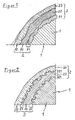
- FIG. 1 In FIG. 1 is to be seen from a section through the surface of a metal body 1, a small part on which two protective layers 22 have been sprayed. The representation is greatly enlarged, since the protective layers 22 in practice usually have a thickness of a few 100 micrometers. Between the surface of the metal body 1 and the first protective layer 22, an adhesive layer 21 is applied from a different material. In this case, a different composition is characterized in the drawing by different hatching.
- FIG. 1 Due to the polygonal shape of the dividing lines between the different layers, it can be seen that many small particles have broken out of the coated surface. It is easy to understand that the notches on the impact of the applied at high speed Particles have emerged. It can be seen that this increases the surface area compared to the original state, which improves the adhesion.
- FIG. 2 is the same section of a cross section through a metal body 1 as in FIG. 1 shown on the two protective layers 22 are also applied.
- FIG. 2 clearly another, wavy formation of the dividing lines between the individual layers recognizable. The shape is similar to the waves that a liquid strikes when a solid dips into it. This comparison also corresponds approximately to the process that leads to the formation of wavy lines:
- FIG. 2 is very nicely illustrated that thereby the effective surface is greatly increased and a number of undercuts formed perpendicular to the layers, which provide for a toothing of the layers together, resulting in a significant improvement in the adhesion.
- this formation is limited to a certain zone, which thereby assumes the function of the adhesive layer 21 - and surpasses their effect compared to spraying.
- This zone is in FIG. 2 each marked by braces.
- FIG. 1 it is plausibilized that the formation of the holding layer 21 penetrates deeper into the metal body 1 than when spraying. Therefore, the welding of the protective layers 22 is primarily suitable for thick-walled or solid metal body 1.
Landscapes
- Chemical & Material Sciences (AREA)
- Engineering & Computer Science (AREA)
- Mechanical Engineering (AREA)
- Materials Engineering (AREA)
- Metallurgy (AREA)
- Organic Chemistry (AREA)
- Chemical Kinetics & Catalysis (AREA)
- Physics & Mathematics (AREA)
- Plasma & Fusion (AREA)
- Coating By Spraying Or Casting (AREA)
- Laminated Bodies (AREA)
- Other Surface Treatments For Metallic Materials (AREA)
Applications Claiming Priority (1)
| Application Number | Priority Date | Filing Date | Title |
|---|---|---|---|
| DE102008018539A DE102008018539A1 (de) | 2008-04-12 | 2008-04-12 | Metallkörper mit metallischer Schutzschicht |
Publications (3)
| Publication Number | Publication Date |
|---|---|
| EP2113578A2 true EP2113578A2 (fr) | 2009-11-04 |
| EP2113578A3 EP2113578A3 (fr) | 2010-02-24 |
| EP2113578B1 EP2113578B1 (fr) | 2017-11-08 |
Family
ID=40821780
Family Applications (1)
| Application Number | Title | Priority Date | Filing Date |
|---|---|---|---|
| EP09004075.9A Not-in-force EP2113578B1 (fr) | 2008-04-12 | 2009-03-21 | Corps en métal doté d'une couche de protection métallique |
Country Status (2)
| Country | Link |
|---|---|
| EP (1) | EP2113578B1 (fr) |
| DE (1) | DE102008018539A1 (fr) |
Cited By (1)
| Publication number | Priority date | Publication date | Assignee | Title |
|---|---|---|---|---|
| WO2012055398A1 (fr) * | 2010-10-28 | 2012-05-03 | Eads Deutschland Gmbh | Procédés de modification ciblée de matières au cours du processus sélectif de fusion par laser |
Families Citing this family (3)
| Publication number | Priority date | Publication date | Assignee | Title |
|---|---|---|---|---|
| JP5606994B2 (ja) * | 2010-09-30 | 2014-10-15 | 株式会社神戸製鋼所 | 肉盛溶接材料及び肉盛溶接金属が溶接された機械部品 |
| CN106710767B (zh) * | 2016-12-09 | 2018-08-17 | 宁波大榭开发区银鑫磁业有限公司 | 一种耐腐蚀多镀层钕铁硼及制备工艺 |
| DE102016124588A1 (de) * | 2016-12-16 | 2018-06-21 | Vdm Metals International Gmbh | Verwendung einer nickel-chrom-molybdän-legierung |
Citations (1)
| Publication number | Priority date | Publication date | Assignee | Title |
|---|---|---|---|---|
| DE102004047196A1 (de) | 2004-09-29 | 2006-04-06 | Berthold, Jürgen | Verfahren zur Herstellung einer mehrlagigen Schutzschicht auf einem Metallgegenstand durch Metallspritzen |
Family Cites Families (18)
| Publication number | Priority date | Publication date | Assignee | Title |
|---|---|---|---|---|
| US3274371A (en) * | 1965-06-01 | 1966-09-20 | Union Carbide Corp | Method of depositing metal |
| DE2334470C3 (de) * | 1973-07-06 | 1983-01-27 | AGA AB, 18181 Lidingö | Vorrichtung zum Lichtbogen-Auftragsschweißen mit zwei Elektroden |
| DE4447514C2 (de) * | 1994-01-14 | 1996-07-25 | Castolin Sa | Verfahren zur Herstellung eines Hilfsmittels zum thermischen Spritzen und seine Verwendung als Pulverfüllung von Fülldraht |
| DE4411296C2 (de) * | 1994-01-14 | 1995-12-21 | Castolin Sa | Zwei- oder mehrphasige korrosionsfeste Beschichtung, Verfahren zu ihrer Herstellung und Verwendung von Beschichtungswerkstoff |
| JPH07316772A (ja) * | 1994-05-27 | 1995-12-05 | Mitsubishi Materials Corp | 溶射用Ni基合金粉末およびNi基合金溶射層 |
| JPH08296023A (ja) * | 1995-04-26 | 1996-11-12 | Nittetsu Hard Kk | 被覆用材料およびこの材料が被覆された金属浴浸漬用部材 |
| US6001426A (en) * | 1996-07-25 | 1999-12-14 | Utron Inc. | High velocity pulsed wire-arc spray |
| JP2991991B2 (ja) * | 1997-03-24 | 1999-12-20 | トーカロ株式会社 | 耐高温環境用溶射被覆部材およびその製造方法 |
| JP2991990B2 (ja) * | 1997-03-24 | 1999-12-20 | トーカロ株式会社 | 耐高温環境用溶射被覆部材およびその製造方法 |
| DE19721818A1 (de) * | 1997-05-26 | 1998-12-10 | Schreck Mieves Gmbh | Verschleißfestes Weichenteil und Verfahren zur Herstellung eines verschleißfesten Weichenteils |
| JP3934251B2 (ja) * | 1997-06-10 | 2007-06-20 | 株式会社東芝 | Tig溶接方法および装置 |
| DE19733306C1 (de) * | 1997-08-01 | 1999-05-06 | Juergen Dr Ing Roethig | Zusatzmaterial zum thermischen Beschichten tribologisch beanspruchter Bauteile |
| DE19942857C2 (de) * | 1999-09-08 | 2001-07-05 | Sulzer Metco Ag Wohlen | Durch Plasmaspritzen erzeugte dicke Schichten auf Aluminiumoxid-Basis |
| ATE383455T1 (de) * | 2000-11-07 | 2008-01-15 | Sulzer Metco Osu Gmbh | Verfahren zur herstellung von verschleiss- und/oder korrosionsfesten oberflächenbeschichtungen sowie mittel zur durchführung desselben |
| DE10308563B3 (de) * | 2003-02-27 | 2004-08-19 | Federal-Mogul Burscheid Gmbh | Zylinderlaufbuchse mit Verschleißschutzbeschichtung, ihre Herstellung und ihre Verwendung |
| JP4000075B2 (ja) * | 2003-02-27 | 2007-10-31 | 株式会社東芝 | ロータの補修方法 |
| DE102004060538B3 (de) * | 2004-12-16 | 2006-03-16 | Daimlerchrysler Ag | Verfahren zur Bildung von Hartmetallschichten und Zylinderkopf für Brennkraftmaschinen mit Ventilsitzringen aus Hartmetall |
| DE102005053531A1 (de) * | 2005-11-08 | 2007-05-10 | Man Turbo Ag | Wärmedämmende Schutzschicht für ein Bauteil innerhalb des Heißgasbereiches einer Gasturbine |
-
2008
- 2008-04-12 DE DE102008018539A patent/DE102008018539A1/de not_active Withdrawn
-
2009
- 2009-03-21 EP EP09004075.9A patent/EP2113578B1/fr not_active Not-in-force
Patent Citations (1)
| Publication number | Priority date | Publication date | Assignee | Title |
|---|---|---|---|---|
| DE102004047196A1 (de) | 2004-09-29 | 2006-04-06 | Berthold, Jürgen | Verfahren zur Herstellung einer mehrlagigen Schutzschicht auf einem Metallgegenstand durch Metallspritzen |
Cited By (2)
| Publication number | Priority date | Publication date | Assignee | Title |
|---|---|---|---|---|
| WO2012055398A1 (fr) * | 2010-10-28 | 2012-05-03 | Eads Deutschland Gmbh | Procédés de modification ciblée de matières au cours du processus sélectif de fusion par laser |
| EP3659738A1 (fr) * | 2010-10-28 | 2020-06-03 | Airbus Defence and Space GmbH | Procédé de changement ciblé de matériau lors du procédé sélective de fusion laser |
Also Published As
| Publication number | Publication date |
|---|---|
| DE102008018539A1 (de) | 2009-10-15 |
| EP2113578B1 (fr) | 2017-11-08 |
| EP2113578A3 (fr) | 2010-02-24 |
Similar Documents
| Publication | Publication Date | Title |
|---|---|---|
| DE602004005150T2 (de) | Verfahren zum hybriden Lichtbogen-Laserschweissen ferritischer Stähle | |
| EP0776985B1 (fr) | Procédé de disposition d'une couche métallique d'adhérence pour des couches isolantes sur articles métalliques | |
| EP0740591B1 (fr) | Revetement biphase ou polyphase | |
| EP1041173B1 (fr) | Bloc-cylindres en métal léger, méthode pour sa fabrication et dispositif pour la mise en oeuvre de cette méthode | |
| DE4411296C2 (de) | Zwei- oder mehrphasige korrosionsfeste Beschichtung, Verfahren zu ihrer Herstellung und Verwendung von Beschichtungswerkstoff | |
| WO2014114715A1 (fr) | Poudre de projection thermique pour systèmes de coulissement fortement sollicités | |
| EP3325685B1 (fr) | Procédé pour recouvrir une surface de glissement de cylindre d'un bloc-cylindres, bloc-cylindres avec une surface de glissement de cylindre recouverte et moteur | |
| WO2020221689A1 (fr) | Procédé de fabrication d'un composant en acier et composant en acier | |
| EP2113578B1 (fr) | Corps en métal doté d'une couche de protection métallique | |
| EP0972606B1 (fr) | Matériau pulvérulent pour des couches résistantes à l'usure et procédé d'application de celles-ci | |
| EP3314033B1 (fr) | Alliage ferreux destiné à la réalisation de couches protectrices anti-usure appliquées par voie thermique | |
| EP0853541B2 (fr) | Dispositif de blocage du reflux pour une unite d'injection d'une machine a mouler par injection | |
| DE102009049875A1 (de) | Bremsscheibe mit einem ringförmigen Reibkörper und Verfahren zum Herstellen des Reibkörpers | |
| WO2022167042A1 (fr) | Utilisation d'un alliage nickel-chrome-fer-molybdène sans titane | |
| DE2356640B2 (de) | Seelenelektrode | |
| DE102013100580A1 (de) | Verfahren zum Herstellen eines als metallischer Verbundwerkstoff ausgeführten Flachprodukts, Stahlflachprodukt und Verwendung eines Stahlflachprodukts | |
| DE102019209650B4 (de) | Verfahren zur Ausbildung einer Schmelzschweißverbindung an Bauteilen aus einem Stahl | |
| DE2161453B2 (de) | Verfahren zur Herstellung eines Reibbelages auf Unterlagen, wie Bremsen oder Kupplungen mittels Plasmastrahl | |
| DD160344A5 (de) | Verfahren zur oberflaechenhaertung eines auf eisen basierenden legierungssubstrats | |
| EP2816135A1 (fr) | Procédé d'injection de poudre à plasma pour le revêtement de panneaux pour parois de chaudière en liaison avec un appareil à faisceau laser | |
| EP3733340A1 (fr) | Outil de coulée pour coulée sous pression de métal | |
| WO2023098932A1 (fr) | Matériau d'apport pour projection thermique, et procédé de production | |
| WO2024170615A1 (fr) | Matériau composite à carbure intégré | |
| DE29918960U1 (de) | Pulverförmiger Zusatzwerkstoff | |
| DE2364175A1 (de) | Austenitischer manganstahl mit niob und/oder tantalkarbiden zum auftragschweissen auf gegenstaende aus stahl |
Legal Events
| Date | Code | Title | Description |
|---|---|---|---|
| PUAI | Public reference made under article 153(3) epc to a published international application that has entered the european phase |
Free format text: ORIGINAL CODE: 0009012 |
|
| AK | Designated contracting states |
Kind code of ref document: A2 Designated state(s): AT BE BG CH CY CZ DE DK EE ES FI FR GB GR HR HU IE IS IT LI LT LU LV MC MK MT NL NO PL PT RO SE SI SK TR |
|
| AX | Request for extension of the european patent |
Extension state: AL BA RS |
|
| PUAL | Search report despatched |
Free format text: ORIGINAL CODE: 0009013 |
|
| AK | Designated contracting states |
Kind code of ref document: A3 Designated state(s): AT BE BG CH CY CZ DE DK EE ES FI FR GB GR HR HU IE IS IT LI LT LU LV MC MK MT NL NO PL PT RO SE SI SK TR |
|
| AX | Request for extension of the european patent |
Extension state: AL BA RS |
|
| 17P | Request for examination filed |
Effective date: 20100731 |
|
| 17Q | First examination report despatched |
Effective date: 20100830 |
|
| AKX | Designation fees paid |
Designated state(s): AT BE BG CH CY CZ DE DK EE ES FI FR GB GR HR HU IE IS IT LI LT LU LV MC MK MT NL NO PL PT RO SE SI SK TR |
|
| RIC1 | Information provided on ipc code assigned before grant |
Ipc: C23C 24/10 20060101ALI20150429BHEP Ipc: C22C 19/03 20060101ALI20150429BHEP Ipc: B23K 9/04 20060101ALI20150429BHEP Ipc: C23C 28/02 20060101ALI20150429BHEP Ipc: C22C 19/00 20060101ALI20150429BHEP Ipc: C22C 19/05 20060101ALI20150429BHEP Ipc: B32B 15/01 20060101ALI20150429BHEP Ipc: C22C 19/07 20060101AFI20150429BHEP Ipc: C22C 30/00 20060101ALI20150429BHEP Ipc: C23C 18/02 20060101ALI20150429BHEP Ipc: C23C 24/04 20060101ALI20150429BHEP Ipc: C23C 4/12 20060101ALI20150429BHEP |
|
| GRAP | Despatch of communication of intention to grant a patent |
Free format text: ORIGINAL CODE: EPIDOSNIGR1 |
|
| INTG | Intention to grant announced |
Effective date: 20160420 |
|
| RAP1 | Party data changed (applicant data changed or rights of an application transferred) |
Owner name: BERTHOLD, JUERGEN |
|
| RIN1 | Information on inventor provided before grant (corrected) |
Inventor name: BERTHOLD, JUERGEN |
|
| GRAJ | Information related to disapproval of communication of intention to grant by the applicant or resumption of examination proceedings by the epo deleted |
Free format text: ORIGINAL CODE: EPIDOSDIGR1 |
|
| INTC | Intention to grant announced (deleted) | ||
| GRAP | Despatch of communication of intention to grant a patent |
Free format text: ORIGINAL CODE: EPIDOSNIGR1 |
|
| INTG | Intention to grant announced |
Effective date: 20161206 |
|
| GRAS | Grant fee paid |
Free format text: ORIGINAL CODE: EPIDOSNIGR3 |
|
| GRAA | (expected) grant |
Free format text: ORIGINAL CODE: 0009210 |
|
| RAP1 | Party data changed (applicant data changed or rights of an application transferred) |
Owner name: BERTHOLD, JUERGEN |
|
| RIN1 | Information on inventor provided before grant (corrected) |
Inventor name: BERTHOLD, JUERGEN |
|
| AK | Designated contracting states |
Kind code of ref document: B1 Designated state(s): AT BE BG CH CY CZ DE DK EE ES FI FR GB GR HR HU IE IS IT LI LT LU LV MC MK MT NL NO PL PT RO SE SI SK TR |
|
| REG | Reference to a national code |
Ref country code: GB Ref legal event code: FG4D Free format text: NOT ENGLISH |
|
| REG | Reference to a national code |
Ref country code: CH Ref legal event code: EP Ref country code: AT Ref legal event code: REF Ref document number: 944220 Country of ref document: AT Kind code of ref document: T Effective date: 20171115 |
|
| REG | Reference to a national code |
Ref country code: IE Ref legal event code: FG4D Free format text: LANGUAGE OF EP DOCUMENT: GERMAN |
|
| REG | Reference to a national code |
Ref country code: DE Ref legal event code: R096 Ref document number: 502009014512 Country of ref document: DE |
|
| REG | Reference to a national code |
Ref country code: NL Ref legal event code: MP Effective date: 20171108 |
|
| REG | Reference to a national code |
Ref country code: LT Ref legal event code: MG4D |
|
| PG25 | Lapsed in a contracting state [announced via postgrant information from national office to epo] |
Ref country code: NO Free format text: LAPSE BECAUSE OF FAILURE TO SUBMIT A TRANSLATION OF THE DESCRIPTION OR TO PAY THE FEE WITHIN THE PRESCRIBED TIME-LIMIT Effective date: 20180208 Ref country code: NL Free format text: LAPSE BECAUSE OF FAILURE TO SUBMIT A TRANSLATION OF THE DESCRIPTION OR TO PAY THE FEE WITHIN THE PRESCRIBED TIME-LIMIT Effective date: 20171108 Ref country code: LT Free format text: LAPSE BECAUSE OF FAILURE TO SUBMIT A TRANSLATION OF THE DESCRIPTION OR TO PAY THE FEE WITHIN THE PRESCRIBED TIME-LIMIT Effective date: 20171108 Ref country code: FI Free format text: LAPSE BECAUSE OF FAILURE TO SUBMIT A TRANSLATION OF THE DESCRIPTION OR TO PAY THE FEE WITHIN THE PRESCRIBED TIME-LIMIT Effective date: 20171108 Ref country code: SE Free format text: LAPSE BECAUSE OF FAILURE TO SUBMIT A TRANSLATION OF THE DESCRIPTION OR TO PAY THE FEE WITHIN THE PRESCRIBED TIME-LIMIT Effective date: 20171108 Ref country code: ES Free format text: LAPSE BECAUSE OF FAILURE TO SUBMIT A TRANSLATION OF THE DESCRIPTION OR TO PAY THE FEE WITHIN THE PRESCRIBED TIME-LIMIT Effective date: 20171108 |
|
| PG25 | Lapsed in a contracting state [announced via postgrant information from national office to epo] |
Ref country code: LV Free format text: LAPSE BECAUSE OF FAILURE TO SUBMIT A TRANSLATION OF THE DESCRIPTION OR TO PAY THE FEE WITHIN THE PRESCRIBED TIME-LIMIT Effective date: 20171108 Ref country code: BG Free format text: LAPSE BECAUSE OF FAILURE TO SUBMIT A TRANSLATION OF THE DESCRIPTION OR TO PAY THE FEE WITHIN THE PRESCRIBED TIME-LIMIT Effective date: 20180208 Ref country code: IS Free format text: LAPSE BECAUSE OF FAILURE TO SUBMIT A TRANSLATION OF THE DESCRIPTION OR TO PAY THE FEE WITHIN THE PRESCRIBED TIME-LIMIT Effective date: 20180308 Ref country code: HR Free format text: LAPSE BECAUSE OF FAILURE TO SUBMIT A TRANSLATION OF THE DESCRIPTION OR TO PAY THE FEE WITHIN THE PRESCRIBED TIME-LIMIT Effective date: 20171108 Ref country code: GR Free format text: LAPSE BECAUSE OF FAILURE TO SUBMIT A TRANSLATION OF THE DESCRIPTION OR TO PAY THE FEE WITHIN THE PRESCRIBED TIME-LIMIT Effective date: 20180209 |
|
| PG25 | Lapsed in a contracting state [announced via postgrant information from national office to epo] |
Ref country code: CZ Free format text: LAPSE BECAUSE OF FAILURE TO SUBMIT A TRANSLATION OF THE DESCRIPTION OR TO PAY THE FEE WITHIN THE PRESCRIBED TIME-LIMIT Effective date: 20171108 Ref country code: EE Free format text: LAPSE BECAUSE OF FAILURE TO SUBMIT A TRANSLATION OF THE DESCRIPTION OR TO PAY THE FEE WITHIN THE PRESCRIBED TIME-LIMIT Effective date: 20171108 Ref country code: CY Free format text: LAPSE BECAUSE OF FAILURE TO SUBMIT A TRANSLATION OF THE DESCRIPTION OR TO PAY THE FEE WITHIN THE PRESCRIBED TIME-LIMIT Effective date: 20171108 Ref country code: SK Free format text: LAPSE BECAUSE OF FAILURE TO SUBMIT A TRANSLATION OF THE DESCRIPTION OR TO PAY THE FEE WITHIN THE PRESCRIBED TIME-LIMIT Effective date: 20171108 Ref country code: DK Free format text: LAPSE BECAUSE OF FAILURE TO SUBMIT A TRANSLATION OF THE DESCRIPTION OR TO PAY THE FEE WITHIN THE PRESCRIBED TIME-LIMIT Effective date: 20171108 |
|
| REG | Reference to a national code |
Ref country code: DE Ref legal event code: R097 Ref document number: 502009014512 Country of ref document: DE |
|
| PG25 | Lapsed in a contracting state [announced via postgrant information from national office to epo] |
Ref country code: RO Free format text: LAPSE BECAUSE OF FAILURE TO SUBMIT A TRANSLATION OF THE DESCRIPTION OR TO PAY THE FEE WITHIN THE PRESCRIBED TIME-LIMIT Effective date: 20171108 Ref country code: IT Free format text: LAPSE BECAUSE OF FAILURE TO SUBMIT A TRANSLATION OF THE DESCRIPTION OR TO PAY THE FEE WITHIN THE PRESCRIBED TIME-LIMIT Effective date: 20171108 Ref country code: PL Free format text: LAPSE BECAUSE OF FAILURE TO SUBMIT A TRANSLATION OF THE DESCRIPTION OR TO PAY THE FEE WITHIN THE PRESCRIBED TIME-LIMIT Effective date: 20171108 |
|
| PLBE | No opposition filed within time limit |
Free format text: ORIGINAL CODE: 0009261 |
|
| STAA | Information on the status of an ep patent application or granted ep patent |
Free format text: STATUS: NO OPPOSITION FILED WITHIN TIME LIMIT |
|
| PG25 | Lapsed in a contracting state [announced via postgrant information from national office to epo] |
Ref country code: MT Free format text: LAPSE BECAUSE OF FAILURE TO SUBMIT A TRANSLATION OF THE DESCRIPTION OR TO PAY THE FEE WITHIN THE PRESCRIBED TIME-LIMIT Effective date: 20171108 |
|
| REG | Reference to a national code |
Ref country code: DE Ref legal event code: R119 Ref document number: 502009014512 Country of ref document: DE |
|
| 26N | No opposition filed |
Effective date: 20180809 |
|
| REG | Reference to a national code |
Ref country code: CH Ref legal event code: PL |
|
| GBPC | Gb: european patent ceased through non-payment of renewal fee |
Effective date: 20180321 |
|
| PG25 | Lapsed in a contracting state [announced via postgrant information from national office to epo] |
Ref country code: SI Free format text: LAPSE BECAUSE OF FAILURE TO SUBMIT A TRANSLATION OF THE DESCRIPTION OR TO PAY THE FEE WITHIN THE PRESCRIBED TIME-LIMIT Effective date: 20171108 Ref country code: MC Free format text: LAPSE BECAUSE OF FAILURE TO SUBMIT A TRANSLATION OF THE DESCRIPTION OR TO PAY THE FEE WITHIN THE PRESCRIBED TIME-LIMIT Effective date: 20171108 |
|
| REG | Reference to a national code |
Ref country code: BE Ref legal event code: MM Effective date: 20180331 |
|
| REG | Reference to a national code |
Ref country code: IE Ref legal event code: MM4A |
|
| PG25 | Lapsed in a contracting state [announced via postgrant information from national office to epo] |
Ref country code: LU Free format text: LAPSE BECAUSE OF NON-PAYMENT OF DUE FEES Effective date: 20180321 |
|
| PG25 | Lapsed in a contracting state [announced via postgrant information from national office to epo] |
Ref country code: IE Free format text: LAPSE BECAUSE OF NON-PAYMENT OF DUE FEES Effective date: 20180321 Ref country code: DE Free format text: LAPSE BECAUSE OF NON-PAYMENT OF DUE FEES Effective date: 20181002 |
|
| PG25 | Lapsed in a contracting state [announced via postgrant information from national office to epo] |
Ref country code: BE Free format text: LAPSE BECAUSE OF NON-PAYMENT OF DUE FEES Effective date: 20180331 Ref country code: GB Free format text: LAPSE BECAUSE OF NON-PAYMENT OF DUE FEES Effective date: 20180321 Ref country code: CH Free format text: LAPSE BECAUSE OF NON-PAYMENT OF DUE FEES Effective date: 20180331 Ref country code: LI Free format text: LAPSE BECAUSE OF NON-PAYMENT OF DUE FEES Effective date: 20180331 |
|
| PG25 | Lapsed in a contracting state [announced via postgrant information from national office to epo] |
Ref country code: FR Free format text: LAPSE BECAUSE OF NON-PAYMENT OF DUE FEES Effective date: 20180331 |
|
| REG | Reference to a national code |
Ref country code: AT Ref legal event code: MM01 Ref document number: 944220 Country of ref document: AT Kind code of ref document: T Effective date: 20180321 |
|
| PG25 | Lapsed in a contracting state [announced via postgrant information from national office to epo] |
Ref country code: AT Free format text: LAPSE BECAUSE OF NON-PAYMENT OF DUE FEES Effective date: 20180321 |
|
| PG25 | Lapsed in a contracting state [announced via postgrant information from national office to epo] |
Ref country code: TR Free format text: LAPSE BECAUSE OF FAILURE TO SUBMIT A TRANSLATION OF THE DESCRIPTION OR TO PAY THE FEE WITHIN THE PRESCRIBED TIME-LIMIT Effective date: 20171108 |
|
| PG25 | Lapsed in a contracting state [announced via postgrant information from national office to epo] |
Ref country code: PT Free format text: LAPSE BECAUSE OF FAILURE TO SUBMIT A TRANSLATION OF THE DESCRIPTION OR TO PAY THE FEE WITHIN THE PRESCRIBED TIME-LIMIT Effective date: 20171108 Ref country code: HU Free format text: LAPSE BECAUSE OF FAILURE TO SUBMIT A TRANSLATION OF THE DESCRIPTION OR TO PAY THE FEE WITHIN THE PRESCRIBED TIME-LIMIT; INVALID AB INITIO Effective date: 20090321 |
|
| PG25 | Lapsed in a contracting state [announced via postgrant information from national office to epo] |
Ref country code: MK Free format text: LAPSE BECAUSE OF NON-PAYMENT OF DUE FEES Effective date: 20171108 |