EP0854260B1 - Ver-/Entriegelungsvorrichtung mit preiswertem Betätiger - Google Patents
Ver-/Entriegelungsvorrichtung mit preiswertem Betätiger Download PDFInfo
- Publication number
- EP0854260B1 EP0854260B1 EP19970403023 EP97403023A EP0854260B1 EP 0854260 B1 EP0854260 B1 EP 0854260B1 EP 19970403023 EP19970403023 EP 19970403023 EP 97403023 A EP97403023 A EP 97403023A EP 0854260 B1 EP0854260 B1 EP 0854260B1
- Authority
- EP
- European Patent Office
- Prior art keywords
- latch
- tongue
- fact
- locking device
- locking
- Prior art date
- Legal status (The legal status is an assumption and is not a legal conclusion. Google has not performed a legal analysis and makes no representation as to the accuracy of the status listed.)
- Expired - Lifetime
Links
Images
Classifications
-
- E—FIXED CONSTRUCTIONS
- E05—LOCKS; KEYS; WINDOW OR DOOR FITTINGS; SAFES
- E05B—LOCKS; ACCESSORIES THEREFOR; HANDCUFFS
- E05B47/00—Operating or controlling locks or other fastening devices by electric or magnetic means
- E05B47/02—Movement of the bolt by electromagnetic means; Adaptation of locks, latches, or parts thereof, for movement of the bolt by electromagnetic means
- E05B47/023—Movement of the bolt by electromagnetic means; Adaptation of locks, latches, or parts thereof, for movement of the bolt by electromagnetic means the bolt moving pivotally or rotatively
-
- E—FIXED CONSTRUCTIONS
- E05—LOCKS; KEYS; WINDOW OR DOOR FITTINGS; SAFES
- E05B—LOCKS; ACCESSORIES THEREFOR; HANDCUFFS
- E05B15/00—Other details of locks; Parts for engagement by bolts of fastening devices
- E05B15/0053—Other details of locks; Parts for engagement by bolts of fastening devices means providing a stable, i.e. indexed, position of lock parts
-
- E—FIXED CONSTRUCTIONS
- E05—LOCKS; KEYS; WINDOW OR DOOR FITTINGS; SAFES
- E05B—LOCKS; ACCESSORIES THEREFOR; HANDCUFFS
- E05B47/00—Operating or controlling locks or other fastening devices by electric or magnetic means
- E05B47/0001—Operating or controlling locks or other fastening devices by electric or magnetic means with electric actuators; Constructional features thereof
- E05B47/0012—Operating or controlling locks or other fastening devices by electric or magnetic means with electric actuators; Constructional features thereof with rotary electromotors
-
- E—FIXED CONSTRUCTIONS
- E05—LOCKS; KEYS; WINDOW OR DOOR FITTINGS; SAFES
- E05B—LOCKS; ACCESSORIES THEREFOR; HANDCUFFS
- E05B47/00—Operating or controlling locks or other fastening devices by electric or magnetic means
- E05B47/0001—Operating or controlling locks or other fastening devices by electric or magnetic means with electric actuators; Constructional features thereof
- E05B2047/0014—Constructional features of actuators or power transmissions therefor
- E05B2047/0015—Output elements of actuators
- E05B2047/0017—Output elements of actuators with rotary motion
-
- E—FIXED CONSTRUCTIONS
- E05—LOCKS; KEYS; WINDOW OR DOOR FITTINGS; SAFES
- E05B—LOCKS; ACCESSORIES THEREFOR; HANDCUFFS
- E05B47/00—Operating or controlling locks or other fastening devices by electric or magnetic means
- E05B47/0001—Operating or controlling locks or other fastening devices by electric or magnetic means with electric actuators; Constructional features thereof
- E05B2047/0014—Constructional features of actuators or power transmissions therefor
- E05B2047/0018—Details of actuator transmissions
- E05B2047/0026—Clutches, couplings or braking arrangements
- E05B2047/0031—Clutches, couplings or braking arrangements of the elastic type
-
- E—FIXED CONSTRUCTIONS
- E05—LOCKS; KEYS; WINDOW OR DOOR FITTINGS; SAFES
- E05B—LOCKS; ACCESSORIES THEREFOR; HANDCUFFS
- E05B47/00—Operating or controlling locks or other fastening devices by electric or magnetic means
- E05B47/0001—Operating or controlling locks or other fastening devices by electric or magnetic means with electric actuators; Constructional features thereof
- E05B47/0002—Operating or controlling locks or other fastening devices by electric or magnetic means with electric actuators; Constructional features thereof with electromagnets
- E05B47/0003—Operating or controlling locks or other fastening devices by electric or magnetic means with electric actuators; Constructional features thereof with electromagnets having a movable core
- E05B47/0005—Operating or controlling locks or other fastening devices by electric or magnetic means with electric actuators; Constructional features thereof with electromagnets having a movable core said core being rotary movable
-
- E—FIXED CONSTRUCTIONS
- E05—LOCKS; KEYS; WINDOW OR DOOR FITTINGS; SAFES
- E05C—BOLTS OR FASTENING DEVICES FOR WINGS, SPECIALLY FOR DOORS OR WINDOWS
- E05C3/00—Fastening devices with bolts moving pivotally or rotatively
- E05C3/02—Fastening devices with bolts moving pivotally or rotatively without latching action
- E05C3/04—Fastening devices with bolts moving pivotally or rotatively without latching action with operating handle or equivalent member rigid with the bolt
- E05C3/041—Fastening devices with bolts moving pivotally or rotatively without latching action with operating handle or equivalent member rigid with the bolt rotating about an axis perpendicular to the surface on which the fastener is mounted
Definitions
- the present invention relates to a device for locking and, more specifically, a device for maintaining closed position of an opening flap.
- a interesting application consists in particular in ensuring the blocking of a locking / unlocking control, i.e. ensuring mechanical blocking preventing the use of the normal means of locking / unlocking of any opening flap.
- Such a lock / unlock control can, for example, prevent the movement of a flap opening or mechanically blocking the movement of the control member of said opening flap.
- such a device locking / unlocking could be implemented to condemn the opening of the fuel flap or the glove box or to cooperate, in a side door lock, with the function child conviction or the super-conviction function.
- the locking device / unlocking will simply be used to position a latch so as to prevent the opening of the opening flap which does not require low power since the movement of the latch is carried out without whether there is to overcome any significant resistance or to drive a mechanism, only the inertia of the latch opposing the movement.
- the invention therefore provides a device for locking device comprising an actuator using a motor electric, characterized in that said electric motor is of low power and carries on its output shaft a latch, which it rotates between two positions called locking and unlocking, positioning means ensuring the maintenance of the latch in each of said two positions.
- the locking device according to the invention is also remarkable in that the positioning means can be consist of an elastic tongue secured to the latch and a finger fixed, or vice versa, with a fixed elastic tongue and a finger secured to the latch.
- the tongue can advantageously be in abutment against the finger in each of the locking and unlocking positions of the latch, said tab being, for each of said positions of the latch, arranged on the suitable side of the finger, so that said finger is on the path of said tongue or vice versa, when one passes from the locking position to the unlocking position or vice versa.
- the tongue When the tongue is secured to the latch, the tongue may consist of a thin-walled loop connected to the latch by its two ends; a notch can be made in the wall of the tongue in order to facilitate the deformation of said tongue, said notch which may have a V shape; according to another embodiment, the positioning means comprise at least one spring.
- the latch carries a boss intended to allow external mechanical action in the event of a failure electrical installation or motor.
- the motor turns in both directions according to its power supply; a quarter turn rotation of the motor ensures the passage of the latch from one to the other of its positions locking and unlocking.
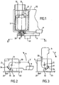
- a electric motor 1 is arranged in a housing 2 fixed on a support 20.
- the attachment of the housing 2 to the support 20 is ensured by pins 21 of the housing, which are crimped into holes in the support 20.
- the electric motor 1 receives its electric power on metal tabs 10 and can rotate in both directions according to his diet.
- the output shaft 11 of said motor 1 carries a latch 3 which it rotates between the two positions shown respectively in Figures 2 and 3.
- the position shown in the Figure 2 is the latch locking position 3, in which it maintains the flap 4 in the closed position, while the position shown in Figure 3 is its unlocked position.
- Engine 1 drives the latch in the direction symbolized by the arrow V for bring it from its unlocking position to its lock and in the opposite direction represented by arrow D to bring it to its unlocked position.
- a quarter-turn rotation of the motor ensures passage of the latch 3 from one to the other of its positions.
- the locking device according to the invention can be used on any support of any orientation.
- positioning means ensure so keeping the latch in each of its two positions so to ensure the stability of these positions.
- the positioning means are consist of an elastic tongue 31 secured to the latch and a finger 32 fixed carried by the housing 2.
- the tongue 31 consists of a thin-walled loop connected to latch 3 by its two ends.
- a V 34 notch is made in the thin wall of the tongue 31 in order to facilitate its deformation.
- the tongue 31 is in press against finger 32 in each of the locking positions and for unlocking the latch 3.
- the tongue 31 is, for each position of the latch, arranged on the suitable side of finger 32 so that said finger 32 either on the path of said tongue 31, if the latch tends to turn towards its other position.
- the tongue 31 deforms in order to pass over it of finger 32 and resumes its initial shape as soon as it has exceeded said finger.
- the electric motor used in the device lock according to the invention is a low power motor: the only one effort it has to provide is that allowing the deformation of the tongue 31 and enabling the inertia of the latch 3 to be overcome. For this purpose an engine developing a mechanical power of at most 10 watts is sufficient.
- Such motors are very inexpensive and the device for locking according to the invention can thus be offered on one side reasonable since, in addition, it does not require a housing gear.
- the latch 3 also carries a boss 33 intended to allow external mechanical action on the latch in the case of failure of the electrical installation or the engine.
- This boss can be arranged so as to be accessible from inside the vehicle, for example from inside the luggage compartment if the device locking device according to the invention is used on the fuel door. he can also be arranged so that it is accessible from a lock cylinder.
- the elastic tab can be fixed while the latch wears a finger.
- the tongue could also be a simple flat tongue arranged perpendicular to the latch surface.
- Other forms of positioning means can also be implemented, such as springs.
Landscapes
- Physics & Mathematics (AREA)
- Electromagnetism (AREA)
- Lock And Its Accessories (AREA)
Claims (10)
- Verriegelungsvorrichtung mit einem Betätigungsmittel, welches einen Elektromotor (1) in Betrieb setzt, dadurch gekennzeichnet, daß der Elektromotor (1) eine geringe Leistung aufweist und auf seiner Welle (11) einen Riegel (3) trägt, den er in Drehung versetzt zwischen zwei Positionen, die als Verriegelungsposition und Entriegelungsposition bezeichnet werden, wobei Positionierungsmittel (31, 32) dafür sorgen, daß der Riegel (3) jeweils in einer der zwei Positionen verbleibt.
- Verriegelungsvorrichtung nach Anspruch 1, dadurch gekennzeichnet, daß die Positionierungsmittel gebildet sind aus einer elastischen Zunge (31) und einem Finger (32), der mit der Zunge zusammenwirkt, wobei eines von beiden feststehend ist und das andere fest mit dem Riegel (3) verbunden ist.
- Verriegelungsvorrichtung nach Anspruch 2, dadurch gekennzeichnet, daß sich die Zunge (31) sowohl in der Verriegelungsposition als auch in der Entriegelungsposition des Riegels (3) an dem Finger (32) abstützt, wobei sich die Zunge (31) in jeder der genannten Positionen jeweils auf der geeigneten Seite des Fingers (32) befindet, damit sich, beim Übergang von der Verriegelungsposition in die Entriegelungsposition oder umgekehrt, der Finger (32) in der Bahn der Zunge (31) befindet oder umgekehrt.
- Verriegelungsvorrichtung nach einem der Ansprüche 2 oder 3, bei dem die Zunge (31) fest mit dem Riegel (3) verbunden ist, dadurch gekennzeichnet, daß die Zunge (31) aus einer Schlaufe mit geringer Wandstärke besteht, deren Enden mit dem Riegel (3) verbunden sind.
- Verriegelungsvorrichtung nach einem der Ansprüche 2 bis 4, dadurch gekennzeichnet, daß in der Wand der Zunge (31) eine Ausnehmung (34) vorgesehen ist, um die Verformung der Zunge (31) zu erleichtern.
- Verriegelungsvorrichtung nach Anspruch 5, dadurch gekennzeichnet, daß die Ausnehmung (34) V-förmig ist.
- Verriegelungsvorrichtung nach Anspruch 1, dadurch gekennzeichnet, daß die Positionierungsmittel wenigstens eine Feder aufweisen.
- Verriegelungsvorrichtung nach einem der Ansprüche 1 bis 7, dadurch gekennzeichnet, daß der Riegel (3) einen Höcker (33) aufweist, der im Falle eines Versagens der elektrischen Einrichtung oder des Motors einen mechanischen Eingriff von Außen gestattet.
- Verriegelungsvorrichtung nach einem der Ansprüche 1 bis 8, dadurch gekennzeichnet, daß der Motor (1) in beide Richtungen, je nach seiner Stromversorgung, drehen kann.
- Verriegelungsvorrichtung nach Anspruch 9, dadurch gekennzeichnet, daß ein Übergang des Riegels von einer Position in die andere durch eine Viertelumdrehung des Motors gewährleistet ist.
Applications Claiming Priority (2)
| Application Number | Priority Date | Filing Date | Title |
|---|---|---|---|
| FR9700481 | 1997-01-17 | ||
| FR9700481A FR2758584B1 (fr) | 1997-01-17 | 1997-01-17 | Dispositif de verrouillage/deverrouillage comportant un actionneur de faible cout |
Publications (2)
| Publication Number | Publication Date |
|---|---|
| EP0854260A1 EP0854260A1 (de) | 1998-07-22 |
| EP0854260B1 true EP0854260B1 (de) | 2003-03-26 |
Family
ID=9502713
Family Applications (1)
| Application Number | Title | Priority Date | Filing Date |
|---|---|---|---|
| EP19970403023 Expired - Lifetime EP0854260B1 (de) | 1997-01-17 | 1997-12-12 | Ver-/Entriegelungsvorrichtung mit preiswertem Betätiger |
Country Status (4)
| Country | Link |
|---|---|
| EP (1) | EP0854260B1 (de) |
| DE (1) | DE69720178T2 (de) |
| ES (1) | ES2196280T3 (de) |
| FR (1) | FR2758584B1 (de) |
Families Citing this family (5)
| Publication number | Priority date | Publication date | Assignee | Title |
|---|---|---|---|---|
| NZ520857A (en) * | 2002-08-19 | 2005-05-27 | Neil Richard Hingston | Electric lock |
| US7900979B2 (en) * | 2003-06-27 | 2011-03-08 | Illinois Tool Works, Inc. | Low power consumption lock for appliance latch |
| US7252311B2 (en) * | 2003-09-17 | 2007-08-07 | Hartwell Corporation | Motor driven latch |
| DE202012002858U1 (de) * | 2012-03-20 | 2013-06-24 | Kiekert Ag | Kraftfahrzeugtürverschluss |
| CN105672774A (zh) * | 2016-02-01 | 2016-06-15 | 赵百华 | 一种房门防盗暗锁 |
Family Cites Families (5)
| Publication number | Priority date | Publication date | Assignee | Title |
|---|---|---|---|---|
| US3722938A (en) * | 1971-03-22 | 1973-03-27 | Sargent & Co | Emergency exit door unlatching actuator |
| DE3412959A1 (de) * | 1984-04-06 | 1985-10-24 | Neiman GmbH, 5657 Haan | Vorrichtung zum schliessen einer kraftfahrzeugtuer |
| FR2592912B1 (fr) * | 1986-01-10 | 1990-11-02 | Brunam Controle Sarl | Dispositif de securite pour le verrouillage et le deverrouillage a distance d'un organe mobile, notamment d'une barre antipanique. |
| DE8808718U1 (de) * | 1988-07-07 | 1989-11-02 | Schmale GmbH & Co KG, 5880 Lüdenscheid | Schloß mit Drehriegel |
| DE4429475A1 (de) * | 1994-08-19 | 1996-02-22 | Reiner G Szperkowski | KFZ - Tür |
-
1997
- 1997-01-17 FR FR9700481A patent/FR2758584B1/fr not_active Expired - Fee Related
- 1997-12-12 ES ES97403023T patent/ES2196280T3/es not_active Expired - Lifetime
- 1997-12-12 EP EP19970403023 patent/EP0854260B1/de not_active Expired - Lifetime
- 1997-12-12 DE DE1997620178 patent/DE69720178T2/de not_active Expired - Fee Related
Also Published As
| Publication number | Publication date |
|---|---|
| FR2758584B1 (fr) | 1999-03-26 |
| DE69720178T2 (de) | 2003-10-23 |
| FR2758584A1 (fr) | 1998-07-24 |
| DE69720178D1 (de) | 2003-04-30 |
| EP0854260A1 (de) | 1998-07-22 |
| ES2196280T3 (es) | 2003-12-16 |
Similar Documents
| Publication | Publication Date | Title |
|---|---|---|
| EP0059658B1 (de) | Schloss, insbesondere für Fahrzeugtüren | |
| EP0082761B1 (de) | Kraftfahrzeugtürschloss | |
| EP0828911B1 (de) | Türschloss eines fahrzeuges | |
| FR3006405A1 (fr) | Ensemble comportant un support fixe, des poulies, une courroie et un tendeur de courroie. | |
| FR2794161A1 (fr) | Clef electronique pour vehicule automobile | |
| FR2565171A1 (fr) | Dispositif d'actionnement de capote rabattable | |
| EP0645511B1 (de) | Schloss für eine Kraftfahrzeugtür | |
| EP0957293A1 (de) | Elektromagnetische Betätigungseinrichtung mit Gewindespindelantrieb | |
| EP0854260A1 (de) | Ver-/Entriegelungsvorrichtung mit preiswertem Betätiger | |
| FR2753738A1 (fr) | Module de serrure electrique pour le coffre d'un vehicule automobile | |
| WO2019141934A1 (fr) | Dispositif de controle de volet notamment pour vehicule automobile, et cadre comprenant un tel dispositif | |
| EP0243214B1 (de) | Verriegelungsvorrichtung verwendbar als Diebstahlsicherung für ein elektrisches Kraftfahrzeugtürschloss und übereinstimmendes Schloss | |
| EP0433103B1 (de) | Elektrische Steuervorrichtung für einen schwenkbaren, an zwei Endpunkten seiner Bewegung frei gehaltenen Hebel und Schloss mit dieser Vorrichtung | |
| FR2689171A1 (fr) | Dispositif de commande d'un vantail de porte ou portail. | |
| FR2678314A1 (fr) | Dispositif d'assistance a la fermeture pour portiere de vehicule automobile. | |
| FR2769037A1 (fr) | Dispositif de verrouillage comportant un doigt de transmission commande par came | |
| EP0791708B1 (de) | Verriegelungsvorrichtung eines Fahrzeugsflügels mit Mitteln zur Blockierung der Betätigungsgestange | |
| EP0102263B1 (de) | Elektrisches Schloss für Kraftfahrzeugtür | |
| FR2906291A1 (fr) | Serrure motorisee a double came pour un volet ouvrant de vehicule automobile ou analogue. | |
| FR3122894A1 (fr) | Serrure de portière de véhicule | |
| FR2781835A1 (fr) | Module de serrure electrique pour un coffre de vehicule | |
| FR2766441A1 (fr) | Antivol electrique comportant des moyens complementaires de blocage du pene | |
| WO2005124072A1 (fr) | Dispositif d’assistance a l’ouverture/fermeture d’un ouvrant | |
| FR2841928A1 (fr) | Module de serrure electrique pour le coffre d'un vehicule automobile | |
| FR3069217A1 (fr) | Boite a gants |
Legal Events
| Date | Code | Title | Description |
|---|---|---|---|
| PUAI | Public reference made under article 153(3) epc to a published international application that has entered the european phase |
Free format text: ORIGINAL CODE: 0009012 |
|
| AK | Designated contracting states |
Kind code of ref document: A1 Designated state(s): DE ES GB IT |
|
| AX | Request for extension of the european patent |
Free format text: AL;LT;LV;MK;RO;SI |
|
| 17P | Request for examination filed |
Effective date: 19980828 |
|
| AKX | Designation fees paid |
Free format text: DE ES GB IT |
|
| RBV | Designated contracting states (corrected) |
Designated state(s): DE ES GB IT |
|
| 17Q | First examination report despatched |
Effective date: 20010515 |
|
| RAP1 | Party data changed (applicant data changed or rights of an application transferred) |
Owner name: VALEO SECURITE HABITACLE |
|
| GRAG | Despatch of communication of intention to grant |
Free format text: ORIGINAL CODE: EPIDOS AGRA |
|
| GRAG | Despatch of communication of intention to grant |
Free format text: ORIGINAL CODE: EPIDOS AGRA |
|
| GRAH | Despatch of communication of intention to grant a patent |
Free format text: ORIGINAL CODE: EPIDOS IGRA |
|
| GRAH | Despatch of communication of intention to grant a patent |
Free format text: ORIGINAL CODE: EPIDOS IGRA |
|
| GRAA | (expected) grant |
Free format text: ORIGINAL CODE: 0009210 |
|
| AK | Designated contracting states |
Designated state(s): DE ES GB IT |
|
| REG | Reference to a national code |
Ref country code: GB Ref legal event code: FG4D Free format text: NOT ENGLISH |
|
| REF | Corresponds to: |
Ref document number: 69720178 Country of ref document: DE Date of ref document: 20030430 Kind code of ref document: P |
|
| GBT | Gb: translation of ep patent filed (gb section 77(6)(a)/1977) |
Effective date: 20030513 |
|
| REG | Reference to a national code |
Ref country code: ES Ref legal event code: FG2A Ref document number: 2196280 Country of ref document: ES Kind code of ref document: T3 |
|
| PLBE | No opposition filed within time limit |
Free format text: ORIGINAL CODE: 0009261 |
|
| 26N | No opposition filed |
Effective date: 20031230 |
|
| PGFP | Annual fee paid to national office [announced via postgrant information from national office to epo] |
Ref country code: ES Payment date: 20081222 Year of fee payment: 12 |
|
| PGFP | Annual fee paid to national office [announced via postgrant information from national office to epo] |
Ref country code: IT Payment date: 20081219 Year of fee payment: 12 |
|
| PGFP | Annual fee paid to national office [announced via postgrant information from national office to epo] |
Ref country code: DE Payment date: 20081210 Year of fee payment: 12 |
|
| PGFP | Annual fee paid to national office [announced via postgrant information from national office to epo] |
Ref country code: GB Payment date: 20081204 Year of fee payment: 12 |
|
| GBPC | Gb: european patent ceased through non-payment of renewal fee |
Effective date: 20091212 |
|
| PG25 | Lapsed in a contracting state [announced via postgrant information from national office to epo] |
Ref country code: DE Free format text: LAPSE BECAUSE OF NON-PAYMENT OF DUE FEES Effective date: 20100701 |
|
| PG25 | Lapsed in a contracting state [announced via postgrant information from national office to epo] |
Ref country code: GB Free format text: LAPSE BECAUSE OF NON-PAYMENT OF DUE FEES Effective date: 20091212 |
|
| PG25 | Lapsed in a contracting state [announced via postgrant information from national office to epo] |
Ref country code: IT Free format text: LAPSE BECAUSE OF NON-PAYMENT OF DUE FEES Effective date: 20091212 |
|
| REG | Reference to a national code |
Ref country code: ES Ref legal event code: FD2A Effective date: 20110401 |
|
| PG25 | Lapsed in a contracting state [announced via postgrant information from national office to epo] |
Ref country code: ES Free format text: LAPSE BECAUSE OF NON-PAYMENT OF DUE FEES Effective date: 20110321 |
|
| PG25 | Lapsed in a contracting state [announced via postgrant information from national office to epo] |
Ref country code: ES Free format text: LAPSE BECAUSE OF NON-PAYMENT OF DUE FEES Effective date: 20091213 |