EP0854334A1 - Bac de réception de neige carbonique - Google Patents
Bac de réception de neige carbonique Download PDFInfo
- Publication number
- EP0854334A1 EP0854334A1 EP98400026A EP98400026A EP0854334A1 EP 0854334 A1 EP0854334 A1 EP 0854334A1 EP 98400026 A EP98400026 A EP 98400026A EP 98400026 A EP98400026 A EP 98400026A EP 0854334 A1 EP0854334 A1 EP 0854334A1
- Authority
- EP
- European Patent Office
- Prior art keywords
- tank
- injection
- injector
- carbon dioxide
- container
- Prior art date
- Legal status (The legal status is an assumption and is not a legal conclusion. Google has not performed a legal analysis and makes no representation as to the accuracy of the status listed.)
- Withdrawn
Links
- CURLTUGMZLYLDI-UHFFFAOYSA-N Carbon dioxide Chemical compound O=C=O CURLTUGMZLYLDI-UHFFFAOYSA-N 0.000 title claims abstract description 90
- 229910002092 carbon dioxide Inorganic materials 0.000 title claims abstract description 34
- 239000001569 carbon dioxide Substances 0.000 title claims abstract description 30
- 239000007788 liquid Substances 0.000 claims abstract description 22
- 238000002347 injection Methods 0.000 claims description 33
- 239000007924 injection Substances 0.000 claims description 33
- 235000011089 carbon dioxide Nutrition 0.000 claims description 25
- 238000003860 storage Methods 0.000 claims description 12
- 238000009434 installation Methods 0.000 claims description 8
- 230000015572 biosynthetic process Effects 0.000 claims description 4
- 238000009826 distribution Methods 0.000 claims description 3
- 238000005304 joining Methods 0.000 claims description 2
- 239000007789 gas Substances 0.000 description 5
- 238000000859 sublimation Methods 0.000 description 3
- 230000008022 sublimation Effects 0.000 description 3
- 238000004519 manufacturing process Methods 0.000 description 2
- 239000000725 suspension Substances 0.000 description 2
- 238000004026 adhesive bonding Methods 0.000 description 1
- 230000008878 coupling Effects 0.000 description 1
- 238000010168 coupling process Methods 0.000 description 1
- 238000005859 coupling reaction Methods 0.000 description 1
- 230000007423 decrease Effects 0.000 description 1
- 239000002245 particle Substances 0.000 description 1
- 238000005057 refrigeration Methods 0.000 description 1
- 238000005204 segregation Methods 0.000 description 1
- 238000000926 separation method Methods 0.000 description 1
- 239000000243 solution Substances 0.000 description 1
Images

Classifications
-
- F—MECHANICAL ENGINEERING; LIGHTING; HEATING; WEAPONS; BLASTING
- F25—REFRIGERATION OR COOLING; COMBINED HEATING AND REFRIGERATION SYSTEMS; HEAT PUMP SYSTEMS; MANUFACTURE OR STORAGE OF ICE; LIQUEFACTION SOLIDIFICATION OF GASES
- F25D—REFRIGERATORS; COLD ROOMS; ICE-BOXES; COOLING OR FREEZING APPARATUS NOT OTHERWISE PROVIDED FOR
- F25D3/00—Devices using other cold materials; Devices using cold-storage bodies
- F25D3/12—Devices using other cold materials; Devices using cold-storage bodies using solidified gases, e.g. carbon-dioxide snow
- F25D3/125—Movable containers
-
- C—CHEMISTRY; METALLURGY
- C01—INORGANIC CHEMISTRY
- C01B—NON-METALLIC ELEMENTS; COMPOUNDS THEREOF; METALLOIDS OR COMPOUNDS THEREOF NOT COVERED BY SUBCLASS C01C
- C01B32/00—Carbon; Compounds thereof
- C01B32/50—Carbon dioxide
- C01B32/55—Solidifying
Definitions
- the present invention relates to a container for receiving carbon dioxide snow of the type comprising, on the one hand, injection means adapted to cooperate with an injector connected to a source of liquid CO 2 and to allow the injection of carbon dioxide snow into the container. , and, on the other hand, in the upper face of the tank, means for evacuating the gaseous CO 2 formed during said injection.
- Such bins are particularly intended storage and transport of products fresh food.
- bins are sometimes removable and have an open upper face to receive the loading of dry ice from a dry ice container in bulk, or directly a carbon dioxide snow projection torch.
- This type of loading is delicate, not very rational and causes significant losses in dry ice. In addition, it does not allow the quantity of dry ice to specific needs that may require conservation of particular products.
- the tank described in this last document comprises, on the one hand, an injection ramp comprising injection or expansion ports for liquid CO 2 , which can be connected to a liquid CO 2 injector, and a deflector.
- an injection ramp comprising injection or expansion ports for liquid CO 2 , which can be connected to a liquid CO 2 injector, and a deflector.
- it includes in its upper surface a grid for evacuating the gaseous CO 2 produced during the formation of the carbon dioxide snow.
- This grid prevents the carbon dioxide snow formed from escaping from the tank and allows, after loading the tank, the evacuation of the gaseous CO 2 formed by sublimation of the carbon dioxide snow.
- the injection ramp is arranged along a lateral face of the tank and allows a relatively uniform filling thereof. The main drawback of such an arrangement is its high cost.
- Another embodiment described in the same document comprises an injection box which can be adapted directly to a loading face of a container.
- the tank described also has a grid for evacuating CO 2 gas and retaining dry ice, mounted in the upper face of the tank.
- This embodiment has the drawback of requiring the production of as many injection boxes as there are different sizes of tanks.
- the object of the present invention is to provide a tank which, on the one hand, allows rapid, modular loading, requiring minimum handling and reducing CO 2 losses, and, on the other hand, is simple to carry out and therefore reduced production cost.
- the subject of the invention is a container of the aforementioned type, characterized in that the injection means are adapted to orient the injection of dry ice approximately tangentially to a side wall of the container so as to create a vortex in the tank, and in that the means for evacuating the gaseous CO 2 produced during the injection of carbon dioxide snow are located in the central region of said vortex.
- the subject of the invention is also a low temperature storage enclosure of products, of the type with a storage volume thermally insulated and at least one snow bin carbonic suitable for refrigerating this volume, characterized in that the bin is a bin as defined above.
- the subject of the invention is finally an installation for the conservation at low temperature of products, of the type comprising an enclosure for the conservation at low temperature of products comprising a storage volume and at least one container for receiving dry ice adapted to refrigerate this volume, a source of liquid CO 2 under pressure, and an injector connected to this source, adapted to be connected to the tank and provided with a distribution valve connected to control means, characterized in that the enclosure is an enclosure such that defined above.
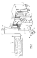
- the installation shown in FIG. 1 comprises an enclosure 1 for low-temperature storage of products as described in the document EP-A-337 860 mentioned above, a device 3 for loading dry ice and a source 5 of liquid CO 2 .
- the liquid CO 2 is contained in a tank 7 under determined pressure and temperature conditions, maintained by a refrigeration unit 9, typically between 18 and 20 bars relative and at -20 ° C.
- Enclosure 1 is an insulated container of mobile parallelepiped shape on casters 12. It includes a front access door not shown, and a container 11 for receiving the dry ice.
- the tray 11, parallelepiped and flat in shape, is consisting of a bowl 14 and a cover 16. It is suspended, by means of fixing lugs 13 evenly distributed on the side faces of the bowl and, for example, a bolting system, in the upper part of the inner chamber 15 of enclosure 1. The lower part of this room 15 forms a storage volume for products thermally insulated.
- Enclosure 1 further includes a screen thermal 17 removable, in the form of a horizontal plate, suspended from the tank 11 by means of lugs 19 ( Figure 2). This screen extends away from the underside of the tray 11 and separates the latter from the storage volume.
- the front face of the tank 11 is provided with a dry ice injection port 21, suitable to receive the head of a snow injector carbonic. This hole is adjacent to the face left side of bin 11, which is one of two large side faces of the tank.
- a magnetic plate 23 is also fixed, by gluing or otherwise, to near orifice 17 to allow the temporary securing of the tank and a injector dry ice.
- the upper face of the tank 11 has a circular orifice 25 for evacuating the gaseous CO 2 formed during the injection of carbon dioxide snow.
- This orifice 25 also serves as a means of evacuation of the gaseous CO2 formed during the sublimation of the carbon dioxide snow.
- the loading device 3 comprises an injector 31 of dry ice and an articulated awning structure 23.
- This structure 27 is provided with two deployable lateral leaves 29. It is intended to be positioned opposite the front face of the enclosure 1, which is the loading face in dry ice.
- the injector 31 is suspended by means 33 of elastic suspension from a gantry 35 secured to the deployed structure 27.
- the suspension means 33 can be moved along the gantry 35 by means of a carriage 37.
- the structure 27 is also connected to a discharge device 39 comprising a blower.
- the structure 27, as described in the aforementioned application EP-A-631 096, is intended to form a receptacle for confining the CO 2 gas formed during the loading of the tank with carbon dioxide snow.
- a pipe 41 for supplying liquid CO 2 leaves from the reservoir 7. It is extended by a hose 43 connected to the injector 31.
- the injector 31 in the form of a pistol, is a dry ice injector. Its head has means for expanding the liquid CO 2 and for forming carbon dioxide snow, namely a calibrated orifice (not visible in the drawings) and an outlet nozzle 45 of cylindrical shape with horizontal axis.
- the injector 31 further comprises a distribution solenoid valve, not shown, which makes it possible to dose the quantity of expanded liquid CO 2 and therefore of the carbon dioxide snow formed.
- the solenoid valve is connected by suitable wiring 47 to control means 49.
- a magnetic socket 51 is fixed on the outer surface of the nozzle 45, parallel to its main axis. It ensures solidarity temporary injector 31 and tank 11 cooperating with the magnetic plate 23.
- the carriage 37 and the means 33 allow bring the injector 31 to the right of the orifice 21 and insert nozzle 45 into the tank through this orifice.
- Magnetic plate 23 and socket magnetized 51 are positioned so as to come then in contact and, thus, ensure the joining temporary injector 31 and tank 11.
- the start and duration of loading are controlled via the solenoid valve by means 49 of ordered.
- the loading of the bin is illustrated by the Figures 3 and 4.
- the liquid CO 2 is expanded in the nozzle 45, which produces a carbon dioxide snow jet substantially tangent to the left lateral face of the container 11.
- the carbon dioxide snow impacts the rear face of the container, then is deflected along the latter until it impacts the right side face of the tank 11.
- the jet is then deflected along this right side face. It then impacts the front face of the tank 11 at its right end, before being deflected again towards the left end of this front face, where it meets the jet emerging from the nozzle 45.
- the gaseous CO 2 formed is concentrated in the central part of the vortex and rises from it.
- the discharge port 25 was placed in the region of the vortex centers for the range of injection pressures selected.
- the arrows in FIG. 4 show the evacuation route out of the gaseous CO 2 tank. This configuration eliminates the presence of a carbon dioxide retaining grid, since the segregation of gases and snow particles occurs naturally within the vortex.
- the container according to the invention therefore allows to obtain a satisfactory filling of the snow container carbon dioxide, as shown in Figure 4.
- the socket 51 and the plate 23 are adapted so that, on the one hand, the decline in the injector 31 when loading the tank does not cause not the separation of the tank 11 and the injector 31, and on the other hand, so that an operator is capable to separate the tank 11 and the injector 31 manually.
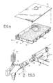
- FIG. 5 illustrates another mode of realization of the invention, which differs from the previous one with the following points.
- the tank comprises means 53 for connection to an injector 55 of liquid CO 2 , of the "quick coupling" type, and means for injecting carbon dioxide snow into the tank comprising means for expanding liquid CO 2 and for forming snow. carbonic.
- These means include a calibrated orifice for CO 2 expansion (not visible in the drawing), and a cylindrical nozzle 57 for injection into the bowl 14 of the dry ice formed.
- the calibrated orifice and the nozzle 57 are therefore integral with the tank 11.
- the nozzle 57 is identical to the nozzle 45 of Figures 1 to 3 and oriented in the same way.
- the injector 55 includes a device for manual locking / unlocking which allows temporarily attach to the connection means 53.
- the injector 55 has a manual tap 61 opening / closing downstream of the solenoid valve of the injector. This tap 61 is mechanically coupled to device 59 so as not to allow opening from the tap only when the injector 55 and the tank are properly secured, as described in the request mentioned above EP-A-631 096.
- the other elements of the tank 11 of the injector 55 are identical in all respects to those of the previous embodiment.
- the tank 11 and the injector 55 of FIG. 5 can also be incorporated into an enclosure and an installation as described above.
- the injector 55 is secured thanks to the device 59, and the opening of the gun solenoid valve is controlled by the control means 49.
- the filling mode is then identical to the one described above, creating also a vortex, and therefore presenting the same advantages.
- the invention makes it possible to provide a fast, efficient, modular injection of dry ice, with easy implementation and low CO 2 losses.
- the tank is of reduced cost since it does not have an injection rail or an evacuation grid. It can also be charged by common liquid CO 2 or carbon dioxide snow injectors.
Landscapes
- Chemical & Material Sciences (AREA)
- Engineering & Computer Science (AREA)
- Chemical Kinetics & Catalysis (AREA)
- Organic Chemistry (AREA)
- Inorganic Chemistry (AREA)
- Combustion & Propulsion (AREA)
- Physics & Mathematics (AREA)
- Mechanical Engineering (AREA)
- Thermal Sciences (AREA)
- General Engineering & Computer Science (AREA)
- Carbon And Carbon Compounds (AREA)
Abstract
Description
- les moyens d'injection comprennent un orifice de réception d'une buse de détente de CO2 liquide et de formation de neige carbonique solidaire de la tête de l'injecteur,
- les moyens d'injection comprennent des moyens de raccordement à l'injecteur, reliés à une buse de détente de CO2 liquide et de génération de neige carbonique, cette buse étant solidaire du bac,
- des moyens de solidarisation temporaire sont prévus pour positionner l'injecteur sur le bac,
- les moyens de solidarisation temporaire comprennent un dispositif de verrouillage/déverrouillage manuel,
- les moyens de solidarisation comprennent un système à aimant,
- les moyens d'évacuation sont constitués par un orifice, notamment circulaire,
- le bac est parallélépipédique et les moyens d'injection sont adjacents et parallèles à une des grandes faces latérales du bac.
- la figure 1 est une vue schématique d'une installation de conservation de produits frais selon l'invention,
- la figure 2 est une vue en perspective du bac de réception de neige carbonique de l'installation de la figure 1,
- les figures 3 et 4 sont des vues en perspective éclatée illustrant le remplissage du bac de la figure 2,
- la figure 5 est une vue schématique en perspective, avec arrachement, illustrant un autre mode de réalisation d'un bac selon l'invention.
Claims (10)
- Bac (11) de réception de neige carbonique, du type comprenant, d'une part, des moyens (21 ; 53, 57) d'injection adaptés pour coopérer avec un injecteur (31) relié à une source (5) de CO2 liquide et permettre l'injection de neige carbonique dans le bac (11), et, d'autre part, dans la face supérieure du bac (11), des moyens (25) d'évacuation du CO2 gazeux formé lors de ladite injection, caractérisé en ce que les moyens (21 ; 53, 57) d'injection sont adaptés pour orienter l'injection de neige carbonique à peu près tangentiellement à une paroi latérale du bac (11) de manière à créer un tourbillon dans le bac, et en ce que les moyens (21 ; 53, 57) d'évacuation du CO2 gazeux produit lors de l'injection de neige carbonique sont localisés dans la région centrale dudit tourbillon.
- Bac selon la revendication 1, caractérisé en ce que les moyens (21) d'injection comprennent un orifice (21) de réception d'une buse (45) de détente de CO2 liquide et de formation de neige carbonique solidaire de la tête de l'injecteur (31).
- Bac selon la revendication 1, caractérisé en ce que les moyens (53, 57) d'injection comprennent des moyens (53) de raccordement à l'injecteur (31), reliés à une buse (57) de détente de CO2 liquide et de formation de neige carbonique, cette buse étant solidaire du bac (11).
- Bac selon l'une quelconque des revendications 1 à 3, caractérisé en ce qu'il comporte des moyens (23, 51 ; 59) de solidarisation temporaire prévus pour positionner l'injecteur (31) sur le bac (11).
- Bac selon la revendication 4, caractérisé en ce que les moyens (59) de solidarisation temporaire comprennent un dispositif (59) de verrouillage/déverrouillage manuel.
- Bac selon les revendications 3 et 5 prises ensemble, caractérisé en ce que les moyens (23, 51) de solidarisation comprennent un système (23, 51) à aimant.
- Bac selon l'une quelconque des revendications 1 à 6, caractérisé en ce que les moyens (25) d'évacuation sont constitués par un orifice (25), notamment circulaire.
- Bac selon l'une quelconque des revendications 1 à 7, caractérisé en ce que le bac (11) est parallélépipédique et en ce que les moyens (21 ; 53, 57) d'injection sont adjacents et parallèles à une des grandes faces latérales du bac (11).
- Enceinte (3) de conservation à basse température de produits, du type comportant un volume de stockage thermiquement isolé et au moins un bac (11) de neige carbonique adapté pour réfrigérer ce volume, caractérisée en ce que le bac (11) est un bac selon l'une quelconque des revendications 1 à 8.
- Installation de conservation à basse température de produits du type comprenant, une enceinte (3) de conservation à basse température de produits comportant un volume de stockage thermiquement isolé et au moins un bac (11) de réception de neige carbonique adapté pour réfrigérer ce volume, une source (5) de CO2 liquide sous pression, et un injecteur (31) relié à cette source, adapté pour être relié au bac et muni d'une vanne de distribution reliée à des moyens (49) de commande, caractérisée en ce que l'enceinte (3) est conforme à la revendication 9.
Applications Claiming Priority (2)
| Application Number | Priority Date | Filing Date | Title |
|---|---|---|---|
| FR9700531A FR2758620B1 (fr) | 1997-01-20 | 1997-01-20 | Bac de reception de neige carbonique, et son application a une enceinte et une installation de conservation de produits |
| FR9700531 | 1997-01-20 |
Publications (1)
| Publication Number | Publication Date |
|---|---|
| EP0854334A1 true EP0854334A1 (fr) | 1998-07-22 |
Family
ID=9502762
Family Applications (1)
| Application Number | Title | Priority Date | Filing Date |
|---|---|---|---|
| EP98400026A Withdrawn EP0854334A1 (fr) | 1997-01-20 | 1998-01-08 | Bac de réception de neige carbonique |
Country Status (2)
| Country | Link |
|---|---|
| EP (1) | EP0854334A1 (fr) |
| FR (1) | FR2758620B1 (fr) |
Cited By (13)
| Publication number | Priority date | Publication date | Assignee | Title |
|---|---|---|---|---|
| FR2829567A1 (fr) * | 2001-09-07 | 2003-03-14 | Olivo | Dispositif d'alimentation automatique pour compartiment refrigerant d'un conteneur isotherme |
| FR2839774A1 (fr) * | 2002-05-17 | 2003-11-21 | Olivo | Reservoir cryogenique a diffusion adaptable pour conteneur isotherme |
| FR2891354A1 (fr) * | 2005-09-28 | 2007-03-30 | Air Liquide | Receptacle de neige carbonique a double compartiment pour conteneurs isothermes |
| FR2891899A1 (fr) * | 2005-10-12 | 2007-04-13 | Air Liquide | Systeme d'injection de neige carbonique dans des conteneurs isothermes et conteneurs associes |
| US9291296B2 (en) | 2012-11-06 | 2016-03-22 | Polar Tech Industries, Inc. | Blowback shield for carbon dioxide discharge horn |
| CN106642875A (zh) * | 2017-02-15 | 2017-05-10 | 广州鲜之源生态冷链技术有限公司 | 一种利用干冰为冷源的保鲜包 |
| US10330260B2 (en) | 2013-12-05 | 2019-06-25 | Praxair Technology, Inc. | Method and system for filling thermally insulated containers with liquid carbon dioxide |
| US10712072B2 (en) | 2016-07-11 | 2020-07-14 | Praxair Technology, Inc. | Transportable container, charger system, method and kit for generation of carbon dioxide snow block in-situ within the transportable container for preservation of items stored therewithin |
| WO2020186337A1 (fr) * | 2019-03-20 | 2020-09-24 | Cryologistics Refrigeration Technologies Ltd. | Système de réfrigération passif utilisant de la neige carbonique |
| EP3728966A1 (fr) * | 2017-12-20 | 2020-10-28 | Praxair Technology, Inc. | Procédés de préchargement de neige carbonique |
| US11248838B2 (en) | 2016-07-11 | 2022-02-15 | Praxair Technology, Inc. | Transportable container, charger system, method and kit for generation of carbon dioxide snow block in-situ within the transportable container for preservation of items stored there within |
| US11352262B2 (en) | 2017-12-18 | 2022-06-07 | Praxair Technology, Inc. | Methods for automatic filling, charging and dispensing carbon dioxide snow block |
| US11384904B2 (en) | 2013-12-05 | 2022-07-12 | Praxair Technology, Inc. | Method and system for filling thermally insulated containers with liquid carbon dioxide |
Citations (4)
| Publication number | Priority date | Publication date | Assignee | Title |
|---|---|---|---|---|
| US2893216A (en) * | 1956-02-01 | 1959-07-07 | Gen Dynamics Corp | Method of refrigerating a finelydivided material |
| FR2253193A1 (en) * | 1973-12-03 | 1975-06-27 | Air Liquide | Refrigeration of prods partic food prods - using carbon dioxide snow |
| US4299429A (en) * | 1980-02-13 | 1981-11-10 | Franklin Jr Paul R | Cooler with inclined upper CO2 cooled surface |
| EP0631096A1 (fr) * | 1993-06-23 | 1994-12-28 | Carboxyque Francaise | Procédé de conservation à basse température de produits dans une enceinte isolée, installation pour la mise en oeuvre du procédé, enceinte isolée et bac pour une telle enceinte |
Family Cites Families (2)
| Publication number | Priority date | Publication date | Assignee | Title |
|---|---|---|---|---|
| CA1319347C (fr) | 1988-04-08 | 1993-06-22 | Claude Gibot | Conteneur isotherme a reservoir de produit refrigerant et application au transport de produits frais |
| FR2696158B1 (fr) | 1992-09-29 | 1994-11-10 | Carboxyque Francaise | Conteneur isotherme, notamment pour le transport de produits frais ou surgelés. |
-
1997
- 1997-01-20 FR FR9700531A patent/FR2758620B1/fr not_active Expired - Fee Related
-
1998
- 1998-01-08 EP EP98400026A patent/EP0854334A1/fr not_active Withdrawn
Patent Citations (4)
| Publication number | Priority date | Publication date | Assignee | Title |
|---|---|---|---|---|
| US2893216A (en) * | 1956-02-01 | 1959-07-07 | Gen Dynamics Corp | Method of refrigerating a finelydivided material |
| FR2253193A1 (en) * | 1973-12-03 | 1975-06-27 | Air Liquide | Refrigeration of prods partic food prods - using carbon dioxide snow |
| US4299429A (en) * | 1980-02-13 | 1981-11-10 | Franklin Jr Paul R | Cooler with inclined upper CO2 cooled surface |
| EP0631096A1 (fr) * | 1993-06-23 | 1994-12-28 | Carboxyque Francaise | Procédé de conservation à basse température de produits dans une enceinte isolée, installation pour la mise en oeuvre du procédé, enceinte isolée et bac pour une telle enceinte |
Cited By (21)
| Publication number | Priority date | Publication date | Assignee | Title |
|---|---|---|---|---|
| FR2829567A1 (fr) * | 2001-09-07 | 2003-03-14 | Olivo | Dispositif d'alimentation automatique pour compartiment refrigerant d'un conteneur isotherme |
| EP1291594A3 (fr) * | 2001-09-07 | 2003-03-19 | Olivo | Dispositif d'alimentation automatique pour compartiment réfrigérant d'un conteneur isotherme |
| FR2839774A1 (fr) * | 2002-05-17 | 2003-11-21 | Olivo | Reservoir cryogenique a diffusion adaptable pour conteneur isotherme |
| FR2891354A1 (fr) * | 2005-09-28 | 2007-03-30 | Air Liquide | Receptacle de neige carbonique a double compartiment pour conteneurs isothermes |
| WO2007036656A1 (fr) * | 2005-09-28 | 2007-04-05 | L'air Liquide Societe Anonyme Pour L'etude Et L'exploitation Des Procedes Georges Claude | Receptacle de neige carbonique a double compartiment pour conteneurs isothermes |
| FR2891899A1 (fr) * | 2005-10-12 | 2007-04-13 | Air Liquide | Systeme d'injection de neige carbonique dans des conteneurs isothermes et conteneurs associes |
| WO2007042727A1 (fr) * | 2005-10-12 | 2007-04-19 | L'Air Liquide, Société Anonyme pour l'Etude et l'Exploitation des Procédés Georges Claude | Systeme d'injection de neige carbonique dans des conteneurs isothermes et conteneurs associes |
| US9291296B2 (en) | 2012-11-06 | 2016-03-22 | Polar Tech Industries, Inc. | Blowback shield for carbon dioxide discharge horn |
| US11384904B2 (en) | 2013-12-05 | 2022-07-12 | Praxair Technology, Inc. | Method and system for filling thermally insulated containers with liquid carbon dioxide |
| US10330260B2 (en) | 2013-12-05 | 2019-06-25 | Praxair Technology, Inc. | Method and system for filling thermally insulated containers with liquid carbon dioxide |
| US10712072B2 (en) | 2016-07-11 | 2020-07-14 | Praxair Technology, Inc. | Transportable container, charger system, method and kit for generation of carbon dioxide snow block in-situ within the transportable container for preservation of items stored therewithin |
| US11248838B2 (en) | 2016-07-11 | 2022-02-15 | Praxair Technology, Inc. | Transportable container, charger system, method and kit for generation of carbon dioxide snow block in-situ within the transportable container for preservation of items stored there within |
| CN106642875A (zh) * | 2017-02-15 | 2017-05-10 | 广州鲜之源生态冷链技术有限公司 | 一种利用干冰为冷源的保鲜包 |
| CN106642875B (zh) * | 2017-02-15 | 2022-07-22 | 广州鲜之源生态冷链技术有限公司 | 一种利用干冰为冷源的保鲜包 |
| US11352262B2 (en) | 2017-12-18 | 2022-06-07 | Praxair Technology, Inc. | Methods for automatic filling, charging and dispensing carbon dioxide snow block |
| EP3728966A1 (fr) * | 2017-12-20 | 2020-10-28 | Praxair Technology, Inc. | Procédés de préchargement de neige carbonique |
| US11193708B2 (en) | 2017-12-20 | 2021-12-07 | Praxair Technology, Inc. | Methods for pre-charging carbon dioxide snow |
| EP3728966B1 (fr) * | 2017-12-20 | 2026-04-01 | Praxair Technology, Inc. | Méthode de pré-chargement de neige carbonique |
| WO2020186337A1 (fr) * | 2019-03-20 | 2020-09-24 | Cryologistics Refrigeration Technologies Ltd. | Système de réfrigération passif utilisant de la neige carbonique |
| EP3942236A4 (fr) * | 2019-03-20 | 2022-11-30 | Cryologistics Refrigeration Technologies Ltd. | Système de réfrigération passif utilisant de la neige carbonique |
| US12416440B2 (en) | 2019-03-20 | 2025-09-16 | Cryologistics Refrigeration Technologies Ltd. | Passive refrigeration system using carbon dioxide snow |
Also Published As
| Publication number | Publication date |
|---|---|
| FR2758620A1 (fr) | 1998-07-24 |
| FR2758620B1 (fr) | 1999-02-26 |
Similar Documents
| Publication | Publication Date | Title |
|---|---|---|
| EP0631096B1 (fr) | Procédé de conservation à basse température de produits dans une enceinte isolée, installation pour la mise en oeuvre du procédé, enceinte isolée et bac pour une telle enceinte | |
| EP0854334A1 (fr) | Bac de réception de neige carbonique | |
| FR2678527A1 (fr) | Appareil de stockage et de projection de billes de glace. | |
| EP1350743B1 (fr) | Procédé et dispositif de remplissage automatique d'un bac chauffant avec un produit solide | |
| EP0823600B1 (fr) | Conteneur isotherme avec réserve de frigories | |
| FR2734894A1 (fr) | Installation pour le maintien a basse temperature d'une enceinte mobile | |
| EP1033173B1 (fr) | Centrifugeuse à refroidissement par tube de Ranque | |
| EP0968395A2 (fr) | Chariot refrigere et installation de rechargement en agent refrigerant | |
| EP3592145B1 (fr) | Système et procédé de vitrification d'une substance biologique | |
| FR2851329A1 (fr) | Procede de maintien au froid d'aliments a bord d'aeronefs et moyen de mise en oeuvre | |
| EP0942244A1 (fr) | Dispositif brise-jet pour compartiment cryogénique de conteneur isothermique | |
| CH682390A5 (fr) | Conteneur pour le transport d'un matériau en état solide. | |
| WO2002028763A1 (fr) | Distributeur de boisson refrigeree equipe de deux moyens refrigerants | |
| EP3246642A1 (fr) | Réservoir cryogénique pour compartiment réfrigérant de conteneur isotherme | |
| EP1934537B1 (fr) | Réceptacle de neige carbonique a double compartiment pour conteneurs isothermes | |
| FR2891899A1 (fr) | Systeme d'injection de neige carbonique dans des conteneurs isothermes et conteneurs associes | |
| EP3094916A1 (fr) | Système de protection thermique pour un réservoir cryogénique d'engin spatial | |
| EP3948115A1 (fr) | Conteneur de transport de produits a une plage de temperature desiree | |
| EP1110042A1 (fr) | Procede de refroidissement en continu de produits et dispositif de refroidissement correspondant | |
| FR2751623A1 (fr) | Conteneur isotherme avec bac refrigerant | |
| FR2688394A1 (fr) | Vitrine refrigeree autonome. | |
| CH637757A5 (en) | Refrigeration enclosure | |
| FR2589220A1 (fr) | Perfectionnements de rampe pour ecrans fluides | |
| FR2835045A1 (fr) | Dispositif pour la conservation au frais de produits divers | |
| FR3031171A1 (fr) | Reservoir cryogenique pour compartiment refrigerant de conteneur isotherme |
Legal Events
| Date | Code | Title | Description |
|---|---|---|---|
| PUAI | Public reference made under article 153(3) epc to a published international application that has entered the european phase |
Free format text: ORIGINAL CODE: 0009012 |
|
| AK | Designated contracting states |
Kind code of ref document: A1 Designated state(s): AT BE CH DE DK ES FI FR GB GR IE IT LI LU MC NL PT SE |
|
| AX | Request for extension of the european patent |
Free format text: AL;LT;LV;MK;RO;SI |
|
| 17P | Request for examination filed |
Effective date: 19990122 |
|
| AKX | Designation fees paid |
Free format text: AT BE CH DE DK ES FI FR GB GR IE IT LI LU MC NL PT SE |
|
| RBV | Designated contracting states (corrected) |
Designated state(s): AT BE CH DE DK ES FI FR GB GR IE IT LI LU MC NL PT SE |
|
| 17Q | First examination report despatched |
Effective date: 20010411 |
|
| STAA | Information on the status of an ep patent application or granted ep patent |
Free format text: STATUS: THE APPLICATION IS DEEMED TO BE WITHDRAWN |
|
| 18D | Application deemed to be withdrawn |
Effective date: 20020201 |