EP0854335A2 - Procédé et dispositif pour la séparation et la purification de composés perfluorés - Google Patents
Procédé et dispositif pour la séparation et la purification de composés perfluorés Download PDFInfo
- Publication number
- EP0854335A2 EP0854335A2 EP98400067A EP98400067A EP0854335A2 EP 0854335 A2 EP0854335 A2 EP 0854335A2 EP 98400067 A EP98400067 A EP 98400067A EP 98400067 A EP98400067 A EP 98400067A EP 0854335 A2 EP0854335 A2 EP 0854335A2
- Authority
- EP
- European Patent Office
- Prior art keywords
- column
- product
- heavy
- heavy product
- introducing
- Prior art date
- Legal status (The legal status is an assumption and is not a legal conclusion. Google has not performed a legal analysis and makes no representation as to the accuracy of the status listed.)
- Withdrawn
Links
Images


Classifications
-
- B—PERFORMING OPERATIONS; TRANSPORTING
- B01—PHYSICAL OR CHEMICAL PROCESSES OR APPARATUS IN GENERAL
- B01D—SEPARATION
- B01D45/00—Separating dispersed particles from gases or vapours by gravity, inertia, or centrifugal forces
- B01D45/02—Separating dispersed particles from gases or vapours by gravity, inertia, or centrifugal forces by utilising gravity
-
- C—CHEMISTRY; METALLURGY
- C07—ORGANIC CHEMISTRY
- C07C—ACYCLIC OR CARBOCYCLIC COMPOUNDS
- C07C17/00—Preparation of halogenated hydrocarbons
- C07C17/38—Separation; Purification; Stabilisation; Use of additives
-
- B—PERFORMING OPERATIONS; TRANSPORTING
- B01—PHYSICAL OR CHEMICAL PROCESSES OR APPARATUS IN GENERAL
- B01D—SEPARATION
- B01D53/00—Separation of gases or vapours; Recovering vapours of volatile solvents from gases; Chemical or biological purification of waste gases, e.g. engine exhaust gases, smoke, fumes, flue gases, aerosols
- B01D53/002—Separation of gases or vapours; Recovering vapours of volatile solvents from gases; Chemical or biological purification of waste gases, e.g. engine exhaust gases, smoke, fumes, flue gases, aerosols by condensation
-
- B—PERFORMING OPERATIONS; TRANSPORTING
- B01—PHYSICAL OR CHEMICAL PROCESSES OR APPARATUS IN GENERAL
- B01D—SEPARATION
- B01D53/00—Separation of gases or vapours; Recovering vapours of volatile solvents from gases; Chemical or biological purification of waste gases, e.g. engine exhaust gases, smoke, fumes, flue gases, aerosols
- B01D53/005—Separation of gases or vapours; Recovering vapours of volatile solvents from gases; Chemical or biological purification of waste gases, e.g. engine exhaust gases, smoke, fumes, flue gases, aerosols by heat treatment
-
- B—PERFORMING OPERATIONS; TRANSPORTING
- B01—PHYSICAL OR CHEMICAL PROCESSES OR APPARATUS IN GENERAL
- B01D—SEPARATION
- B01D53/00—Separation of gases or vapours; Recovering vapours of volatile solvents from gases; Chemical or biological purification of waste gases, e.g. engine exhaust gases, smoke, fumes, flue gases, aerosols
- B01D53/02—Separation of gases or vapours; Recovering vapours of volatile solvents from gases; Chemical or biological purification of waste gases, e.g. engine exhaust gases, smoke, fumes, flue gases, aerosols by adsorption, e.g. preparative gas chromatography
- B01D53/04—Separation of gases or vapours; Recovering vapours of volatile solvents from gases; Chemical or biological purification of waste gases, e.g. engine exhaust gases, smoke, fumes, flue gases, aerosols by adsorption, e.g. preparative gas chromatography with stationary adsorbents
-
- C—CHEMISTRY; METALLURGY
- C01—INORGANIC CHEMISTRY
- C01B—NON-METALLIC ELEMENTS; COMPOUNDS THEREOF; METALLOIDS OR COMPOUNDS THEREOF NOT COVERED BY SUBCLASS C01C
- C01B9/00—General methods of preparing halides
- C01B9/08—Fluorides
-
- C—CHEMISTRY; METALLURGY
- C07—ORGANIC CHEMISTRY
- C07C—ACYCLIC OR CARBOCYCLIC COMPOUNDS
- C07C17/00—Preparation of halogenated hydrocarbons
- C07C17/38—Separation; Purification; Stabilisation; Use of additives
- C07C17/383—Separation; Purification; Stabilisation; Use of additives by distillation
Definitions
- the present invention relates to a method for separating and purifying perfluorocompounds.
- the invention also relates to a system for separating and purifying perfluorocompounds.
- the inventive method and system have particular applicability in semiconductor manufacturing, for example, in the treatment of an exhaust gas from a semiconductor processing tool.
- PFCs perfluorocompounds
- etching processes such as oxide, metal and dielectric etching steps.
- a gas or a plasma atmosphere selectively removes portions of a layer deposited on the substrate.
- Perfluorocompounds are also employed in deposition processes, such as silicon chemical vapor deposition (CVD), as well as in the cleaning of semiconductor processing chambers.
- Perfluorocompound gases used in the above-mentioned processes include, for example, carbon tetrafluoride (CF 4 ), hexafluoroethane (C 2 F 6 ), perafluoropropane (C 3 F 8 ), trifluoromethane (CHF 3 ), sulfur hexafluoride (SF 6 ), nitrogen trifluoride (NF 3 ) and carbonyl fluoride (COF 2 ).
- gases can be used in either a pure or diluted form.
- Common carrier gases include air and inert gases, such as N 2 , Ar, He and mixtures thereof.
- Perfluorocompounds can also be used in a mixture with other PFC gases.
- the PFCs When used in etching and cleaning processes, the PFCs generally do not completely react. As a result, unreacted PFCs may be present in the exhaust from the processing tool.
- a flame supplies both the thermal energy and the reactants for decomposition of the PFCs.
- H 2 and natural gas fuels There are, however, some safety issues associated with the use of H 2 and natural gas fuels.
- all of the PFCs treated by this process will produce hydrofluoric acid (HF) as a combustion product.
- HF hydrofluoric acid
- the emissions of HF are also of great concern and must themselves be treated.
- combustion processes undesirably produce NO x and CO 2 .
- Plasma-based decomposition has also been proposed as a method for treating PFCs. This process involves the generation of a plasma by, for example, an RF coupled system to partially decompose C 2 F 6 . While 90% decomposition of C 2 F 6 is attainable, such systems are not yet commercially proven. Moreover, this decomposition process results in the generation of HF.
- the present invention to provide a novel method for separating and purifying a mixture of perfluorocompounds, and in particular for treating an exhaust stream from a semiconductor processing tool.
- the product purities achieved according to the inventive process are such that the PFC products can be recycled. Consequently, the release of PFCs into the atmosphere and the environmental damage associated therewith can be avoided. Furthermore, the recovered PFCs can be recycled to the processing tool, which can result in substantial savings since lesser volumes of new materials would be required.
- the purified product can also be recycled to the purification system itself, which allows for control of the incoming gas composition as well as facilitating stable and reliable operation.
- a novel method for recovering and purifying perfluorocompounds comprises the steps of:
- a system for recovering and purifying perfluorocompounds comprises:
- perfluorocompounds present in an effluent gas stream, for example, from one or more semiconductor processing tools, can be recovered and purified in an effective manner.
- the exhaust from a semiconductor processing tool is separated into various components and purified.
- the end products include a pure CF 4 stream (less than about 10 ppm impurities), pure C 2 F 6 (less than about 10 ppm impurities), a pure N 2 offgas stream in the ppm or sub-ppm range, and an SF 6 waste stream.
- perfluorocompound and “PFC” are used interchangeably, and are defined as compounds comprising C, S and/or N atoms wherein all or all but one hydrogen have been replaced by fluorine.
- the most common PFCs include, but are not limited to, any of the following compounds: fully fluorinated hydrocarbons such as CF 4 , C 2 F 6 , C 3 F 8 , C 4 F 10 , and other fluorinated compounds such as CHF 3 , SF 6 , and NF 3 .
- PFCs may also include BF 3 , COF 2 , F 2 , HF, SiF 4 , WF 6 , and WOF 4 .
- Perfluorocompounds do not include chlorofluorocarbons, or compounds comprising two hydrogen substituents or more.
- the term “heavy product” refers to a stream removed from a portion of the distillation column below a feed stage, which is not returned to the column.
- the heavy product can be in a gaseous and/or a liquid state, and is preferably removed from the bottom of the column.
- the term "light product” refers to a stream removed from a portion of the distillation column above a feed stage, which is not returned to the column as reflux.
- the light product can be in a gaseous and/or a liquid state, and is preferably removed from the top of the column.
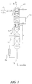
- FIG. 1 illustrates a process flow according to a first embodiment of the invention.
- the process begins with an exhaust gas mixture from a semiconductor processing tool, which may be any type of tool which uses or generates PFCs.
- the exhaust gas mixture containing PFCs, carrier gases and any other process gases, is removed from the processing tool through an exhaust line.
- the gas mixture Prior to being introduced into the gas purification system, the gas mixture is preferably passed through a filter, and then compressed in a compressor. The compressed gas mixture is then optionally routed to a cooler or a heater to provide a desired temperature for the compressed gas mixture.
- the gas mixture is next preferably introduced into a dry scrubber and/or a wet scrubber to remove silicon hydrides, e.g., NH 3 and AsH 3 , tetraethoxysilane (TEOS), halogens and halides.
- the exhaust stream can next be filtered to remove dust, particles, droplets, and the like, having sizes greater than, for example, 20 ⁇ m. Additionally, particles and dust may be removed in a filter upstream from the scrubber.
- the exhaust stream is preferably passed through one or more systems to recover a majority of the PFCs while rejecting a majority of the carrier gases.
- suitable PFC recovery units are described in copending application Serial No. , attorney docket no. Serie 4030-CIP, filed on even date herewith.
- the exhaust gas can be sent to a membrane unit through which the carrier gases of the mixture permeate, and are recovered or vented as a waste gas which can be purified and/or recycled according to known means.
- a concentrated PFC feed stream flows from the non-permeate side of the membrane unit.
- This concentrated PFC feed stream is then introduced into a purification system, which produces purified product streams and waste streams.
- the PFC feed stream can be introduced to the purification system directly from the semiconductor processing tool or the recovery unit, or from a gas storage medium such as a cylinder, a bulk storage tank, or a tube trailer.
- inventive method and system are not limited in any way by the existence of any specific type of upstream system. Nor are the method and system limited to the treatment of any specific PFCs or PFC mixture.
- a breakdown of the PFCs present in a typical PFC feed stream is as follows: C 2 F 6 61.0 mol% CF 4 30.0 mol% SF 6 2.0 mol% NF 3 1.5 mol% CHF 3 0.5 mol% N 2 5.0 mol%
- concentrated PFC feed stream 1 from the recovery unit is compressed to a pressure lower than about 30 bar, preferably in the range of from about 5 to 15 bar, and more preferably from about 7 to 12 bar, and is cooled to a temperature in the range of from about -120 to -30°C, preferably from about -30 to -60°C, by, for example, a heat exchanger 24.
- PFC feed stream 1 is then fed to one or more cold adsorption units 2 in which any existing impurities in the form of, for example, CHF 3 , C 2 F 4 , and NF 3 , are removed through cold adsorption.
- the non-adsorbed gas species in the effluent 3 from cold adsorption units 2 include, for example, SF 6 , C 2 F 6 , CF 4 and N 2 , and may include trace amounts of the aforementioned impurities, i.e., CHF 3 , C 2 F 4 , and NF 3 .
- Suitable cold adsorption units 2 are known in the art, and are described, for example, in Perry's Chemical Engineers' Handbook.
- Suitable sorbent materials include, but are not limited to, 13X, 10X, 5A, 4A, 3A, Dowrex, PCB, and other ion exchanged zeolite adsorbents.
- Adsorption unit effluent 3 is next fed to first cold distillation column 4, where effluent 3 is fractionated into light product 5 and heavy product 6.
- the C 2 F 6 , CF 4 and N 2 are removed in the light product 5, which ideally contains no more than 5 ppm of SF 6 .
- Substantially all of the SF 6 introduced into first distillation column 4 is removed in heavy product 6.
- Heavy product 6 also includes those components which are heavier (i.e., higher-boiling) than SF 6 and may include some lighter (i.e., lower-boiling) components.
- First column 4 operates at a pressure in the range of from about 5 to 15 bar, and a temperature in the range of from about 0 to -90°C, preferably from about -10 to -45°C. Control of the pressure and temperature inside distillation columns is commonly understood by those skilled in the art.
- the cooling duty for condenser 7 of first column 4 is provided by a refrigeration unit 8.
- the operational pressure of first column 4 is such that conventional refrigerants can be used in condenser 7. Suitable refrigerants are known to those skilled in the art, and include, for example, freons such as freon 22.
- the heat duty can be provided by a heat source 10, such as an electric heater, an ambient vaporizer, or a heating medium stream, for example, a water stream.
- a heat source 10 such as an electric heater, an ambient vaporizer, or a heating medium stream, for example, a water stream.
- Light product 5 from first distillation column 4 is fed to second distillation column 11, which is fractionated into heavy product 12 containing purified C 2 F 6 , and possibly containing impurities such as CHF 3 , and light product 13 which includes CF 4 and N 2 .
- Light product 13 may contain additional impurities, such as NF 3 .
- Second column 11 preferably operates at a pressure in the range of from about 5 to 12 bar and a temperature in the range of from about 0 to -120°C, and more preferably from about -25 to -100°C.
- Second column light product 13 is next fed to third distillation column 14, which is fractionated into a light product 15 and a heavy product 16.
- Light product 15 is N 2 gas, which may contain impurities, such as other air impurities.
- Purified CF 4 is removed as heavy product 16. This product may include impurities such as NF 3 .
- Third column 14 preferably operates at a pressure in the range of from about 1 to 10 bar and a temperature in the range of from about -50 to -200°C, more preferably from about -90 to -180°C.
- Second distillation column 11 is preferably thermally linked with third distillation column 14 by a common reboiler/condenser arrangement.
- This thermal linkage utilizes the heating and/or cooling capacity of one or more streams or stream portions from one distillation column to provide reboiling and/or condensing duties, respectively, to another column.
- the thermal linkage of columns 11 and 14 can be accomplished by physically stacking one column on top of the other column.
- the two columns can be contained in a single shell.
- condenser 17 of second column 11 is at least partially immersed in the liquid at the bottom of third column 14.
- the vapor at the top of second column 11 is conveyed into third column 14 through condenser 17 via line 18.
- This vapor provides reboiling duty to third column 14 for vaporizing at least a portion of the liquid in the bottom of third column 14.
- the thermal linkage can also be achieved by transporting, e.g., by pumping, either the liquid to be vaporized to the reboiler or the liquid reflux resulting from the condensation back to the column where the condensing vapor is originated.
- transporting e.g., by pumping, either the liquid to be vaporized to the reboiler or the liquid reflux resulting from the condensation back to the column where the condensing vapor is originated.
- columns 11 and 14 it is additionally or alternatively possible for columns 11 and 14 to be located adjacent to each other, rather than being stacked.
- condenser 17 can be located external to the column, and the heavy liquid from column 14 can be conveyed to condenser 17, where it is partially vaporized by the warmer vapor from the top of second column 11.
- the resulting condensed portion of this stream is conveyed using a pump or other suitable mechanism back to column 11 as reflux.
- the vapor portion is introduced into the third column as in the previously described embodiment.
- second column 11 and third column 14 are controlled such that there is ample temperature driving force for the colder CF 4 containing liquid in the bottom of third column 14 to condense the light vapor of second column 11. Consequently, the need for an external source of refrigeration for the second column condenser 17 can be eliminated.
- Liquid N 2 or another suitable cryogenic source 19 provides the refrigeration in the condenser 20 of third column 14, and is thus the only external source of refrigeration required by second and third columns 11 and 14 when such a thermally linked stacked column configuration is used.
- the liquid N 2 or suitable cryogen is vaporized in the process.
- the resulting cryogenic vapor stream 21 can be used to provide at least a portion of the cooling requirement in heat exchanger 22 for PFC feed stream 1.
- a liquid N 2 stream can also be injected as reflux liquid to the column thus economizing the reflux condenser.
- the means for providing the heat duty for the reboiler of second column 11 can be the same as those specified above with reference to the first column, e.g., heat sources, such as an electric heater, an ambient vaporizer, or a heating medium stream, for example, a water stream.
- heat sources such as an electric heater, an ambient vaporizer, or a heating medium stream, for example, a water stream.
- Second and third column heavy product streams 12 and 16 can each be fed into a separate storage tank 23 and 24, respectively.
- a portion of the product is vaporized in each of tanks 23 and 24 as purified C 2 F 6 and CF 4 vapor streams 25 and 26, respectively.
- At least portions of vapor streams 25 and 26 and first column heavy product 6, as well as any other product streams, can be recycled and combined with the PFC feed stream to control composition, and to dampen out any large fluctuations in the composition or flow of the feed. This pure product recycle is particularly advantageous to the process.
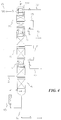
- the first, second and third distillation columns 4, 11 and 14 can be stacked on top of and thermally linked with each other, in a manner similar to that described above with reference to the two-column structure.
- the columns can alternatively be disposed adjacent to each other while being thermally linked, as described above.
- first column 4 is preferably disposed on the bottom and third column 14 on top. Given this arrangement, the process can be controlled such that the condenser 7 of first column 4 provides reboil duty to second column 11, and the condenser 17 of second column 11 provides reboil duty to third column 14.
- This embodiment is particularly advantageous, since the only required source of refrigeration is liquid N 2 , or some other suitable cryogenic source.
- a fourth distillation column can be provided to further purify heavy product 12, i.e., the C 2 F 6 product, from second distillation column 11.
- heavy product 12 i.e., the C 2 F 6 product
- use of a fourth distillation column allows for the removal of the remaining impurities, such as CHF 3 , from second column heavy stream 12.
- one or more cold adsorption units can be added to remove remaining impurities such as NF 3 from the CF 4 heavy product of third column 14.
- Advantages of this embodiment include eliminating the possibility of co-adsorption and subsequent loss of a desired product, e.g., C 2 F 6 , with the impurities.
- cold adsorption units 2 can be moved to a position immediately downstream of first distillation column 4. In this case, light product 5 from the first distillation column is introduced to the adsorption units 2, with the resulting effluent stream being fed to second distillation column 11.
- This configuration makes possible the elimination of the PFC-containing stream pre-cooling step prior to introduction into the first column.
- the cryogenic source may be used elsewhere.
- Further advantages associated with this embodiment include a decrease in adsorption unit size due to the removal of heavy components such as SF 6 in first column 4 prior to adsorption. Additionally or alternatively, the adsorption can be performed at colder temperatures due to the elimination of such heavy components, which freeze at warmer temperatures.
- the gas feed to the purification system can include recovered exhausts from multiple semiconductor processing tools and from multiple manufacturing sites, wide variations in feed gas composition are possible.
- an exceptional method for controlling the composition and flow rate of the feed stream is provided. This facilitates a stable and reliable operation of the purification system.
- At least portions of one or more of the product streams can be recycled directly to the semiconductor processing tool, or packaged in suitable fashion for recycle and reuse in such tools. Considerable savings can result since the volume of fresh materials which must be purchased can be significantly reduced.
Landscapes
- Chemical & Material Sciences (AREA)
- Organic Chemistry (AREA)
- Chemical Kinetics & Catalysis (AREA)
- Oil, Petroleum & Natural Gas (AREA)
- Engineering & Computer Science (AREA)
- Analytical Chemistry (AREA)
- General Chemical & Material Sciences (AREA)
- Thermal Sciences (AREA)
- Physics & Mathematics (AREA)
- Health & Medical Sciences (AREA)
- General Health & Medical Sciences (AREA)
- Inorganic Chemistry (AREA)
- Organic Low-Molecular-Weight Compounds And Preparation Thereof (AREA)
- Treating Waste Gases (AREA)
Applications Claiming Priority (2)
| Application Number | Priority Date | Filing Date | Title |
|---|---|---|---|
| US783446 | 1997-01-16 | ||
| US08/783,446 US5779863A (en) | 1997-01-16 | 1997-01-16 | Perfluorocompound separation and purification method and system |
Publications (2)
| Publication Number | Publication Date |
|---|---|
| EP0854335A2 true EP0854335A2 (fr) | 1998-07-22 |
| EP0854335A3 EP0854335A3 (fr) | 1998-12-30 |
Family
ID=25129273
Family Applications (1)
| Application Number | Title | Priority Date | Filing Date |
|---|---|---|---|
| EP98400067A Withdrawn EP0854335A3 (fr) | 1997-01-16 | 1998-01-15 | Procédé et dispositif pour la séparation et la purification de composés perfluorés |
Country Status (8)
| Country | Link |
|---|---|
| US (1) | US5779863A (fr) |
| EP (1) | EP0854335A3 (fr) |
| JP (1) | JP3284096B2 (fr) |
| KR (1) | KR19980070554A (fr) |
| CN (1) | CN1193620A (fr) |
| IL (1) | IL122946A (fr) |
| MY (1) | MY133563A (fr) |
| TW (1) | TW357104B (fr) |
Cited By (3)
| Publication number | Priority date | Publication date | Assignee | Title |
|---|---|---|---|---|
| EP1205232A3 (fr) * | 2000-11-10 | 2002-07-17 | Organo Corporation | Appareil de séparation de gaz et procédé pour séparer des gaz |
| EP2942324A4 (fr) * | 2013-06-17 | 2016-10-05 | Purification Equipment Res Inst Of Csic | Procédé de purification de fluorure de carbonyle |
| CN112891973A (zh) * | 2021-01-15 | 2021-06-04 | 中国科学院上海应用物理研究所 | 一种降低卤化物熔盐中氧含量的方法 |
Families Citing this family (25)
| Publication number | Priority date | Publication date | Assignee | Title |
|---|---|---|---|---|
| US5992175A (en) * | 1997-12-08 | 1999-11-30 | Ipsi Llc | Enhanced NGL recovery processes |
| US6257018B1 (en) * | 1999-06-28 | 2001-07-10 | Praxair Technology, Inc. | PFC recovery using condensation |
| US6468490B1 (en) * | 2000-06-29 | 2002-10-22 | Applied Materials, Inc. | Abatement of fluorine gas from effluent |
| US6689252B1 (en) | 1999-07-28 | 2004-02-10 | Applied Materials, Inc. | Abatement of hazardous gases in effluent |
| US6673323B1 (en) | 2000-03-24 | 2004-01-06 | Applied Materials, Inc. | Treatment of hazardous gases in effluent |
| US6391146B1 (en) | 2000-04-11 | 2002-05-21 | Applied Materials, Inc. | Erosion resistant gas energizer |
| US6457327B1 (en) | 2000-05-08 | 2002-10-01 | Air Products And Chemicals, Inc. | Process for concentrating fluorine compounds |
| US6276168B1 (en) | 2000-05-08 | 2001-08-21 | Air Products And Chemicals, Inc. | Purification of nitrogen trifluoride by continuous cryogenic distillation |
| WO2002000963A1 (fr) * | 2000-06-23 | 2002-01-03 | Steven John Ouderkirk | Depot par faisceau selectif |
| US6824748B2 (en) * | 2001-06-01 | 2004-11-30 | Applied Materials, Inc. | Heated catalytic treatment of an effluent gas from a substrate fabrication process |
| US6955707B2 (en) * | 2002-06-10 | 2005-10-18 | The Boc Group, Inc. | Method of recycling fluorine using an adsorption purification process |
| US7261779B2 (en) * | 2003-06-05 | 2007-08-28 | Lockheed Martin Corporation | System, method, and apparatus for continuous synthesis of single-walled carbon nanotubes |
| US20050011442A1 (en) * | 2003-06-24 | 2005-01-20 | International Business Machines Corporation | Plasma processing material reclamation and reuse |
| US7569193B2 (en) | 2003-12-19 | 2009-08-04 | Applied Materials, Inc. | Apparatus and method for controlled combustion of gaseous pollutants |
| US7736599B2 (en) | 2004-11-12 | 2010-06-15 | Applied Materials, Inc. | Reactor design to reduce particle deposition during process abatement |
| CN101300411B (zh) | 2005-10-31 | 2012-10-03 | 应用材料公司 | 制程减降反应器 |
| JP5202836B2 (ja) * | 2006-12-01 | 2013-06-05 | 日本エア・リキード株式会社 | キセノンの回収システムおよび回収装置 |
| CN101857202B (zh) * | 2010-06-04 | 2012-01-25 | 黎明化工研究院 | 一种六氟化硫的提纯方法及其设备 |
| CN102500338B (zh) * | 2011-11-23 | 2013-10-09 | 清华大学 | Pfoa吸附剂及其制备方法 |
| CN103170150B (zh) * | 2011-12-21 | 2016-01-06 | 株式会社吴羽 | 蒸馏塔系和使用该蒸馏塔系的1,1-二氯乙烯单体的蒸馏方法 |
| KR101859110B1 (ko) * | 2017-04-26 | 2018-06-29 | 한국생산기술연구원 | 과불화 화합물 저감 및 불화주석 생성 장치 및 방법 |
| KR102845376B1 (ko) * | 2022-03-08 | 2025-08-12 | 크라이오에이치앤아이(주) | 배기 가스 처리 장치 |
| KR20260037113A (ko) | 2023-07-14 | 2026-03-17 | 클라로스 테크놀로지스 인코포레이티드 | 수용액에서 요오드를 포획하는 방법 및 시스템 |
| US12545601B2 (en) | 2023-07-14 | 2026-02-10 | Claros Technologies Inc. | Methods and systems of photosensitizer recovery for improved PFAS destruction |
| US12534390B2 (en) | 2023-07-14 | 2026-01-27 | Claros Technologies Inc. | Methods and systems of nitrate removal in aqueous systems for improved PFAS destruction |
Family Cites Families (12)
| Publication number | Priority date | Publication date | Assignee | Title |
|---|---|---|---|---|
| JPS4842620B1 (fr) * | 1968-01-12 | 1973-12-13 | ||
| US4177196A (en) * | 1976-01-16 | 1979-12-04 | Interox Chemicals Limited | Epoxidation |
| DE3729106A1 (de) * | 1987-09-01 | 1989-03-09 | Hoechst Ag | Verfahren zur gewinnung von reinem tetrafluorethylen |
| WO1992019576A1 (fr) * | 1991-05-06 | 1992-11-12 | E.I. Du Pont De Nemours And Company | Procede d'elaboration du pentafluoroethane |
| ZA923274B (en) * | 1991-05-06 | 1993-11-08 | Du Pont | Process for the manufacture of pentafluoroethane |
| US5087329A (en) * | 1991-05-16 | 1992-02-11 | E. I. Du Pont De Nemours And Company | Process for separating pentafluoroethane from a mixture of halogenated hydrocarbons containing chloropentafluoroethane |
| ES2090668T3 (es) * | 1992-03-10 | 1996-10-16 | Du Pont | Purificacion de productos de hexafluoroetano. |
| US5421964A (en) * | 1993-04-30 | 1995-06-06 | E. I. Du Pont De Nemours And Company | Process for separating HCl and halocarbons |
| US5470442A (en) * | 1994-03-11 | 1995-11-28 | E. I. Du Pont De Nemours And Company | Separating and removing impurities from tetrafluoroethanes by using extractive distillation |
| US5502969A (en) * | 1995-02-16 | 1996-04-02 | Praxair Technology, Inc. | Cryogenic rectification system for fluorine compound recovery |
| US5639355A (en) * | 1995-03-13 | 1997-06-17 | Texaco Chemical Inc. | Method for enhancing the yield of tertiary butyl alcohol in a tertiary butyl alcohol recovery process |
| US5626033A (en) * | 1996-07-12 | 1997-05-06 | The Boc Group, Inc. | Process for the recovery of perfluorinated compounds |
-
1997
- 1997-01-16 US US08/783,446 patent/US5779863A/en not_active Expired - Fee Related
-
1998
- 1998-01-13 CN CN98104147A patent/CN1193620A/zh active Pending
- 1998-01-14 TW TW087100415A patent/TW357104B/zh active
- 1998-01-15 MY MYPI98000172A patent/MY133563A/en unknown
- 1998-01-15 EP EP98400067A patent/EP0854335A3/fr not_active Withdrawn
- 1998-01-15 IL IL12294698A patent/IL122946A/xx not_active IP Right Cessation
- 1998-01-16 JP JP00688298A patent/JP3284096B2/ja not_active Expired - Fee Related
- 1998-01-16 KR KR1019980001109A patent/KR19980070554A/ko not_active Withdrawn
Cited By (4)
| Publication number | Priority date | Publication date | Assignee | Title |
|---|---|---|---|---|
| EP1205232A3 (fr) * | 2000-11-10 | 2002-07-17 | Organo Corporation | Appareil de séparation de gaz et procédé pour séparer des gaz |
| US6702874B2 (en) | 2000-11-10 | 2004-03-09 | Organo Corporation | Gas separation apparatus and gas separation method |
| EP2942324A4 (fr) * | 2013-06-17 | 2016-10-05 | Purification Equipment Res Inst Of Csic | Procédé de purification de fluorure de carbonyle |
| CN112891973A (zh) * | 2021-01-15 | 2021-06-04 | 中国科学院上海应用物理研究所 | 一种降低卤化物熔盐中氧含量的方法 |
Also Published As
| Publication number | Publication date |
|---|---|
| CN1193620A (zh) | 1998-09-23 |
| IL122946A0 (en) | 1998-08-16 |
| TW357104B (en) | 1999-05-01 |
| JPH11171807A (ja) | 1999-06-29 |
| KR19980070554A (ko) | 1998-10-26 |
| US5779863A (en) | 1998-07-14 |
| IL122946A (en) | 2000-10-31 |
| MY133563A (en) | 2007-11-30 |
| EP0854335A3 (fr) | 1998-12-30 |
| JP3284096B2 (ja) | 2002-05-20 |
Similar Documents
| Publication | Publication Date | Title |
|---|---|---|
| US5779863A (en) | Perfluorocompound separation and purification method and system | |
| EP0754487B1 (fr) | Procédé et dispositif pour séparer et récupérer des composés perfluoriques gazeux | |
| US6605133B1 (en) | Process and system for separation and recovery of perfluorocompound gases | |
| US20030161780A1 (en) | Recycle for supercritical carbon dioxide | |
| US6063353A (en) | Process for krypton an xenon extraction | |
| US7794523B2 (en) | Method for the recovery and re-use of process gases | |
| CA1166145A (fr) | Methode d'extraction de l'azote du gaz naturel | |
| JP3238317B2 (ja) | 弗素化合物回収のための低温精留系 | |
| EP1065459A2 (fr) | Récupération de PFC par condensation | |
| EP1430262B1 (fr) | Procede et appareil de purification de bromure d'hydrogene | |
| CA2243832C (fr) | Systeme de rectification cryogenique pour la recuperation de composes fluores | |
| US20050118085A1 (en) | Chamber cleaning or etching gas regeneration and recycle method | |
| KR101955015B1 (ko) | 아산화질소 회수 방법 및 장치 | |
| JP4430351B2 (ja) | フッ素化合物ガスの分離精製装置 | |
| HK1014930A (en) | Perfluorocompound separation and purification method and system | |
| CA2345489C (fr) | Processus de concentration de composes du fluor | |
| JP3847106B2 (ja) | パーフルオロコンパウンドの低温精製によるリサイクル方法 | |
| EP1048337A1 (fr) | Récuperation des composés perfluorés présents dans les gaz d'échappement de procédés de fabrication de semi-conducteurs avec recyclage du diluant de la pompe à vide | |
| KR20240178653A (ko) | 반도체 공정에서 배출된 폐가스를 포집, 정제하여 안전하고 경제적으로 고순도 헬륨과 질소 가스를 생산하는 방법 | |
| MXPA00006385A (en) | Recovery of pfc using condensation |
Legal Events
| Date | Code | Title | Description |
|---|---|---|---|
| PUAI | Public reference made under article 153(3) epc to a published international application that has entered the european phase |
Free format text: ORIGINAL CODE: 0009012 |
|
| AK | Designated contracting states |
Kind code of ref document: A2 Designated state(s): BE DE FR GB IE IT NL |
|
| AX | Request for extension of the european patent |
Free format text: AL;LT;LV;MK;RO;SI |
|
| PUAL | Search report despatched |
Free format text: ORIGINAL CODE: 0009013 |
|
| AK | Designated contracting states |
Kind code of ref document: A3 Designated state(s): AT BE CH DE DK ES FI FR GB GR IE IT LI LU MC NL PT SE |
|
| AX | Request for extension of the european patent |
Free format text: AL;LT;LV;MK;RO;SI |
|
| 17P | Request for examination filed |
Effective date: 19990630 |
|
| AKX | Designation fees paid |
Free format text: BE DE FR GB IE IT NL |
|
| 17Q | First examination report despatched |
Effective date: 20000912 |
|
| STAA | Information on the status of an ep patent application or granted ep patent |
Free format text: STATUS: THE APPLICATION HAS BEEN WITHDRAWN |
|
| 18W | Application withdrawn |
Withdrawal date: 20020713 |