EP0854347B1 - Méthode de fabrication de sections de radiateurs - Google Patents
Méthode de fabrication de sections de radiateurs Download PDFInfo
- Publication number
- EP0854347B1 EP0854347B1 EP98830019A EP98830019A EP0854347B1 EP 0854347 B1 EP0854347 B1 EP 0854347B1 EP 98830019 A EP98830019 A EP 98830019A EP 98830019 A EP98830019 A EP 98830019A EP 0854347 B1 EP0854347 B1 EP 0854347B1
- Authority
- EP
- European Patent Office
- Prior art keywords
- radiant
- channels
- heads
- cavity
- tubular
- Prior art date
- Legal status (The legal status is an assumption and is not a legal conclusion. Google has not performed a legal analysis and makes no representation as to the accuracy of the status listed.)
- Expired - Lifetime
Links
- 238000004519 manufacturing process Methods 0.000 title claims description 6
- 238000000034 method Methods 0.000 claims description 13
- 230000008878 coupling Effects 0.000 claims description 9
- 238000010168 coupling process Methods 0.000 claims description 9
- 238000005859 coupling reaction Methods 0.000 claims description 9
- 238000004512 die casting Methods 0.000 claims description 5
- 238000003466 welding Methods 0.000 claims description 3
- 238000004891 communication Methods 0.000 claims description 2
- 230000000295 complement effect Effects 0.000 claims description 2
- 230000002093 peripheral effect Effects 0.000 claims description 2
- 238000005304 joining Methods 0.000 claims 2
- 238000004026 adhesive bonding Methods 0.000 description 3
- 238000004140 cleaning Methods 0.000 description 3
- 239000000463 material Substances 0.000 description 3
- 238000010438 heat treatment Methods 0.000 description 2
- 239000011796 hollow space material Substances 0.000 description 2
- XAGFODPZIPBFFR-UHFFFAOYSA-N aluminium Chemical compound [Al] XAGFODPZIPBFFR-UHFFFAOYSA-N 0.000 description 1
- 229910052782 aluminium Inorganic materials 0.000 description 1
- 239000004411 aluminium Substances 0.000 description 1
- 239000002131 composite material Substances 0.000 description 1
- 238000009792 diffusion process Methods 0.000 description 1
- 238000001125 extrusion Methods 0.000 description 1
- 239000003292 glue Substances 0.000 description 1
- 238000009499 grossing Methods 0.000 description 1
- 238000003754 machining Methods 0.000 description 1
- 238000007789 sealing Methods 0.000 description 1
Images

Classifications
-
- F—MECHANICAL ENGINEERING; LIGHTING; HEATING; WEAPONS; BLASTING
- F28—HEAT EXCHANGE IN GENERAL
- F28F—DETAILS OF HEAT-EXCHANGE AND HEAT-TRANSFER APPARATUS, OF GENERAL APPLICATION
- F28F21/00—Constructions of heat-exchange apparatus characterised by the selection of particular materials
- F28F21/08—Constructions of heat-exchange apparatus characterised by the selection of particular materials of metal
- F28F21/088—Constructions of heat-exchange apparatus characterised by the selection of particular materials of metal for domestic or space-heating systems
-
- F—MECHANICAL ENGINEERING; LIGHTING; HEATING; WEAPONS; BLASTING
- F28—HEAT EXCHANGE IN GENERAL
- F28D—HEAT-EXCHANGE APPARATUS, NOT PROVIDED FOR IN ANOTHER SUBCLASS, IN WHICH THE HEAT-EXCHANGE MEDIA DO NOT COME INTO DIRECT CONTACT
- F28D1/00—Heat-exchange apparatus having stationary conduit assemblies for one heat-exchange medium only, the media being in contact with different sides of the conduit wall, in which the other heat-exchange medium is a large body of fluid, e.g. domestic or motor car radiators
- F28D1/02—Heat-exchange apparatus having stationary conduit assemblies for one heat-exchange medium only, the media being in contact with different sides of the conduit wall, in which the other heat-exchange medium is a large body of fluid, e.g. domestic or motor car radiators with heat-exchange conduits immersed in the body of fluid
- F28D1/04—Heat-exchange apparatus having stationary conduit assemblies for one heat-exchange medium only, the media being in contact with different sides of the conduit wall, in which the other heat-exchange medium is a large body of fluid, e.g. domestic or motor car radiators with heat-exchange conduits immersed in the body of fluid with tubular conduits
- F28D1/053—Heat-exchange apparatus having stationary conduit assemblies for one heat-exchange medium only, the media being in contact with different sides of the conduit wall, in which the other heat-exchange medium is a large body of fluid, e.g. domestic or motor car radiators with heat-exchange conduits immersed in the body of fluid with tubular conduits the conduits being straight
- F28D1/05308—Assemblies of conduits connected side by side or with individual headers, e.g. section type radiators
-
- F—MECHANICAL ENGINEERING; LIGHTING; HEATING; WEAPONS; BLASTING
- F28—HEAT EXCHANGE IN GENERAL
- F28F—DETAILS OF HEAT-EXCHANGE AND HEAT-TRANSFER APPARATUS, OF GENERAL APPLICATION
- F28F9/00—Casings; Header boxes; Auxiliary supports for elements; Auxiliary members within casings
- F28F9/02—Header boxes; End plates
-
- F—MECHANICAL ENGINEERING; LIGHTING; HEATING; WEAPONS; BLASTING
- F28—HEAT EXCHANGE IN GENERAL
- F28F—DETAILS OF HEAT-EXCHANGE AND HEAT-TRANSFER APPARATUS, OF GENERAL APPLICATION
- F28F9/00—Casings; Header boxes; Auxiliary supports for elements; Auxiliary members within casings
- F28F9/02—Header boxes; End plates
- F28F9/04—Arrangements for sealing elements into header boxes or end plates
- F28F9/16—Arrangements for sealing elements into header boxes or end plates by permanent joints, e.g. by rolling
- F28F9/162—Arrangements for sealing elements into header boxes or end plates by permanent joints, e.g. by rolling by using bonding or sealing substances, e.g. adhesives
-
- F—MECHANICAL ENGINEERING; LIGHTING; HEATING; WEAPONS; BLASTING
- F28—HEAT EXCHANGE IN GENERAL
- F28F—DETAILS OF HEAT-EXCHANGE AND HEAT-TRANSFER APPARATUS, OF GENERAL APPLICATION
- F28F9/00—Casings; Header boxes; Auxiliary supports for elements; Auxiliary members within casings
- F28F9/02—Header boxes; End plates
- F28F9/04—Arrangements for sealing elements into header boxes or end plates
- F28F9/16—Arrangements for sealing elements into header boxes or end plates by permanent joints, e.g. by rolling
- F28F9/165—Arrangements for sealing elements into header boxes or end plates by permanent joints, e.g. by rolling by using additional preformed parts, e.g. sleeves, gaskets
-
- F—MECHANICAL ENGINEERING; LIGHTING; HEATING; WEAPONS; BLASTING
- F28—HEAT EXCHANGE IN GENERAL
- F28F—DETAILS OF HEAT-EXCHANGE AND HEAT-TRANSFER APPARATUS, OF GENERAL APPLICATION
- F28F9/00—Casings; Header boxes; Auxiliary supports for elements; Auxiliary members within casings
- F28F9/26—Arrangements for connecting different sections of heat-exchange elements, e.g. of radiators
- F28F9/262—Arrangements for connecting different sections of heat-exchange elements, e.g. of radiators for radiators
-
- F—MECHANICAL ENGINEERING; LIGHTING; HEATING; WEAPONS; BLASTING
- F28—HEAT EXCHANGE IN GENERAL
- F28D—HEAT-EXCHANGE APPARATUS, NOT PROVIDED FOR IN ANOTHER SUBCLASS, IN WHICH THE HEAT-EXCHANGE MEDIA DO NOT COME INTO DIRECT CONTACT
- F28D21/00—Heat-exchange apparatus not covered by any of the groups F28D1/00 - F28D20/00
- F28D2021/0019—Other heat exchangers for particular applications; Heat exchange systems not otherwise provided for
- F28D2021/0035—Other heat exchangers for particular applications; Heat exchange systems not otherwise provided for for domestic or space heating, e.g. heating radiators
Definitions
- the present invention relates to a method of producing thermal radiators according to the preamble of claim 1. Such a method is known for instance from FR-A-1 201 614.
- Thermal equipment industry in particular for domestic heating, uses radiators formed by tubular radiant elements arranged vertically and equipped at their ends with relative heads that define suitable reciprocal connection means; the heads are connected one to another by e.g. threaded couplings, provided with suitable sealing means.
- the above mentioned radiant groups are entirely obtained by die-casting or otherwise made of a pair of heads obtained by die-casting, to which a tubular element is connected; in some cases the tubular element is suitably finned so as to improve heat diffusion.
- the radiant groups obtained in this way are usually expensive.
- Document FR-A-1.201.614 relates to a composite element for thermal radiators.
- a head element is provided, by which four pipes are connected to each other at their ends.
- the head element is made by die casting a fusible material, leaving an hollow space therein.
- the hollow space inside the head element is obtained by inserting a core that is broken in small pieces, after the head element has cooled, to take it out therefrom.
- the inside of the head element is therefore not well clean, smooth and perfectly formed. Pieces of the core can remain inside the head element, thus provoking problems during operation or requiring further cleaning operation. Smoothing, finishing and cleaning must be performed while working inside the hollow of the head element, which is rather complicated.
- Document FR-A-1.425.677 discloses a tubular radiator in which vertical pipes are connected to head elements by means of gluing.
- the object of the present invention is to provide a method which allows to obtain cheap end heads for radiant groups of thermal radiators.
- Another object of the present invention is to provide a method for producing safe to use and highly efficient end heads for thermal radiators in simple and economical way.
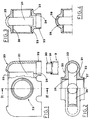
- the subject method includes first, die-casting of the bodies 20 of a pair of end heads 2 of a radiant group 1. These heads are preferably made of aluminium.
- Each body 20 has a flattened form, with outer corners suitably rounded, and has a cavity 21 extending on a median plane from its top narrow surface.
- An opening 25 extends along the top surface of the body 20, so that the cavity is open to the outside. The edges of the opening 25 are bevelled.
- the channels 22 have circular section and limited axial extension. Moreover, on their inner surface, the channels 22 feature respective shoulders 24.
- the cavity 21 communicates also with a pair of pipe stubs 23, extending from opposite sides of the body 20.
- the axis of each pipe stub is perpendicular to the median pane of the body.
- the inner surface of the pipe stubs 23 is threaded, so as to form threaded sections 26, so that respective couplings 4 can be screwed thereto for connecting two or more adjacent radiant groups 1.
- the cavity 21 of the body 20 is closed on the side opposite to the channels 22 by a shaped plate 28, whose form is complementary to the opening 25; the closing plate 28 is firmly joined to the body 20 by a peripheral welding 29 (Fig. 4).
- the closing plate 28 has preferably a rounded profile, so as to reconstruct the continuity of the outer surface of said head 2.
- the so made heads 2 are firmly joined by the channels 22 to the opposite ends of a corresponding plurality of tubular radiant elements 3, arranged coaxial to the same channels 22 (Fig. 5).
- the tubular elements 3 are preferably obtained by extrusion.
- the tubular radiant elements 3 are aimed at being tightly introduced inside the channels 22 and, at their ends, these elements 3 are provided with respective tapered mouths 30, which engage with the narrow part of these channels 22 defined by the relative shoulders 24.
- Respective gaskets 31 are mounted on the mouths 30 for keeping them tight against the above mentioned shoulders 24.
- the tubular radiant elements 3 are firmly joined to the heads 2 by suitable glues, spread on the coupling housings defined by the channels 22 of the heads 2.
- the so obtained radiant group 1 is put in a vice equipped with a centring device 10 which precisely determines the distance between the centres of said threaded pipe stubs 23 of the heads 2 (Fig. 6).
- the device 10 is substantially formed by a frame 11 equipped, on its ends, with a pair of pegs 12, protruding transversally and aimed at engaging said pipe stubs 23 of the heads 2 of the radiant group 1.
- the distance between the pegs 12 is adjustable.
- the device 10 supports respective vices 13 which clamp the above mentioned heads 2 of the radiant group 1.
- the radiant group 1 is mounted on the device 10 by introducing the pegs 12, whose distance is precisely determined, into the pipe stubs 23 of the heads 2 and then by tightening these heads 2 between the vices 13 (Fig. 7).
- the radiant group 1 is kept in the vice for a period of time sufficient for completing the step of gluing the tubular elements 3 to the heads 2.
- the couplings 4 feature, in known way, sections threaded in opposite directions, separated by the above mentioned seal 5.
- the couplings 4 are preferably obtained from a metallic sheet, as disclosed in the Patent Application No. BO95A 000175, filed by the same Applicant.
- the subject method allows to obtain, in a simple way, radiant groups for heat radiators, formed by a pair of end die-cast heads and a plurality of tubular radiant elements.
- the above mentioned radiant groups support three tubular elements between the heads.
- tubular elements arranged in line can be provided, the number of which depends on requirements.
- tubular elements can be arranged not only in one line, but also in two or more lines, by providing the end heads with a corresponding number of channels connecting with these tubular elements.
- the length of the tubular elements can vary in relation to use specifications.
- the last feature results in advantageous lightness of the radiant groups, which facilitates their transport and assembling.
- the claimed invention provides for an opening made in the top wall of the end head.
- the opening left in the top wall permits to obtain the inside hollow by means of a rigid core, which is made from hard material.
- the rigid core can be very smooth and is each time surely fully removed. Therefore, the head thus obtained do not need any operation in the inside, neither cleaning nor finishing.
- the position of the opening, the top wall makes it possible to place therein a plate, e.g. with slanting edges, and to weld it very easily. Then a finishing operation is required, e.g. machining, to smooth the region of the welding, but these operation are carried out on the outside of the head, therefore very easily and quickly. Moreover, the result of the further operation is readily apparent without any need of special devices do get sight of the inside of the head. There is also no risk of leaving a part of the core inside the head.
Landscapes
- Engineering & Computer Science (AREA)
- Physics & Mathematics (AREA)
- Thermal Sciences (AREA)
- Mechanical Engineering (AREA)
- General Engineering & Computer Science (AREA)
- Gas Burners (AREA)
- Combustion Of Fluid Fuel (AREA)
- Heat-Exchange Devices With Radiators And Conduit Assemblies (AREA)
- Lining Or Joining Of Plastics Or The Like (AREA)
- Control Of Heat Treatment Processes (AREA)
Claims (3)
- Procédé de fabrication de têtes terminales pour sections radiantes de radiateurs thermiques, le procédé comprenant les étapes consistant à :couler sous pression les corps (20) d'une paire de têtes terminales (2) d'une section radiante (1), chacun desdits corps (20) comportant une cavité (21) et plusieurs canaux parallèles (22) formés à l'intérieur de celle-ci et positionnés de manière à communiquer entre eux par l'intermédiaire de ladite cavité, et une paire de bouts (23) de tuyaux, dans le prolongement des côtés opposés dudit corps (20), s'ouvrant dans ladite cavité ;fileter lesdits bouts (23) de tuyaux de sorte que des raccords (4) respectifs puissent y être vissés afin de raccorder les sections radiantes (1) adjacentes ;raccorder solidement les bouches coniques (30) des éléments radiants tubulaires (3) respectifs auxdits canaux (22) des têtes (2), de sorte que lesdits éléments tubulaires sont disposés coaxialement par rapport aux canaux (22) ;le procédé étant caractérisé en ce que ladite cavité (21) dudit corps (20) comporte une ouverture (25) dans la région de la surface supérieure de ce dernier, cette ouverture étant ensuite fermée par une plaque façonnée (28) dont la forme est complémentaire de ladite ouverture (25) de ladite cavité (21), ladite plaque de fermeture (28) étant raccordée solidement audit corps (20) par une soudure périphérique (29), ce qui permet de reconstruire la continuité de la surface extérieure de ladite tête (2).
- Procédé selon la revendication 1, caractérisé en ce que lesdits éléments radiants tubulaires (3) respectifs sont raccordés auxdits canaux (22) desdites têtes (2) en étant collés aux logements d'accouplement que définissent ces canaux (22), lesdits logements comportant des parties épaulées (24) relatives qui définissent des portions rétrécies correspondantes desdits canaux (22) avec lesquelles lesdites bouches coniques (30) desdits éléments tubulaires (3) s'accouplent.
- Procédé selon la revendication 1, caractérisé en ce que, pendant le raccordement desdits éléments radiants tubulaires (3) auxdits canaux (22), la section radiante (1) est placée dans un étau sur un dispositif de centrage (10) qui maintient la distance entre les centres desdits bouts (23) de tuyaux filetés desdites têtes terminales (2), ledit dispositif (10) étant équipé en ses extrémités d'une paire de chevilles (12), transversalement en saillie et à distance réglable, destinées à s'engager dans lesdits bouts (23) de tuyaux.
Applications Claiming Priority (2)
| Application Number | Priority Date | Filing Date | Title |
|---|---|---|---|
| ITBO970023 | 1997-01-20 | ||
| IT97BO000023A IT1290645B1 (it) | 1997-01-20 | 1997-01-20 | Metodo per la realizzazione di gruppi radianti per radiatori termici. |
Publications (3)
| Publication Number | Publication Date |
|---|---|
| EP0854347A2 EP0854347A2 (fr) | 1998-07-22 |
| EP0854347A3 EP0854347A3 (fr) | 1999-06-09 |
| EP0854347B1 true EP0854347B1 (fr) | 2002-05-15 |
Family
ID=11341861
Family Applications (1)
| Application Number | Title | Priority Date | Filing Date |
|---|---|---|---|
| EP98830019A Expired - Lifetime EP0854347B1 (fr) | 1997-01-20 | 1998-01-20 | Méthode de fabrication de sections de radiateurs |
Country Status (4)
| Country | Link |
|---|---|
| EP (1) | EP0854347B1 (fr) |
| DE (1) | DE69805336T2 (fr) |
| ES (1) | ES2175648T3 (fr) |
| IT (1) | IT1290645B1 (fr) |
Cited By (1)
| Publication number | Priority date | Publication date | Assignee | Title |
|---|---|---|---|---|
| EP4471364A1 (fr) * | 2023-05-30 | 2024-12-04 | Toussaint Cumbo | Radiateur modulable hybride |
Families Citing this family (10)
| Publication number | Priority date | Publication date | Assignee | Title |
|---|---|---|---|---|
| EP1070930A1 (fr) * | 1999-07-17 | 2001-01-24 | Zehnder Verkaufs- und Verwaltungs AG | Procédé de fabrication de radiateurs tubulaires |
| ITBO20010375A1 (it) * | 2001-06-13 | 2002-12-13 | Valter Lolli | Metodo per la realizzazione di elementi di testa per radiatori termici, ed elemento di testa realizzato con tale metodo |
| EP1995546A1 (fr) * | 2007-05-25 | 2008-11-26 | Irsap Spa | Procédé de fabrication d'un Radiateur et Radiateur |
| ITMI20081168A1 (it) * | 2008-06-26 | 2009-12-27 | Fondital Spa | Elemento di radiatore da riscaldamento a protezione totale anti-corrosione, e metodo di trattamento anti-corrosione di elementi di radiatori da riscaldamento |
| EA019174B1 (ru) * | 2009-05-12 | 2014-01-30 | Стилиак С.П.А. | Подводящий или отводящий коллектор отопительных трубчатых радиаторов и способ его изготовления |
| ITMI20131806A1 (it) * | 2013-10-30 | 2015-05-01 | Fondital Spa | Radiatore tubiero da riscaldamento e metodo per fabbricare un radiatore tubiero da riscaldamento |
| EP3062051A1 (fr) * | 2015-02-24 | 2016-08-31 | W-A Progettazioni S.r.l. | Module pour fabriquer des corps à rayonnement, corps luminescent obtenu et procédé de fabrication de ce module |
| ITUA20163619A1 (it) | 2016-05-19 | 2017-11-19 | W A Progettazioni S R L | Corpo radiante e metodo per la realizzazione dello stesso corpo radiante. |
| IT201900002883A1 (it) | 2019-02-28 | 2020-08-28 | W A Progettazioni S R L | Testata per radiatori termici e metodo per realizzare tale testata. |
| TR202013063A2 (tr) * | 2020-08-19 | 2020-10-21 | Roezmas Metal San Ve Tic A S | Radyatör ara bağlanti aparati ve ara bağlanti aparati üreti̇m yöntemi̇ |
Family Cites Families (6)
| Publication number | Priority date | Publication date | Assignee | Title |
|---|---|---|---|---|
| FR801452A (fr) * | 1936-01-31 | 1936-08-05 | Electricite Et Electromecaniqu | Corps échangeur de chaleur |
| FR1201614A (fr) * | 1958-07-05 | 1960-01-04 | éléments composites de radiateurs de chauffage central | |
| FR1425677A (fr) * | 1965-02-16 | 1966-01-24 | Buderus Eisenwerk | Radiateur tubulaire |
| DE2157266A1 (de) * | 1970-11-24 | 1972-05-31 | Societa accomandita semplice FARAL di Mariani & C, Campogalliano, Modena (Italien) | Heizkörperelement |
| FR2119405A5 (fr) * | 1971-12-07 | 1972-08-04 | Unicum Sa | |
| IT977937B (it) * | 1973-03-01 | 1974-09-20 | Davico Livio | Radiatori per impianti di riscaldamento |
-
1997
- 1997-01-20 IT IT97BO000023A patent/IT1290645B1/it active IP Right Grant
-
1998
- 1998-01-20 EP EP98830019A patent/EP0854347B1/fr not_active Expired - Lifetime
- 1998-01-20 DE DE69805336T patent/DE69805336T2/de not_active Expired - Fee Related
- 1998-01-20 ES ES98830019T patent/ES2175648T3/es not_active Expired - Lifetime
Cited By (1)
| Publication number | Priority date | Publication date | Assignee | Title |
|---|---|---|---|---|
| EP4471364A1 (fr) * | 2023-05-30 | 2024-12-04 | Toussaint Cumbo | Radiateur modulable hybride |
Also Published As
| Publication number | Publication date |
|---|---|
| EP0854347A3 (fr) | 1999-06-09 |
| ES2175648T3 (es) | 2002-11-16 |
| ITBO970023A1 (it) | 1998-07-20 |
| DE69805336T2 (de) | 2002-11-28 |
| IT1290645B1 (it) | 1998-12-10 |
| EP0854347A2 (fr) | 1998-07-22 |
| ITBO970023A0 (it) | 1997-01-20 |
| DE69805336D1 (de) | 2002-06-20 |
Similar Documents
| Publication | Publication Date | Title |
|---|---|---|
| EP0854347B1 (fr) | Méthode de fabrication de sections de radiateurs | |
| US6155339A (en) | Obround header for a heat exchanger | |
| EP0779489B1 (fr) | Echangeur de chaleur et plaque collectrice pour échangeur de chaleur | |
| US4856581A (en) | Heat exchanger unit formed of a plurality of modular units including connection couplers | |
| US5579832A (en) | Heat exchanger tube, apparatus for forming such a tube, and a heat exchanger comprising such tubes | |
| CA2308581C (fr) | Procede d'assemblage d'un echangeur de chaleur | |
| EP0514248B1 (fr) | Echangeur de chaleur muni d'une boîte à fluide tubulaire à cloisons transversales, et procédé pour sa réalisation | |
| JPS62200194A (ja) | 熱交換器用マニホルド及びその製造方法 | |
| CA2451363C (fr) | Methode de fabrication d'un element frontal pour appareils de chauffage, et element resultant | |
| JPH11230442A (ja) | モジュールパイプ接続システム | |
| DE60006075T2 (de) | Verbesserte kupplung für zwei rohre | |
| CA2272421A1 (fr) | Tube d'echangeur de chaleur et son procede de fabrication | |
| CN110323038A (zh) | 一种油浸电力变压器用铝合金散热器及制造方法 | |
| CN104551581A (zh) | 一种多重复合散热器的制备工艺 | |
| CA1314538C (fr) | Echangeur de chaleur en aluminium | |
| US20060137855A1 (en) | Brazed in place heat exchanger core window and method of making same | |
| FR2567247A1 (fr) | Procede de montage a etancheite de l'extremite d'un tube dans un trou d'une paroi, et echangeur de chaleur a faisceau de tubes realise par execution de ce procede | |
| FR2726076A1 (fr) | Echangeur de chaleur a boites collectrices tubulaires | |
| JP3632871B2 (ja) | ヘッダタンクの製造方法 | |
| ITTO960877A1 (it) | Radiatore componibile | |
| EP1918669B1 (fr) | Procédé de fabrication d'un élément d'une boîte collectrice d'un radiateur et élément de la boîte collectrice | |
| GB2094925A (en) | Spigot and socket connection for rail fencing | |
| JPS6222793Y2 (fr) | ||
| US5956847A (en) | Method for manufacturing a fluid coupling apparatus | |
| CN2711671Y (zh) | 双水道铜铝复合柱翼型散热器 |
Legal Events
| Date | Code | Title | Description |
|---|---|---|---|
| PUAI | Public reference made under article 153(3) epc to a published international application that has entered the european phase |
Free format text: ORIGINAL CODE: 0009012 |
|
| AK | Designated contracting states |
Kind code of ref document: A2 Designated state(s): DE ES FR |
|
| AX | Request for extension of the european patent |
Free format text: AL;LT;LV;MK;RO;SI |
|
| PUAL | Search report despatched |
Free format text: ORIGINAL CODE: 0009013 |
|
| AK | Designated contracting states |
Kind code of ref document: A3 Designated state(s): AT BE CH DE DK ES FI FR GB GR IE IT LI LU MC NL PT SE |
|
| AX | Request for extension of the european patent |
Free format text: AL;LT;LV;MK;RO;SI |
|
| 17P | Request for examination filed |
Effective date: 19991130 |
|
| AKX | Designation fees paid |
Free format text: DE ES FR |
|
| 17Q | First examination report despatched |
Effective date: 20010215 |
|
| GRAG | Despatch of communication of intention to grant |
Free format text: ORIGINAL CODE: EPIDOS AGRA |
|
| GRAG | Despatch of communication of intention to grant |
Free format text: ORIGINAL CODE: EPIDOS AGRA |
|
| GRAH | Despatch of communication of intention to grant a patent |
Free format text: ORIGINAL CODE: EPIDOS IGRA |
|
| GRAH | Despatch of communication of intention to grant a patent |
Free format text: ORIGINAL CODE: EPIDOS IGRA |
|
| GRAA | (expected) grant |
Free format text: ORIGINAL CODE: 0009210 |
|
| AK | Designated contracting states |
Kind code of ref document: B1 Designated state(s): DE ES FR |
|
| REF | Corresponds to: |
Ref document number: 69805336 Country of ref document: DE Date of ref document: 20020620 |
|
| ET | Fr: translation filed | ||
| REG | Reference to a national code |
Ref country code: ES Ref legal event code: FG2A Ref document number: 2175648 Country of ref document: ES Kind code of ref document: T3 |
|
| PLBE | No opposition filed within time limit |
Free format text: ORIGINAL CODE: 0009261 |
|
| STAA | Information on the status of an ep patent application or granted ep patent |
Free format text: STATUS: NO OPPOSITION FILED WITHIN TIME LIMIT |
|
| 26N | No opposition filed |
Effective date: 20030218 |
|
| PGFP | Annual fee paid to national office [announced via postgrant information from national office to epo] |
Ref country code: DE Payment date: 20031128 Year of fee payment: 7 |
|
| PGFP | Annual fee paid to national office [announced via postgrant information from national office to epo] |
Ref country code: ES Payment date: 20040107 Year of fee payment: 7 |
|
| PGFP | Annual fee paid to national office [announced via postgrant information from national office to epo] |
Ref country code: FR Payment date: 20040121 Year of fee payment: 7 |
|
| PG25 | Lapsed in a contracting state [announced via postgrant information from national office to epo] |
Ref country code: ES Free format text: LAPSE BECAUSE OF NON-PAYMENT OF DUE FEES Effective date: 20050121 |
|
| PG25 | Lapsed in a contracting state [announced via postgrant information from national office to epo] |
Ref country code: DE Free format text: LAPSE BECAUSE OF NON-PAYMENT OF DUE FEES Effective date: 20050802 |
|
| PG25 | Lapsed in a contracting state [announced via postgrant information from national office to epo] |
Ref country code: FR Free format text: LAPSE BECAUSE OF NON-PAYMENT OF DUE FEES Effective date: 20050930 |
|
| REG | Reference to a national code |
Ref country code: FR Ref legal event code: ST |
|
| REG | Reference to a national code |
Ref country code: ES Ref legal event code: FD2A Effective date: 20050121 |