EP0854560A1 - Concept d'évacuation de chaleur pour entranement électrique - Google Patents
Concept d'évacuation de chaleur pour entranement électrique Download PDFInfo
- Publication number
- EP0854560A1 EP0854560A1 EP98100161A EP98100161A EP0854560A1 EP 0854560 A1 EP0854560 A1 EP 0854560A1 EP 98100161 A EP98100161 A EP 98100161A EP 98100161 A EP98100161 A EP 98100161A EP 0854560 A1 EP0854560 A1 EP 0854560A1
- Authority
- EP
- European Patent Office
- Prior art keywords
- drive system
- motor
- housing
- fan
- ext
- Prior art date
- Legal status (The legal status is an assumption and is not a legal conclusion. Google has not performed a legal analysis and makes no representation as to the accuracy of the status listed.)
- Withdrawn
Links
- 230000017525 heat dissipation Effects 0.000 title description 5
- 238000001816 cooling Methods 0.000 claims abstract description 37
- 238000009423 ventilation Methods 0.000 claims description 20
- 230000008878 coupling Effects 0.000 claims description 6
- 238000010168 coupling process Methods 0.000 claims description 6
- 238000005859 coupling reaction Methods 0.000 claims description 6
- 239000003795 chemical substances by application Substances 0.000 description 20
- 238000010586 diagram Methods 0.000 description 2
- 239000011810 insulating material Substances 0.000 description 2
- 238000010276 construction Methods 0.000 description 1
- 239000002826 coolant Substances 0.000 description 1
- 238000001514 detection method Methods 0.000 description 1
- 239000000835 fiber Substances 0.000 description 1
- 238000009413 insulation Methods 0.000 description 1
- 230000010354 integration Effects 0.000 description 1
- 238000000034 method Methods 0.000 description 1
- 238000011084 recovery Methods 0.000 description 1
- 230000001360 synchronised effect Effects 0.000 description 1
Images

Classifications
-
- H—ELECTRICITY
- H02—GENERATION; CONVERSION OR DISTRIBUTION OF ELECTRIC POWER
- H02K—DYNAMO-ELECTRIC MACHINES
- H02K5/00—Casings; Enclosures; Supports
- H02K5/04—Casings or enclosures characterised by the shape, form or construction thereof
- H02K5/18—Casings or enclosures characterised by the shape, form or construction thereof with ribs or fins for improving heat transfer
-
- H—ELECTRICITY
- H02—GENERATION; CONVERSION OR DISTRIBUTION OF ELECTRIC POWER
- H02K—DYNAMO-ELECTRIC MACHINES
- H02K11/00—Structural association of dynamo-electric machines with electric components or with devices for shielding, monitoring or protection
- H02K11/30—Structural association with control circuits or drive circuits
- H02K11/33—Drive circuits, e.g. power electronics
-
- H—ELECTRICITY
- H02—GENERATION; CONVERSION OR DISTRIBUTION OF ELECTRIC POWER
- H02K—DYNAMO-ELECTRIC MACHINES
- H02K9/00—Arrangements for cooling or ventilating
- H02K9/14—Arrangements for cooling or ventilating wherein gaseous cooling medium circulates between the machine casing and a surrounding mantle
-
- H—ELECTRICITY
- H02—GENERATION; CONVERSION OR DISTRIBUTION OF ELECTRIC POWER
- H02K—DYNAMO-ELECTRIC MACHINES
- H02K5/00—Casings; Enclosures; Supports
- H02K5/04—Casings or enclosures characterised by the shape, form or construction thereof
- H02K5/20—Casings or enclosures characterised by the shape, form or construction thereof with channels or ducts for flow of cooling medium
- H02K5/207—Casings or enclosures characterised by the shape, form or construction thereof with channels or ducts for flow of cooling medium with openings in the casing specially adapted for ambient air
Definitions
- the invention relates to an electric drive system with motor, integrated converter and integrated drive electronics and with means for forced ventilation.
- the drive electronics are used for decentralized drive concepts (Drive control and power electronics) increasingly in integrated the motor. For this purpose, direct current, Synchronous, asynchronous machines and stepper motors are used.
- the power electronics and the resulting Power loss depends on the motor power, the machine type used, the rectifier or converter type, the circuit breaker type (thyristor, transistor, etc.) The fact whether the motor is operated in 1, 2 or 4 quadrant mode or whether an active or passive energy recovery he follows. The resulting power loss also depends also on the execution of the drive control.
- This simplest cooling concept is used for drives small power loss used.
- a possible embodiment is shown with reference to the illustration of FIG 2, after which an add-on housing AG is attached to a motor M, which includes the AE drive electronics.
- the vent housing AG has cooling fins KR for ventilation, which enlarge the surface of the attachment housing and thus allow greater heat dissipation.
- the motor shaft is MW through the AG drive housing with the AE drive electronics and a fan wheel LR is attached to the drive shaft MW.
- This fan wheel LR is driven by the motor and creates an airflow that improves cooling of the Add-on housing causes.
- the amount of air flow is one Function of the engine speed, which is especially true with engines low speed brings problems with it. Add to that the Disadvantage that if the engine stops or fails, no airflow is generated. This well-known concept self-ventilation is shown in the illustration in FIG. 3 shown.
- the object of the present invention is therefore an electrical To create drive system with forced ventilation, which needs minimal fan power and also a minimal one Construction volume enables.
- this object is achieved by an electric drive system with a motor, an integrated converter and integrated drive electronics and by means for external ventilation, in that at least one separate fan motor LM is integrated into the housing of the drive system for external ventilation, the fan motor shaft LMW of which is outside the housing of the Drive system arranged respective external fan wheel LR ext drives.
- the degree of heat dissipation that can be achieved is increased still further, and the required fan power is thus additionally reduced.
- a further internal fan wheel LR int is provided on the B side B2 of each fan motor (LM), by means of which air swirl can be generated in the housing of the drive system.
- the drive electronics via an add-on housing in the drive system integrated and each fan motor in the attachment housing mentioned so integrated that the fan motor via the drive electronics can be supplied with energy.
- a further advantageous embodiment of the electric drive system according to the present invention is characterized in that the attachment housing AG is attached to the B-side motor end shield and each fan motor LM, on the one hand, the associated external fan wheel LR ext, on the other hand, is arranged on the B side B of the attachment housing AG .
- Another advantageous embodiment of the electric drive system according to the present invention describes advantageous options for carrying out the fan motor shaft through the housing of the drive system.
- This advantageous embodiment is characterized in that each fan motor shaft LMW is guided outwards to the associated external fan wheel LR ext via a shaft seal or drives a second shaft via a clutch on which the associated external fan wheel LR ext is arranged.
- the cooling concept according to the present invention can also be used when the motor shaft of the motor has to be led out through the attachment housing on the B side.
- a single fan motor LM is provided, which is designed as a hollow shaft motor
- the associated external fan wheel LR ext is designed as a hollow shaft fan wheel, which can be driven by means of a belt or gear coupling.
- a further possibility is created to use the heat dissipation concept also in motors with a motor shaft leading out through the attachment housing on both sides.
- This is achieved in that a single fan motor LM is provided, which is arranged off-center on the B-side B of the motor M, and the associated external fan wheel LR ext is designed as a hollow shaft fan wheel which can be driven by means of a belt or gear coupling.
- a first such advantageous exemplary embodiment is characterized in that the housing of the drive system on the B-side B has radial cooling fins KR radially , with air or the external fan wheels LR ext air B-side B being able to be axially sucked in and radially deflected such that a radial air flow can be guided radially via the radial cooling fins KR.
- Another such advantageous embodiment is characterized in that the housing of the drive system has axially distributed axial cooling fins or cooling channels KK axially and a hood H is arranged on the B-side B of the housing of the drive system so that the radial air flow axially over the axial cooling fins or in the axial cooling channels KK axially of the housing.
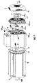
- FIG. 1 is an exploded view an electric drive system with motor M, integrated Converter and integrated drive electronics AE shown, which is forced ventilation according to the present invention enables.
- an electric motor M is shown, the Motor shaft MW A-side A is led out of the motor housing.
- B-sided B is an add-on housing AG for the integration of the drive electronics AE provided, which is on the B-sided Engine end shield is attached. This attachment housing AG is designed so that the interference contour (mounting format) of the motor M is injured as little as possible.
- the attachment housing AG preferably has a concept small length, which increases the volume of the electrical Drive system can be minimized.
- a separate LM fan motor integrated for the purpose of forced ventilation is also B-side B in the attachment housing AG arranged so that the fan motor shaft LMW the B-side B of the electric drive system, i.e. from the A-side A is arranged facing away.
- the fan motor shaft LMW of the fan motor LM is led to the outside through a bearing plate L of the mounting housing AG arranged on the B side and drives an external fan wheel LR ext .
- the fan motor shaft LMW can either be guided to the outside via a shaft seal with the appropriate degree of protection, or it can drive a second shaft via a coupling, which is guided to the outside via the end shield L with the corresponding degree of protection and drives the internal fan wheel LR ext .
- several fan motors, each with an assigned external fan wheel can be provided.
- an arrangement with only one fan motor LM is shown in the exemplary embodiment, which drives a single external fan wheel LR ext .
- the circuit breakers of the AE drive electronics are also advantageously mounted on the B side in the AG mounting housing.
- the bearing plate L of the attachment housing AG has radial cooling fins KR radially .
- the add-on housing AG has axial cooling channels KK axial .
- axial cooling fins could also be arranged distributed over the circumference of the attachment housing. Such a measure is also possible in addition.
- a hood H is attached on the B side, which has axial air inlet slots and radial air outlet slots.
- this hood H secures the external fan wheel LR ext , on the other hand it serves for the suitable guidance of an air flow LS.
- the external fan wheel LR ext now draws in air on the B side and redirects this air radially. Radially deflected air is guided radially on the end shield L2 via the radially arranged cooling fins KR. Since the circuit breakers of the drive electronics AE are also mounted on the B side, these circuit breakers give their heat loss to the end shield L preferably. This heat loss can be dissipated radially by the axially deflected air flow LS via the radial cooling fins KR. Thus, the radial cooling fins are mainly intended for the dissipation of the power unit's power loss (switching and forward losses of the circuit breakers).
- the hood on the housing B-side optimizes the guidance of the air flow LS in such a way that part of the radially deflected air flow exits through the radial air outlet slots of the cover H and the other part of the air flow LS is passed axially through the cover H via the attachment housing AG.
- This axially forwarded air flow is thus guided axially through the axial cooling channels KK or, if present, via axial cooling fins.
- These axial cooling channels KK axial or axial cooling fins are mainly used to dissipate the electronic power loss.
- the axial air flow mentioned can thus also be passed on over the surface of the motor M, the motor M likewise being able to have cooling fins or cooling channels. As a result, most of the heat generated in the motor M itself can be dissipated.
- the fan motor LM has a further internal fan wheel LR int on its B side B2, through which air swirling can be achieved within the attachment housing AG.
- This air turbulence can significantly improve the heat dissipation due to the heat exchanger principle. This has the advantage that the cooling concept according to the present invention enables a very small fan output.
- the cooling concept then used according to the present invention if the motor shaft MW B-side B through the attachment housing AG must be brought out.
- the LM fan motor can be designed as a hollow shaft motor and then an external hollow shaft fan wheel via belts or gears operate.
- a fan motor LM as in the embodiment according to the 1 is shown, arranged eccentrically and also via a belt or gear coupling Hollow shaft fan wheel drives.
- several eccentrically arranged fan motors with corresponding external and internal fan wheels can be used.
- the B-side end shield L1 of the motor M and the Drive electronics AE in the mounting housing AG is in the embodiment as shown in FIG 1 also a Insulation washer D made of a heat-insulating material (e.g. fiber optic amplifier plastic) provided to the power loss (Heat) of the motor M from the power loss of the drive electronics Decouple AE.
- a heat-insulating material e.g. fiber optic amplifier plastic
- the B-side end shield L1 of the motor M for Heat decoupling made of a heat insulating material is.
- Such an encoder system G arranged after the heat decoupling on the part of the attachment housing AG.
Landscapes
- Engineering & Computer Science (AREA)
- Power Engineering (AREA)
- Physics & Mathematics (AREA)
- Thermal Sciences (AREA)
- Microelectronics & Electronic Packaging (AREA)
- Control Of Electric Motors In General (AREA)
- Control Of Multiple Motors (AREA)
- Motor Or Generator Cooling System (AREA)
Applications Claiming Priority (2)
| Application Number | Priority Date | Filing Date | Title |
|---|---|---|---|
| DE29700643U | 1997-01-15 | ||
| DE29700643U DE29700643U1 (de) | 1997-01-15 | 1997-01-15 | Entwärmungskonzept für ein elektrisches Antriebssystem |
Publications (1)
| Publication Number | Publication Date |
|---|---|
| EP0854560A1 true EP0854560A1 (fr) | 1998-07-22 |
Family
ID=8034608
Family Applications (1)
| Application Number | Title | Priority Date | Filing Date |
|---|---|---|---|
| EP98100161A Withdrawn EP0854560A1 (fr) | 1997-01-15 | 1998-01-07 | Concept d'évacuation de chaleur pour entranement électrique |
Country Status (2)
| Country | Link |
|---|---|
| EP (1) | EP0854560A1 (fr) |
| DE (1) | DE29700643U1 (fr) |
Cited By (17)
| Publication number | Priority date | Publication date | Assignee | Title |
|---|---|---|---|---|
| WO2003065547A1 (fr) * | 2002-01-28 | 2003-08-07 | Sew-Eurodrive Gmbh & Co | Moteur electrique et gamme de fabrication |
| EP1582751A1 (fr) * | 2004-04-02 | 2005-10-05 | Grundfos a/s | Unité de pompage |
| DE102004031399B4 (de) * | 2004-06-29 | 2007-04-12 | Siemens Ag | Umrichtermotor |
| CN103904813A (zh) * | 2012-12-25 | 2014-07-02 | 中山大洋电机股份有限公司 | 一种大功率电机散热结构 |
| CN103997140A (zh) * | 2014-05-29 | 2014-08-20 | 江阴市曾氏动力机械科技有限公司 | 一种内外双风冷发电机 |
| DE102013224430A1 (de) * | 2013-11-28 | 2015-05-28 | Siemens Aktiengesellschaft | Elektrisches Antriebssystem |
| WO2016155933A1 (fr) * | 2015-04-02 | 2016-10-06 | Robert Bosch Gmbh | Structure d'ailettes de refroidissement pour le refroidissement, indépendant de la position de montage, d'un boîtier |
| EP2973957A4 (fr) * | 2013-03-15 | 2016-12-14 | Regal Beloit Australia Pty Ltd | Machine électrique refroidie à l'air et son procédé d'assemblage |
| DE102015009540A1 (de) * | 2015-07-28 | 2017-02-02 | Sew-Eurodrive Gmbh & Co Kg | Elektromotor mit Lüfter, Lüfterhaube, Motorgehäuse, aufweisend Gehäuseteil, Flanschteil und Statorgehäuse |
| EP3719973A1 (fr) * | 2019-04-04 | 2020-10-07 | Siemens Aktiengesellschaft | Unité d'entraînement dotée d'une unité d'aérateur |
| EP3719969A1 (fr) * | 2019-04-04 | 2020-10-07 | Siemens Aktiengesellschaft | Unité d'entraînement dotée d'un système d'aération |
| DE102020104203A1 (de) | 2020-02-18 | 2021-08-19 | ITURRI Feuerwehr- und Umwelttechnik GmbH | Fördereinrichtung für Flüssigkeiten mit elektrischem Antrieb |
| US11139722B2 (en) | 2018-03-02 | 2021-10-05 | Black & Decker Inc. | Motor having an external heat sink for a power tool |
| EP3906608A1 (fr) * | 2019-04-04 | 2021-11-10 | Siemens Aktiengesellschaft | Unité d'entraînement pourvue d'une unité de refroidissement |
| EP4002655A1 (fr) | 2020-11-24 | 2022-05-25 | Siemens Aktiengesellschaft | Moteur électrique et robot pourvu de moteur électrique |
| EP4050773A3 (fr) * | 2021-02-25 | 2022-09-14 | Regal Beloit America, Inc. | Ensemble machine électrique avec refroidissement du cadre d'extrémité |
| EP4712318A1 (fr) | 2024-09-12 | 2026-03-18 | Innomotics GmbH | Convertisseur intégré à un moteur avec élément de blindage |
Families Citing this family (7)
| Publication number | Priority date | Publication date | Assignee | Title |
|---|---|---|---|---|
| EP0883228B1 (fr) * | 1997-06-03 | 2005-03-30 | Frankl & Kirchner GmbH. & Co. KG Fabrik für Elektromotoren und elektrische Apparate | Moteur électrique |
| DE19859930A1 (de) * | 1998-12-24 | 2000-06-29 | Dietz Motoren Gmbh & Co Kg | Elektromotoranordnung |
| DE102004037079A1 (de) * | 2004-07-30 | 2006-03-23 | Siemens Ag | Elektrischer Kompaktantrieb |
| DE102008003863A1 (de) * | 2008-01-10 | 2009-07-16 | Jungheinrich Ag | Elektrischer Antrieb für ein Flurförderzeug |
| DE102013205133A1 (de) * | 2013-03-22 | 2014-09-25 | Schaeffler Technologies Gmbh & Co. Kg | Motor für einen Direktantrieb eines Drehtisches |
| US10177633B2 (en) * | 2014-12-23 | 2019-01-08 | Abb Schweiz Ag | Multiphase fractional slot concentrated winding machine with end mounted detachable or integrated multiphase series converter circuit |
| WO2018227489A1 (fr) * | 2017-06-15 | 2018-12-20 | 深圳市大疆创新科技有限公司 | Capuchon d'extrémité de moteur électrique, moteur électrique, centrale électrique et aéronef |
Citations (3)
| Publication number | Priority date | Publication date | Assignee | Title |
|---|---|---|---|---|
| GB2214722A (en) * | 1988-01-15 | 1989-09-06 | Ass Elect Ind | Conjoint cooling of electric motor and its controller |
| DE9305174U1 (de) * | 1993-04-05 | 1993-11-04 | Franz Morat KG Elektro-Feinmechanik & Maschinenbau (GmbH & Co), 79871 Eisenbach | Drehstrom-Asynchronmotor mit Frequenzumrichter |
| DE19511114C1 (de) * | 1995-03-25 | 1996-08-29 | Grundfos As | Elektromotor |
-
1997
- 1997-01-15 DE DE29700643U patent/DE29700643U1/de not_active Expired - Lifetime
-
1998
- 1998-01-07 EP EP98100161A patent/EP0854560A1/fr not_active Withdrawn
Patent Citations (3)
| Publication number | Priority date | Publication date | Assignee | Title |
|---|---|---|---|---|
| GB2214722A (en) * | 1988-01-15 | 1989-09-06 | Ass Elect Ind | Conjoint cooling of electric motor and its controller |
| DE9305174U1 (de) * | 1993-04-05 | 1993-11-04 | Franz Morat KG Elektro-Feinmechanik & Maschinenbau (GmbH & Co), 79871 Eisenbach | Drehstrom-Asynchronmotor mit Frequenzumrichter |
| DE19511114C1 (de) * | 1995-03-25 | 1996-08-29 | Grundfos As | Elektromotor |
Cited By (30)
| Publication number | Priority date | Publication date | Assignee | Title |
|---|---|---|---|---|
| WO2003065547A1 (fr) * | 2002-01-28 | 2003-08-07 | Sew-Eurodrive Gmbh & Co | Moteur electrique et gamme de fabrication |
| EP1582751A1 (fr) * | 2004-04-02 | 2005-10-05 | Grundfos a/s | Unité de pompage |
| DE102004031399B4 (de) * | 2004-06-29 | 2007-04-12 | Siemens Ag | Umrichtermotor |
| CN103904813A (zh) * | 2012-12-25 | 2014-07-02 | 中山大洋电机股份有限公司 | 一种大功率电机散热结构 |
| CN103904813B (zh) * | 2012-12-25 | 2016-05-04 | 中山大洋电机股份有限公司 | 一种大功率电机散热结构 |
| EP2973957A4 (fr) * | 2013-03-15 | 2016-12-14 | Regal Beloit Australia Pty Ltd | Machine électrique refroidie à l'air et son procédé d'assemblage |
| DE102013224430A1 (de) * | 2013-11-28 | 2015-05-28 | Siemens Aktiengesellschaft | Elektrisches Antriebssystem |
| DE102013224430B4 (de) * | 2013-11-28 | 2016-02-18 | Siemens Aktiengesellschaft | Elektrisches Antriebssystem |
| CN103997140A (zh) * | 2014-05-29 | 2014-08-20 | 江阴市曾氏动力机械科技有限公司 | 一种内外双风冷发电机 |
| WO2016155933A1 (fr) * | 2015-04-02 | 2016-10-06 | Robert Bosch Gmbh | Structure d'ailettes de refroidissement pour le refroidissement, indépendant de la position de montage, d'un boîtier |
| DE102015009540A1 (de) * | 2015-07-28 | 2017-02-02 | Sew-Eurodrive Gmbh & Co Kg | Elektromotor mit Lüfter, Lüfterhaube, Motorgehäuse, aufweisend Gehäuseteil, Flanschteil und Statorgehäuse |
| US11139722B2 (en) | 2018-03-02 | 2021-10-05 | Black & Decker Inc. | Motor having an external heat sink for a power tool |
| WO2020200627A1 (fr) * | 2019-04-04 | 2020-10-08 | Siemens Aktiengesellschaft | Unité d'entraînement pourvue d'un système d'aération |
| US12188487B2 (en) | 2019-04-04 | 2025-01-07 | Innomotics Gmbh | Drive unit having a cooling unit |
| EP3719969A1 (fr) * | 2019-04-04 | 2020-10-07 | Siemens Aktiengesellschaft | Unité d'entraînement dotée d'un système d'aération |
| WO2020200629A1 (fr) * | 2019-04-04 | 2020-10-08 | Siemens Aktiengesellschaft | Unité d'entraînement pourvue d'une unité ventilateur |
| EP3719973A1 (fr) * | 2019-04-04 | 2020-10-07 | Siemens Aktiengesellschaft | Unité d'entraînement dotée d'une unité d'aérateur |
| EP3906608A1 (fr) * | 2019-04-04 | 2021-11-10 | Siemens Aktiengesellschaft | Unité d'entraînement pourvue d'une unité de refroidissement |
| DE102020104203A1 (de) | 2020-02-18 | 2021-08-19 | ITURRI Feuerwehr- und Umwelttechnik GmbH | Fördereinrichtung für Flüssigkeiten mit elektrischem Antrieb |
| EP4002655A1 (fr) | 2020-11-24 | 2022-05-25 | Siemens Aktiengesellschaft | Moteur électrique et robot pourvu de moteur électrique |
| EP4050773A3 (fr) * | 2021-02-25 | 2022-09-14 | Regal Beloit America, Inc. | Ensemble machine électrique avec refroidissement du cadre d'extrémité |
| US12149147B2 (en) | 2021-02-25 | 2024-11-19 | Regal Beloit America, Inc. | Electric machine assembly having a terminal box |
| US12218561B2 (en) | 2021-02-25 | 2025-02-04 | Regal Beloit America, Inc. | Electric machine assembly having a rotor frame to provide cooling |
| US12249893B2 (en) | 2021-02-25 | 2025-03-11 | Regal Beloit America, Inc. | Electric machine assembly having an internal fan |
| US12381441B2 (en) | 2021-02-25 | 2025-08-05 | Regal Beloit America, Inc. | Electric machine assembly having end frame cooling |
| US12381442B2 (en) | 2021-02-25 | 2025-08-05 | Regal Beloit America, Inc. | Electric machine assembly |
| US12470108B2 (en) | 2021-02-25 | 2025-11-11 | Regal Beloit America, Inc. | Electric machine assembly having a rotatable terminal box |
| US12476515B2 (en) | 2021-02-25 | 2025-11-18 | Regal Beloit America, Inc. | Electric machine assembly having a wire guiding structure |
| EP4712318A1 (fr) | 2024-09-12 | 2026-03-18 | Innomotics GmbH | Convertisseur intégré à un moteur avec élément de blindage |
| WO2026057541A1 (fr) | 2024-09-12 | 2026-03-19 | Innomotics Gmbh | Onduleur intégré à un moteur comprenant un élément de protection |
Also Published As
| Publication number | Publication date |
|---|---|
| DE29700643U1 (de) | 1997-03-13 |
Similar Documents
| Publication | Publication Date | Title |
|---|---|---|
| EP0854560A1 (fr) | Concept d'évacuation de chaleur pour entranement électrique | |
| EP0513014B1 (fr) | Machine electrique a ventilation forcee | |
| EP0735650B1 (fr) | Moteur électrique | |
| EP1937978B1 (fr) | Ventilateur de radiateur pour un vehicule a moteur | |
| DE69827376T2 (de) | Kompaktantrieb | |
| DE69021808T2 (de) | Ein Kühlgebläse für eine drehende elektrische Maschine. | |
| DE19636591C2 (de) | Synchrongenerator für einen getriebelosen Windenergiekonverter | |
| DE102004054601B4 (de) | Kompaktantrieb, Spiroplangetriebe und Verfahren zur Fertigung eines Antriebs | |
| EP0574731A1 (fr) | Machine outil à main à moteur ventilé | |
| DE10052331A1 (de) | Lüfteranlage | |
| DE3313747C2 (de) | Elektrische Maschine | |
| EP3719961A1 (fr) | Unité d'entraînement doté d'un refroidissement d'arbre | |
| DE19919040C2 (de) | Synchronmaschine oder Asychronmaschine für große Windenergieanlagen | |
| DE2007194A1 (de) | Kühlgasführung bei elektrischen Maschinen | |
| EP0522210B1 (fr) | Système de refroidissement pour une machine électrique à rotation et machine électrique pour réaliser un tel système | |
| EP1524751B1 (fr) | Moteur électrique sans balai | |
| DE102006052111A1 (de) | Elektrische Maschine | |
| EP0788779B1 (fr) | Moteur à courant continu pour l'entraínement d'un instrument dentaire | |
| EP1516109B1 (fr) | Dispositif de refroidissement d'unite generatrice de courant | |
| DE102005032970B3 (de) | Umrichtermotor | |
| DE3137172C2 (fr) | ||
| DE102014009315A1 (de) | Verfahren zum Herstellen von verschiedenen Varianten eines Antriebs aus einem Baukasten und Antrieb nach einem solchen Verfahren | |
| DE8321093U1 (de) | Rueckkuehlanordnung fuer eine geschlossene elektrische maschine | |
| DE4131966A1 (de) | Wechselstromgenerator fuer fahrzeuge | |
| DE10225221B4 (de) | Belüftung eines Ringmotors für eine Rohrmühle |
Legal Events
| Date | Code | Title | Description |
|---|---|---|---|
| PUAI | Public reference made under article 153(3) epc to a published international application that has entered the european phase |
Free format text: ORIGINAL CODE: 0009012 |
|
| AK | Designated contracting states |
Kind code of ref document: A1 Designated state(s): AT CH DE ES FR GB IT LI SE |
|
| AX | Request for extension of the european patent |
Free format text: AL;LT;LV;MK;RO;SI |
|
| 17P | Request for examination filed |
Effective date: 19980805 |
|
| AKX | Designation fees paid |
Free format text: AT CH DE ES FR GB IT LI SE |
|
| RBV | Designated contracting states (corrected) |
Designated state(s): AT CH DE ES FR GB IT LI SE |
|
| STAA | Information on the status of an ep patent application or granted ep patent |
Free format text: STATUS: THE APPLICATION IS DEEMED TO BE WITHDRAWN |
|
| 18D | Application deemed to be withdrawn |
Effective date: 20000801 |