EP4002655A1 - Moteur électrique et robot pourvu de moteur électrique - Google Patents
Moteur électrique et robot pourvu de moteur électrique Download PDFInfo
- Publication number
- EP4002655A1 EP4002655A1 EP20209484.3A EP20209484A EP4002655A1 EP 4002655 A1 EP4002655 A1 EP 4002655A1 EP 20209484 A EP20209484 A EP 20209484A EP 4002655 A1 EP4002655 A1 EP 4002655A1
- Authority
- EP
- European Patent Office
- Prior art keywords
- electric motor
- housing
- opening
- end winding
- stator
- Prior art date
- Legal status (The legal status is an assumption and is not a legal conclusion. Google has not performed a legal analysis and makes no representation as to the accuracy of the status listed.)
- Withdrawn
Links
- 238000004804 winding Methods 0.000 claims abstract description 30
- 239000002826 coolant Substances 0.000 claims abstract description 12
- 238000001816 cooling Methods 0.000 claims abstract description 8
- 239000003570 air Substances 0.000 description 18
- 238000009423 ventilation Methods 0.000 description 3
- 230000001360 synchronised effect Effects 0.000 description 2
- 239000012080 ambient air Substances 0.000 description 1
- 238000005266 casting Methods 0.000 description 1
- 238000010276 construction Methods 0.000 description 1
- 238000011109 contamination Methods 0.000 description 1
- 230000007613 environmental effect Effects 0.000 description 1
- 238000009434 installation Methods 0.000 description 1
- 238000005457 optimization Methods 0.000 description 1
- 239000011347 resin Substances 0.000 description 1
- 229920005989 resin Polymers 0.000 description 1
- 239000002918 waste heat Substances 0.000 description 1
Images

Classifications
-
- H—ELECTRICITY
- H02—GENERATION; CONVERSION OR DISTRIBUTION OF ELECTRIC POWER
- H02K—DYNAMO-ELECTRIC MACHINES
- H02K9/00—Arrangements for cooling or ventilating
- H02K9/02—Arrangements for cooling or ventilating by ambient air flowing through the machine
- H02K9/04—Arrangements for cooling or ventilating by ambient air flowing through the machine having means for generating a flow of cooling medium
- H02K9/06—Arrangements for cooling or ventilating by ambient air flowing through the machine having means for generating a flow of cooling medium with fans or impellers driven by the machine shaft
-
- H—ELECTRICITY
- H02—GENERATION; CONVERSION OR DISTRIBUTION OF ELECTRIC POWER
- H02K—DYNAMO-ELECTRIC MACHINES
- H02K11/00—Structural association of dynamo-electric machines with electric components or with devices for shielding, monitoring or protection
- H02K11/30—Structural association with control circuits or drive circuits
- H02K11/33—Drive circuits, e.g. power electronics
-
- H—ELECTRICITY
- H02—GENERATION; CONVERSION OR DISTRIBUTION OF ELECTRIC POWER
- H02K—DYNAMO-ELECTRIC MACHINES
- H02K7/00—Arrangements for handling mechanical energy structurally associated with dynamo-electric machines, e.g. structural association with mechanical driving motors or auxiliary dynamo-electric machines
- H02K7/10—Structural association with clutches, brakes, gears, pulleys or mechanical starters
- H02K7/102—Structural association with clutches, brakes, gears, pulleys or mechanical starters with friction brakes
Definitions
- the invention relates to an electric motor with a stator with windings which comprise a first end winding and a second end winding, a rotor with a shaft, a housing having a first end plate and a second end plate, an impeller arranged inside the housing axially to the shaft, which is designed to generate a negative pressure.
- the invention also relates to a robot with an electric motor.
- Electric motors which drive a mechanical load at one axial end and have fans and/or brakes at their other end.
- Fan cowls are also known, which are fastened to an end shield of the electric motor with screws. From the EP 0 942 513 A2 and the EP 1 472 773 B1 electric motors with ventilation cooling are known.
- the object of the invention is to implement cooling that is as compact and cost-effective as possible in an electric motor.
- a suction opening is located in the housing between the first bearing plate and the first end winding side of the stator is arranged such that a cooling medium flows from outside the housing due to the negative pressure past the first end winding side into an air gap between the stator and the rotor, furthermore an outlet opening is arranged in the housing in such a way that the cooling medium flows out of the Air gap flows out of the housing on the second end winding overhang.
- the impeller therefore generates a negative pressure on the second end winding side and an overpressure on the side facing the outlet opening, so that the cooling medium is drawn through the air gap.
- an electric motor with a self-contained cooling has been created.
- the cooling medium is the ambient air
- air is introduced by the negative pressure, which is generated, for example, with a centrifugal fan and generates the negative pressure in a targeted manner in the area of the shaft and the air is thus drawn through the air gap of the electric motor.
- the stator to be encapsulated with the winding.
- Protecting the electrical components inside the motor and the permanent magnets from dirt and moisture is particularly important for robot motors that work in harsh environmental conditions. Since, according to the invention, a cooling medium is drawn through the air gap of the motor under high pressure, i.e. also at a high flow rate, contamination within the air gap could have fatal consequences. For example, with a 600 volt electric motor, it is not so easy to implement ventilation because the air and creepage distances for currents and voltages have to be maintained there. Accordingly, for protection, the stator, for example, is encapsulated or encapsulated with casting resin.
- a fan wheel is preferably connected to the brake disk or integrated into it, no additional installation space is required and, as a further advantage, the brake is additionally cooled.
- the braking energy is also dissipated.
- the brake is usually located in the axial direction next to the active part of the motor. The air is then discharged on the braking side and the air is sucked in on the opposite side.
- the electric motor additionally has a converter, the converter then being arranged between the first end shield and the first end winding side.
- a filter element can also be arranged in the intake opening.
- a robot with an electric motor comprising a robot housing which has at least one inflow opening and one outflow opening, the inflow opening being connected to the suction opening and the outflow opening being connected to the exhaust opening.
- the invention can be applied in particular to a permanently excited synchronous machine. Accordingly, a fan impeller is used as the impeller that generates negative pressure, which sits on the motor shaft and draws air into the motor during operation. In the case of built-in motors (including converter, motor, brake and gearbox), the air is then drawn through the housing via the motor. For a particularly space-saving design, a fan wheel is combined with the brake disk of a holding brake.
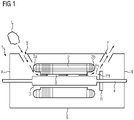
- an electric motor 1 comprising a stator 2 with windings, which comprise a first winding head side 2a and a second winding head side 2b.
- the electric motor 1 is shown schematically in a sectional view.
- a rotor 3 is connected to a shaft 4 .
- a housing 5 is designed such that the housing is a first Bearing plate A and a second bearing plate B has. Inside the housing 5, a vacuum-generating impeller R is arranged axially to the shaft.
- the impeller R can be designed, for example, as a fan wheel or as a centrifugal fan or as a compressor element.
- a suction opening 6 is arranged in the housing 5 between the first end shield A and the first end winding side 2a of the stator 2 in such a way that a cooling medium L from outside the housing 5 due to the negative pressure P1 can flow past the first end winding side 2a into an air gap 8 between the stator 2 and the rotor 3 flows. So that the cooling medium L that has been drawn in can absorb the heat and leave the electric motor 1 again, a blow-out opening 7 is arranged in such a way that the cooling medium L out of the air gap 8, past the second end winding side 2b, in the vicinity of which the impeller R is also arranged , can flow out of the housing 5 again.
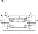
- FIG 2 an arrangement of an electric motor 1 with a holding brake 9 is shown. If the impeller R is integrated into a brake disc 9a of the holding brake 9, a particularly compact and space-saving design is achieved and the electric motor 1 can still be cooled.
- the arrows symbolically show the air flow from the intake opening 6 to the exhaust opening 7 .
- the impeller R is arranged at the location of the second end winding side 2b, a cooling air flow can be sucked completely through the motor.
- a further optimization is achieved if an additional vacuum-generating impeller R z is arranged below the intake opening 6 or in the vicinity of the intake opening 6 .
- an additional vacuum-generating impeller R z is arranged below the intake opening 6 or in the vicinity of the intake opening 6 .
- this can also be cooled.
- a lightweight construction for a robot 30 shows the 3 the use of the invention Electric motor 1 within a robot housing 31.
- the robot 30 with its built-in electric motor 1 has an inflow opening 32 and an outflow opening 33 within its robot housing 31, preferably in the vicinity of the electric motor 1.
- the inflow opening 32 of the robot housing 31 is in contact with the suction opening 6 of the electric motor 1 Connection and the outflow opening 33 within the robot housing 31 communicates with the exhaust opening 7 in combination.
Landscapes
- Engineering & Computer Science (AREA)
- Power Engineering (AREA)
- Microelectronics & Electronic Packaging (AREA)
- Motor Or Generator Cooling System (AREA)
Priority Applications (1)
| Application Number | Priority Date | Filing Date | Title |
|---|---|---|---|
| EP20209484.3A EP4002655A1 (fr) | 2020-11-24 | 2020-11-24 | Moteur électrique et robot pourvu de moteur électrique |
Applications Claiming Priority (1)
| Application Number | Priority Date | Filing Date | Title |
|---|---|---|---|
| EP20209484.3A EP4002655A1 (fr) | 2020-11-24 | 2020-11-24 | Moteur électrique et robot pourvu de moteur électrique |
Publications (1)
| Publication Number | Publication Date |
|---|---|
| EP4002655A1 true EP4002655A1 (fr) | 2022-05-25 |
Family
ID=73554319
Family Applications (1)
| Application Number | Title | Priority Date | Filing Date |
|---|---|---|---|
| EP20209484.3A Withdrawn EP4002655A1 (fr) | 2020-11-24 | 2020-11-24 | Moteur électrique et robot pourvu de moteur électrique |
Country Status (1)
| Country | Link |
|---|---|
| EP (1) | EP4002655A1 (fr) |
Citations (9)
| Publication number | Priority date | Publication date | Assignee | Title |
|---|---|---|---|---|
| EP0854560A1 (fr) | 1997-01-15 | 1998-07-22 | Siemens Aktiengesellschaft | Concept d'évacuation de chaleur pour entranement électrique |
| EP0942513A2 (fr) | 1998-03-10 | 1999-09-15 | ATB Austria Antriebstechnik Aktiengesellschaft | Moteur électrique |
| DE102004063751A1 (de) * | 2004-12-29 | 2006-07-13 | Robert Bosch Gmbh | Elektrohandwerkzeugmaschine |
| DE102008041370A1 (de) * | 2008-08-20 | 2010-02-25 | Robert Bosch Gmbh | Elektrowerkzeug |
| EP2689897A1 (fr) * | 2011-03-23 | 2014-01-29 | Panasonic Corporation | Outil motorisé |
| DE102013224430A1 (de) * | 2013-11-28 | 2015-05-28 | Siemens Aktiengesellschaft | Elektrisches Antriebssystem |
| EP3173170A1 (fr) * | 2015-11-25 | 2017-05-31 | Panasonic Intellectual Property Management Co., Ltd. | Outil électrique |
| EP1472773B1 (fr) | 2002-01-28 | 2019-05-22 | SEW-Eurodrive GmbH & Co | Moteur électrique et gamme de fabrication |
| CN111711315A (zh) * | 2020-07-16 | 2020-09-25 | 宁波奔逸新能源科技有限公司 | 一种带刹车装置的电机 |
-
2020
- 2020-11-24 EP EP20209484.3A patent/EP4002655A1/fr not_active Withdrawn
Patent Citations (9)
| Publication number | Priority date | Publication date | Assignee | Title |
|---|---|---|---|---|
| EP0854560A1 (fr) | 1997-01-15 | 1998-07-22 | Siemens Aktiengesellschaft | Concept d'évacuation de chaleur pour entranement électrique |
| EP0942513A2 (fr) | 1998-03-10 | 1999-09-15 | ATB Austria Antriebstechnik Aktiengesellschaft | Moteur électrique |
| EP1472773B1 (fr) | 2002-01-28 | 2019-05-22 | SEW-Eurodrive GmbH & Co | Moteur électrique et gamme de fabrication |
| DE102004063751A1 (de) * | 2004-12-29 | 2006-07-13 | Robert Bosch Gmbh | Elektrohandwerkzeugmaschine |
| DE102008041370A1 (de) * | 2008-08-20 | 2010-02-25 | Robert Bosch Gmbh | Elektrowerkzeug |
| EP2689897A1 (fr) * | 2011-03-23 | 2014-01-29 | Panasonic Corporation | Outil motorisé |
| DE102013224430A1 (de) * | 2013-11-28 | 2015-05-28 | Siemens Aktiengesellschaft | Elektrisches Antriebssystem |
| EP3173170A1 (fr) * | 2015-11-25 | 2017-05-31 | Panasonic Intellectual Property Management Co., Ltd. | Outil électrique |
| CN111711315A (zh) * | 2020-07-16 | 2020-09-25 | 宁波奔逸新能源科技有限公司 | 一种带刹车装置的电机 |
Similar Documents
| Publication | Publication Date | Title |
|---|---|---|
| EP2880745B1 (fr) | Refroidissement actif de moteur avec conduit de refroidissement intégré | |
| DE112008002995B4 (de) | Motor mit Kühlstruktur | |
| EP2017435A2 (fr) | Turbomachine avec machine électrique et paliers magnétiques | |
| DE20204729U1 (de) | Gebläse mit eingebauten Selbstkühleigenschaften | |
| DE102016004714A1 (de) | Spinnrotorschaft, Lageranordnung zum aktiven magnetischen Lagern eines solchen Spinnrotorschafts und Spinnrotorantriebseinrichtung | |
| EP2217407A1 (fr) | Machine-outil électrique équipée d'un moteur électrique | |
| DE102007039186A1 (de) | Läufer eines Traktionsmotors | |
| DE102015215009A1 (de) | Luftgekühlter Elektromotor mit einer Parallelschaltung zweier Lüfterräder | |
| EP1024295A1 (fr) | Entraínement pour moteur éléctrique | |
| DE102014106455A1 (de) | Elektromaschine für den Einsatz im KFZ-Bereich | |
| EP4229740A1 (fr) | Pompe centrifuge comprenant un entraînement | |
| AT510358B1 (de) | Permanentmagneterregte elektrische maschine | |
| EP2445090A1 (fr) | Machine dynamoélectrique dotée d'un dispositif de frein d'arrêt | |
| EP3447299B1 (fr) | Rondelle de calage | |
| EP4002655A1 (fr) | Moteur électrique et robot pourvu de moteur électrique | |
| EP0899852A1 (fr) | Moulage coulé d'un moteur électrique | |
| EP4256199B1 (fr) | Agencement d'engrenage et de générateur comprenant un frein pour éolienne | |
| EP4006348B1 (fr) | Ventilateur doté d'un moteur à rotor externe et canal de refroidissement destiné au refroidissement de l'électronique du moteur et des composants d'entraînement du moteur | |
| EP0582217A1 (fr) | Module redresseur de courant refroidi par liquide avec un courant de refroidissement obtenu par une pompe de refroidissement | |
| EP3595144A1 (fr) | Unité de traction à ventilateur intégré | |
| DE102020006365A1 (de) | Kreiselpumpe mit einem Antrieb | |
| EP1109297B1 (fr) | Moteur électrique d'entraínement refroidi par ventilateur | |
| DE9404147U1 (de) | Axiallüfter | |
| DE7731930U1 (de) | Elektromotor mit einem auf einem wellenende befestigten spinnrotor fuer open-end-spinnmaschinen | |
| WO2008000642A1 (fr) | Machine électrique, en particulier alternateur à courant triphasé et dispositif de refroidissement pour machine électrique |
Legal Events
| Date | Code | Title | Description |
|---|---|---|---|
| PUAI | Public reference made under article 153(3) epc to a published international application that has entered the european phase |
Free format text: ORIGINAL CODE: 0009012 |
|
| STAA | Information on the status of an ep patent application or granted ep patent |
Free format text: STATUS: THE APPLICATION HAS BEEN PUBLISHED |
|
| AK | Designated contracting states |
Kind code of ref document: A1 Designated state(s): AL AT BE BG CH CY CZ DE DK EE ES FI FR GB GR HR HU IE IS IT LI LT LU LV MC MK MT NL NO PL PT RO RS SE SI SK SM TR |
|
| STAA | Information on the status of an ep patent application or granted ep patent |
Free format text: STATUS: THE APPLICATION IS DEEMED TO BE WITHDRAWN |
|
| 18D | Application deemed to be withdrawn |
Effective date: 20221126 |