EP0854564B1 - Wechselstrom-Gleichstromwandler mit einem piezoelektrischen Transformator - Google Patents
Wechselstrom-Gleichstromwandler mit einem piezoelektrischen Transformator Download PDFInfo
- Publication number
- EP0854564B1 EP0854564B1 EP98100639A EP98100639A EP0854564B1 EP 0854564 B1 EP0854564 B1 EP 0854564B1 EP 98100639 A EP98100639 A EP 98100639A EP 98100639 A EP98100639 A EP 98100639A EP 0854564 B1 EP0854564 B1 EP 0854564B1
- Authority
- EP
- European Patent Office
- Prior art keywords
- piezoelectric transformer
- transformer
- output
- voltage
- converter
- Prior art date
- Legal status (The legal status is an assumption and is not a legal conclusion. Google has not performed a legal analysis and makes no representation as to the accuracy of the status listed.)
- Expired - Lifetime
Links
- 239000003990 capacitor Substances 0.000 claims description 20
- 238000009499 grossing Methods 0.000 claims description 18
- 238000010586 diagram Methods 0.000 description 6
- 239000000919 ceramic Substances 0.000 description 2
- 238000006243 chemical reaction Methods 0.000 description 2
- 238000009413 insulation Methods 0.000 description 2
- 239000004973 liquid crystal related substance Substances 0.000 description 2
- 230000001131 transforming effect Effects 0.000 description 2
- 238000004804 winding Methods 0.000 description 2
- XAGFODPZIPBFFR-UHFFFAOYSA-N aluminium Chemical compound [Al] XAGFODPZIPBFFR-UHFFFAOYSA-N 0.000 description 1
- 229910052782 aluminium Inorganic materials 0.000 description 1
- 230000004888 barrier function Effects 0.000 description 1
- 230000005669 field effect Effects 0.000 description 1
- 125000006850 spacer group Chemical group 0.000 description 1
Images





Classifications
-
- H—ELECTRICITY
- H10—SEMICONDUCTOR DEVICES; ELECTRIC SOLID-STATE DEVICES NOT OTHERWISE PROVIDED FOR
- H10N—ELECTRIC SOLID-STATE DEVICES NOT OTHERWISE PROVIDED FOR
- H10N30/00—Piezoelectric or electrostrictive devices
- H10N30/40—Piezoelectric or electrostrictive devices with electrical input and electrical output, e.g. functioning as transformers
-
- H—ELECTRICITY
- H02—GENERATION; CONVERSION OR DISTRIBUTION OF ELECTRIC POWER
- H02M—APPARATUS FOR CONVERSION BETWEEN AC AND AC, BETWEEN AC AND DC, OR BETWEEN DC AND DC, AND FOR USE WITH MAINS OR SIMILAR POWER SUPPLY SYSTEMS; CONVERSION OF DC OR AC INPUT POWER INTO SURGE OUTPUT POWER; CONTROL OR REGULATION THEREOF
- H02M7/00—Conversion of AC power input into DC power output; Conversion of DC power input into AC power output
- H02M7/02—Conversion of AC power input into DC power output without possibility of reversal
- H02M7/04—Conversion of AC power input into DC power output without possibility of reversal by static converters
- H02M7/12—Conversion of AC power input into DC power output without possibility of reversal by static converters using discharge tubes with control electrode or semiconductor devices with control electrode
-
- H—ELECTRICITY
- H02—GENERATION; CONVERSION OR DISTRIBUTION OF ELECTRIC POWER
- H02M—APPARATUS FOR CONVERSION BETWEEN AC AND AC, BETWEEN AC AND DC, OR BETWEEN DC AND DC, AND FOR USE WITH MAINS OR SIMILAR POWER SUPPLY SYSTEMS; CONVERSION OF DC OR AC INPUT POWER INTO SURGE OUTPUT POWER; CONTROL OR REGULATION THEREOF
- H02M3/00—Conversion of DC power input into DC power output
- H02M3/22—Conversion of DC power input into DC power output with intermediate conversion into AC
- H02M3/24—Conversion of DC power input into DC power output with intermediate conversion into AC by static converters
- H02M3/28—Conversion of DC power input into DC power output with intermediate conversion into AC by static converters using discharge tubes with control electrode or semiconductor devices with control electrode to produce the intermediate AC
- H02M3/325—Conversion of DC power input into DC power output with intermediate conversion into AC by static converters using discharge tubes with control electrode or semiconductor devices with control electrode to produce the intermediate AC using devices of a triode or a transistor type requiring continuous application of a control signal
- H02M3/335—Conversion of DC power input into DC power output with intermediate conversion into AC by static converters using discharge tubes with control electrode or semiconductor devices with control electrode to produce the intermediate AC using devices of a triode or a transistor type requiring continuous application of a control signal using semiconductor devices only
- H02M3/33569—Conversion of DC power input into DC power output with intermediate conversion into AC by static converters using discharge tubes with control electrode or semiconductor devices with control electrode to produce the intermediate AC using devices of a triode or a transistor type requiring continuous application of a control signal using semiconductor devices only having several active switching elements
- H02M3/33571—Half-bridge at primary side of an isolation transformer
-
- H—ELECTRICITY
- H02—GENERATION; CONVERSION OR DISTRIBUTION OF ELECTRIC POWER
- H02M—APPARATUS FOR CONVERSION BETWEEN AC AND AC, BETWEEN AC AND DC, OR BETWEEN DC AND DC, AND FOR USE WITH MAINS OR SIMILAR POWER SUPPLY SYSTEMS; CONVERSION OF DC OR AC INPUT POWER INTO SURGE OUTPUT POWER; CONTROL OR REGULATION THEREOF
- H02M3/00—Conversion of DC power input into DC power output
- H02M3/01—Resonant DC/DC converters
Definitions
- the present invention relates to an AC/DC converter for converting a commercially available AC power source to a desired DC output and, more particularly, to an AC/DC converter advantageously usable as an AC adapter for household electrical appliances including a notebook type personal computer.
- An AC/DC converter for the above application is usually implemented by a switching regulator system and includes an electromagnetic transformer and a switching circuit operable at about 100 kHz by high frequency noise regulation (VCCI, FCC).
- VCCI high frequency noise regulation
- Japanese Patent Laid-Open Publication No. 6-245548 teaches an inverter circuit for outputting a high voltage adapted for the liquid crystal backlight of, e.g., a notebook type personal computer.
- the inverter circuit taught in this document uses a piezoelectric transformer which is small size and light weight and has a high boosting ratio.
- Japanese Patent Laid-Open Publication No. 7-39144 discloses a DC/DC converter using a piezoelectric transformer operable in a thickness-extentional vibration mode and resonating in a megahertz frequency band.
- a conventional AC/DC converter uses an electromagnetic transformer for outputting a desired DC voltage.
- the electromagnetic transformer is required to have its primary winding and secondary winding spaced by a prescribed distance for insulation from the safety standpoint. Such a distance for insulation obstructs the miniaturization of the transformer.
- a piezoelectric transformer is formed of ceramics and therefore small size, incombustible, highly isolative, and high frequency, high power efficiency, boosting ratio, and high power density.
- a piezoelectric transformer is implemented as an inverter circuit for outputting a high voltage adapted for a liquid crystal backlight or as a DC/DC converter.
- a Rosen type piezoelectric transformer it is a common practice to use a Rosen type piezoelectric transformer.
- This type of transformer outputs a current of only several milliamperes and is not applicable to an AC/DC converter required to output a current of several amperes.
- the piezoelectric transformer operable in the thickness-extensional vibration mode and used as a DC/DC converter operates in the megahertz frequency band uses an electrolytic capacitor for a smoothing purpose.
- This kind of transformer is not feasible for an AC/DC converter due to the electrolytic capacitor and because the AC/DC converter must operate in substantially the 100 kHz frequency band. For the above reasons, applying a piezoelectric transformer to an AC/DC converter which transforms a commercial AC power source to a DC output has not been considered.
- JP 0804709 discloses a transformer implemented by a piezoelectric transformer having a drive section and a power generating section.
- the drive section and the power generating section each comprise electrode fingers alternately polarized in lengthwise direction.
- the piezoelectric transformer is operable in a longitudinal vibration mode.
- JP 05160460 and JP 63200579 discloses a transformer implemented by a piezoelectric transformer.
- the piezoelectric transformer comprises an input section and an output section each thereof comprising electrodes polarized in a thicknesswise direction of the piezoelectric transformer.
- the piezoelectric transformer is operable in a transverse vibration mode.
- US 4,392,074 discloses a trigger device comprising a piezo-ignition coupler.
- the piezo-ignition coupler comprises a piezoelectric transformer.
- the piezo-ignition coupler and, particularly, its piezoelectric transformer are used to generate a trigger pulse as output.
- the piezoelectric transformer has an input section and an output section each thereof comprising electrodes, which are polarized in a thicknesswise direction of the piezoelectric transformer.
- the piezoelectric transformer is operable, for generating a triggering pulse, in a transverse vibration mode.
- US 3,700,936 discloses a high voltage generating apparatus utilizing a piezoelectric transformer element driven by an AC voltage.
- the high voltage generating apparatus has an output smoothing capacitor and its output.
- JP 03285572 comprises a searching power circuit having a conventional electromagnetic transformer.
- the output side of the electromagnetic transformer is coupled with a piezoelectric transformer boosting a rectangular wave voltage from the electromagnetic transformer into a high voltage output.
- JP 61152165 discloses a device for generating DC high voltage using a piezoelectric transformer.
- a driving voltage for the piezoelectric transformer is controlled to prevent variance of the piezoelectric transformer's output voltage due to a varying load.
- the present invention provides AC/DC converters including piezoelectric transformer as defined in claim 1 and claim 2.
- the piezoelectric transformer has its dimension and vibration mode selected such that the transformer is operate in the about 100 kHz frequency band.
- the transformer has electrodes laminated in such a manner as to implement a great output current and a high efficiency.
- FIG. 1 of the drawings an AC/DC converter embodying the present invention and using a piezoelectric transformer is shown in a perspective view.
- Fig. 2 is a circuit diagram showing the AC/DC converter. Specific configurations of the piezoelectric transformer are shown in Figs. 3A and 3B .
- power is fed to the AC/DC converter from a commercially available 50 Hz or 60 Hz, 100 V AC power source 14.
- An input filter 15 is made up of a filter capacitor 1, a common choke coil 2, and a diode bridge 3 for rectification.
- the input filter 15 and an input smoothing filter 4 convert the input power to a pulse voltage close to DC.
- a switching section 16 is made up of FET (Field Effect Transistor) switches 5 and 6, a capacitor 7 for cutting a DC bias, and an inductor 8 for resonance.
- the switching section 16 transforms the above pulse voltage to a high frequency (about 100 kHz) pulse wave.
- the pulse wave is applied to the input side of a piezoelectric transformer 9.
- the piezoelectric transformer 9 has a length determined such that the resonance frequency of the transformer 9 substantially coincides with the frequency (about 100 kHz) of the pulse wave.
- the resonance frequency of a piezoelectric transformer is inversely proportional to the length of the transformer.
- a transformed high frequency (about 100 kHz) AC voltage appears on the output side of the transformer 9.
- a diode bridge 10, an output smoothing choke coil 11 and an output smoothing capacitor 12 constitute an output smoothing filter section 17.
- the output smoothing filter section 17 rectifies and smooths the AC voltage output from the transformer 9, thereby producing a DC voltage.
- the DC voltage is fed to a load resistor 13.
- the piezoelectric transformer 9 has an input section and an output section each being implemented by a group of electrodes 18.
- Each group of electrodes 18 are laminated in the lengthwise direction of the transformer 9 and connected in parallel with each other. Portions between the electrodes 18 are polarized in the lengthwise direction, as indicated by arrows in Fig. 3A .
- This type of transformer 9 is excited in a longitudinal vibration mode.
- Fig. 3B shows an alternative configuration of the transformer 9. As shown, each group of electrodes 18 are laminated in the thicknesswise direction of the transformer 9 and connected in parallel with each other. At each of the input section and output section, portions between the electrodes 18 are polarized in the thicknesswise direction of the transformer 9, as indicated by arrows in Fig. 3B .
- a portion between the input section and the output section is polarized in the lengthwise direction of the transformer 9.
- This type of transformer 9 is excited in a transverse vibration mode. With any of the configurations shown in Figs. 3A and 3B , the transformer 9 can output a great current with a relatively low resonance frequency (about 100 kHz).
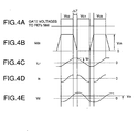
- a controller causes gate voltages VG1 and VG2 to be alternately input to the gate electrodes of the FETs 5 and 6, respectively, at the intervals of a dead time DT.
- the FETs 5 and 6 turn on alternatively.
- the transformer 9 completes the charge or the discharge of its input capacity C d1 in response to the peak value Ip of a current i Lr flowing through the resonance inductor 8.
- An AC output voltage Vd appearing on the output electrode of the transformer 9 is determined by the voltage gain of the transformer 9.
- the voltage gain of the transformer 9 varies with the variation of the switching frequency or the resistance of the load resistor 13 due to the resonance characteristic of the transformer 9. Therefore, the size of an AC voltage Vd output from the transformer 9 can be controlled by, e.g., varying the switching frequency.
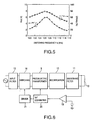
- Fig. 5 shows a DC output voltage characteristic and a power transform efficiency characteristic determined when the AC input voltage was about 100 V, the maximum DC output voltage was about 6 V, and the switching frequency was varied between 100 kHz and 115 kHz. As shown, the DC output voltage is variable over a range of from about 2 V to about 6V. Also, a power conversion efficiency of about 50 % to about 80 % is achievable.
- Fig. 6 shows an alternative embodiment of the present invention which includes control means for maintaining the DC output voltage constant without regard to the variation of a load.
- the DC voltage output from the output smoothing filter 11 is input to an error amplifier 19.
- the error amplifier 19 amplifies a voltage representative of a difference between the input DC voltage and a preselected voltage and delivers the amplified voltage to a voltage/frequency (V/F) converter 20.
- the V/F converter 20 outputs a signal whose frequency corresponds to the input voltage and feeds it to a driver 21.
- the driver 21 controls the switching frequency of the switching 16 on the basis of the frequency of the input signal.
- Fig. 7 shows that when the load current varies between 0.2 A and 1.2 A, the DC output voltage can be maintained constant at about 6 V if the switching frequency is varied between 115 kHz and 107 kHz. Also, a power transform efficiency as high as about 70 % can be maintained.
- Fig. 8 shows the second embodiment of the present invention while Fig. 10 shows an AC adapter implemented by the embodiment.
- the input smoothing capacitor 4 (generally aluminum electrolytic capacitor) is implemented as a small capacity capacitor or is omitted.
- the output smoothing capacitor 12 is implemented by a large capacity capacitor, e.g., an electric double layer capacitor 22. With this configuration, the embodiment reduces ripples.
- the electric double layer capacitor 22 can be provided with a card-like structure as thin as 1 mm to 2 mm, further miniaturizing the AC/DC converter.
- Fig. 9 is a circuit diagram showing the third embodiment of the present invention.
- a capacitor 7 is removed and instead an inductor 8 is inserted in eries with the piezoelectric transformer.
- This circuit is good when the value of cd1 is large to reduce the current Is.
- the circuit operation is almost the same as that shown in Fig. 2 .
- piezoelectric transformer operable in the longitudinal vibration mode use may be made of a piezoelectric transformer operable in any other suitable mode, e.g., a slip mode.
- a switching regulator type AC/DC converter for transforming a commercial AC power source to a DC power source includes a transformer implemented by a piezoelectric transformer formed of ceramics which is incombustible and highly isolative. This, coupled with the fact that a piezoelectric transformer can have its input electrodes and output electrodes spaced by several millimeters due to its inherent structure, eliminates the need for a barrier gap, spacer or noninflammable tape essential with a conventional electromagnetic transformer. The transformer is therefore extremely small size and contributes to the miniaturization of the entire converter.
- the piezoelectric transformer is caused to operate in the longitudinal vibration mode which maximizes the length. This allows the operation frequency to be lowered while further reducing the overall size of the transformer.
Landscapes
- Engineering & Computer Science (AREA)
- Power Engineering (AREA)
- Dc-Dc Converters (AREA)
Claims (2)
- AC/DC-Konverter vom Typ eines abschaltenden Regelers zum Umwandeln einer kommerziellen Leistungsquelle (14) in eine DC-Leistungsquelle, mit einem mittels eines piezoelektrischen Transformators (9) implementierten Transformators,
wobei der piezoelektrische Transformator (9) einen Eingangsabschnitt und einen Ausgangsabschnitt aufweist, die jeweils als Mehrzahlelektroden (18) implementiert ist, die in Längsrichtung des piezoelektrischen Transformators (9) laminiert und parallel miteinander verbunden sind, und wobei Teile zwischen der Mehrzahlelektroden (18) in der Längsrichtung polarisiert sind, wodurch der piezoelektrische Transformator (9) in einer Betriebsart mit longitudinaler Vibration betreibbar ist,
gekennzeichnet durch
einen Eingangsglättungskondensator (4) zum gleichrichten und glätten der herkömmmlichen AC-Leistungsquelle (14), der mit einer geringen Kapazität ausgestattet oder weggelassen ist, und einen Ausgangsglättungskondensator (12, 22) zum Gleichtrichten und Glätten einer von dem piezoelektrischen Transformator (9) ausgegebenen AC-Spannung hoher Frequenz, der mit einer großen Kapazität ausgestattet ist, z. B. ein elektrischer Doppelschichtkondensator, und
eine Steuereinrichtung (16) zum Steuern einer Frequenz einer AC-Spannung hoher Frequenz zum Anregen des piezoelektrischen Transformators (9), so dass eine DC-Ausgangsspannung unabhängig von einer Variation einer Last konstant bleibt. - AC/DC-Wandler vom Typ eines abschaltenden Reglers zum Konvertieren einer kommerziellen Leistungsquelle (14) in eine DC-Leistungsquelle, mit einem mittels einem piezoelektrischen Transformator (9) implementieren Transformator,
wobei der piezoelektrische Transformator (9) einen Eingangsabschnitt und einen Ausgangsabschnitt aufweist, die jeweils als Mehrzahlelektroden (18) implementiert ist, die in Richtung der Dicke des piezoelektrischen Transformators (9) laminiert und parallel miteinander verbunden sind, wobei Teile zwischen der Mehrzahlelektroden (18) in Richtung der Dicke des piezoelektrischen Transformators (9) polarisiert sind, wohingegen ein Teil zwischen dem Eingangsabschnitt und dem Ausgangsabschnitt in Längsrichtung des piezoelektrischen Transformators (9) polarisiert ist, wodurch der piezoelektrische Transformator (9) in einer Betriebsart mit transversaler Vibration betreibbar ist, um auf der Grundlage einer Vibration von Eingangselektroden in Richtung der Dicke eine Vibration in Längsrichtung anzuregen,
gekennzeichnet durch
einen Eingangsglättungskondensator (4) zum Gleichrichten und Glätten einer kommerziellen AC-Leistungsquelle (14), der mit einem geringen Kapazität ausgestattet oder weggelassen ist, und dem Ausgangsglättungskondensator (12, 22) zum Gleichtrichten und Glätten einer von dem piezoelektrischen Transformator (9) ausgegebenen AC-Spannung hoher Frequenz, der mit einer großen Kapazität ausgestattet ist, z. B. ein elektrischer Doppelschichtkondensator, und
eine Steuereinrichtung (16) zum Steuern einer Frequenz einer AC-Spannung hoher Frequenz zum Anregen des piezoelektrischen Transformators (9), so dass eine DC-Ausgangsspannung unabhängig einer Variation einer Last konstant bleibt.
Applications Claiming Priority (3)
| Application Number | Priority Date | Filing Date | Title |
|---|---|---|---|
| JP17806/97 | 1997-01-16 | ||
| JP1780697 | 1997-01-16 | ||
| JP1780697 | 1997-01-16 |
Publications (3)
| Publication Number | Publication Date |
|---|---|
| EP0854564A2 EP0854564A2 (de) | 1998-07-22 |
| EP0854564A3 EP0854564A3 (de) | 1999-09-22 |
| EP0854564B1 true EP0854564B1 (de) | 2008-03-19 |
Family
ID=11953981
Family Applications (1)
| Application Number | Title | Priority Date | Filing Date |
|---|---|---|---|
| EP98100639A Expired - Lifetime EP0854564B1 (de) | 1997-01-16 | 1998-01-15 | Wechselstrom-Gleichstromwandler mit einem piezoelektrischen Transformator |
Country Status (5)
| Country | Link |
|---|---|
| US (1) | US5969954A (de) |
| EP (1) | EP0854564B1 (de) |
| KR (1) | KR19980070528A (de) |
| DE (1) | DE69839253T2 (de) |
| TW (1) | TW356618B (de) |
Cited By (4)
| Publication number | Priority date | Publication date | Assignee | Title |
|---|---|---|---|---|
| US7558083B2 (en) | 1997-01-24 | 2009-07-07 | Synqor, Inc. | High efficiency power converter |
| US7564702B2 (en) | 1997-01-24 | 2009-07-21 | Synqor, Inc. | High efficiency power converter |
| RU2464950C2 (ru) * | 2007-06-20 | 2012-10-27 | Индиба, С.А. | Схема для радиочастотных устройств, применяемых для живых тканей, и устройство, содержащее эту схему |
| US10199950B1 (en) | 2013-07-02 | 2019-02-05 | Vlt, Inc. | Power distribution architecture with series-connected bus converter |
Families Citing this family (43)
| Publication number | Priority date | Publication date | Assignee | Title |
|---|---|---|---|---|
| TW379457B (en) * | 1997-04-18 | 2000-01-11 | Nippon Electric Co | Laminated piezo transformer |
| US6246153B1 (en) * | 1998-07-16 | 2001-06-12 | Face International Corp. | Positive feedback resonant transducer circuit |
| JP2000050696A (ja) * | 1998-08-03 | 2000-02-18 | Sawafuji Electric Co Ltd | 発動発電機用自動電圧調整装置 |
| JP3375893B2 (ja) * | 1998-08-28 | 2003-02-10 | 長野日本無線株式会社 | スイッチング電源用ドライブ回路 |
| JP3061043B2 (ja) * | 1998-12-11 | 2000-07-10 | 日本電気株式会社 | 電源回路 |
| ATE338373T1 (de) * | 1999-03-23 | 2006-09-15 | Advanced Energy Ind Inc | Gleichstromgespeistes rechnersystem mit einem hochfrequenzschaltnetzteil |
| US6694438B1 (en) * | 1999-07-02 | 2004-02-17 | Advanced Energy Industries, Inc. | System for controlling the delivery of power to DC computer components |
| DE10002326C2 (de) * | 2000-01-20 | 2003-09-25 | Infineon Technologies Ag | Schaltnetzteil |
| WO2001054208A2 (en) * | 2000-01-20 | 2001-07-26 | Koninklijke Philips Electronics N.V. | Piezoelectric transformer and assembly including such a transformer |
| DE10025028C2 (de) * | 2000-05-20 | 2002-03-28 | Josef Roediger | Elektromagnetischer Festkörper-Spannungswandler |
| US6342753B1 (en) * | 2000-09-25 | 2002-01-29 | Rockwell Technologies, Llc | Piezoelectric transformer and operating method |
| US6476542B2 (en) | 2000-12-20 | 2002-11-05 | Cts Corporation | Piezoelectric transformer with dual-phase input drive |
| EP1220435A3 (de) * | 2000-12-21 | 2003-07-09 | Alcatel | Schaltnetzteil |
| DE10135629B4 (de) | 2001-07-20 | 2005-04-21 | Infineon Technologies Ag | Schaltungsanordnung und insbesondere Schaltnetzteil |
| JP3719178B2 (ja) * | 2001-09-13 | 2005-11-24 | ソニー株式会社 | 水素ガス製造充填装置及び電気化学装置 |
| US7034800B2 (en) * | 2001-11-14 | 2006-04-25 | Matsushita Electric Industrial Co., Ltd. | Driving circuit and driving method for piezoelectric transformer, backlight apparatus, liquid crystal display apparatus, liquid crystal monitor, and liquid crystal TV |
| US20040014453A1 (en) * | 2002-07-22 | 2004-01-22 | Cashiola James P. | Name your price system and process for facilitating online acquisition of telecommunications services |
| US7653963B2 (en) * | 2002-11-12 | 2010-02-02 | Black & Decker Inc. | AC/DC hand portable wet/dry vacuum having improved portability and convenience |
| US6894460B2 (en) * | 2003-01-09 | 2005-05-17 | The Boeing Company | High efficiency passive piezo energy harvesting apparatus |
| EP1495706B1 (de) * | 2003-07-10 | 2013-05-01 | Black & Decker Inc. | Staubsauger |
| KR100631812B1 (ko) | 2004-01-07 | 2006-10-09 | 제이케이정밀전자 주식회사 | 강압용 압전변압기 및 이를 이용한 어댑터 |
| JP2006191746A (ja) * | 2005-01-06 | 2006-07-20 | Sony Corp | スイッチング電源回路 |
| KR100649508B1 (ko) * | 2005-02-02 | 2006-11-27 | 권오영 | 하이브리드 전원시스템 |
| US7510150B2 (en) * | 2005-09-28 | 2009-03-31 | The Boeing Company | Energy recovery apparatus and method |
| US7463499B2 (en) | 2005-10-31 | 2008-12-09 | Avago Technologies General Ip (Singapore) Pte Ltd. | AC-DC power converter |
| US7746677B2 (en) | 2006-03-09 | 2010-06-29 | Avago Technologies Wireless Ip (Singapore) Pte. Ltd. | AC-DC converter circuit and power supply |
| KR100887177B1 (ko) * | 2007-04-09 | 2009-03-09 | 이상범 | 전기 난로용 전력 공급 장치 |
| US7973520B2 (en) * | 2007-08-01 | 2011-07-05 | Samsung Electronics Co., Ltd. | Piezoelectric transformer type high-voltage power apparatus and image forming apparatus |
| US8549742B2 (en) * | 2007-12-19 | 2013-10-08 | Canon Kabushiki Kaisha | High-voltage power supply device and image forming apparatus having same |
| US8008836B2 (en) * | 2008-12-23 | 2011-08-30 | Newlighting Electronics Co. Ltd. | Piezoelectric phase shifter |
| JP5317884B2 (ja) * | 2009-05-22 | 2013-10-16 | 金威貿易有限公司 | 圧電式電源変換器 |
| TWI422282B (zh) * | 2009-07-24 | 2014-01-01 | Midas Wei Trading Co Ltd | A lighting device for driving a light emitting diode using an insulated piezoelectric transformer |
| US8368290B2 (en) | 2010-05-18 | 2013-02-05 | Georgia Tech Research Corporation | Rectifier-free piezoelectric energy harverster and battery charger |
| US8587972B2 (en) * | 2011-01-21 | 2013-11-19 | Qi Deng | Apparatus and system for transformer frequency control |
| CA2844139A1 (en) * | 2011-08-01 | 2013-02-07 | Gareth J. Knowles | Intrinsic adaptive and autonomic piezotransformer circuits |
| JP6008521B2 (ja) * | 2012-03-09 | 2016-10-19 | キヤノン株式会社 | 電源装置及び画像形成装置 |
| KR101372019B1 (ko) | 2012-12-18 | 2014-03-25 | 한국항공우주연구원 | 압전 변압기 제어 장치 및 방법 |
| WO2015101962A1 (en) * | 2014-01-06 | 2015-07-09 | Koninklijke Philips N.V. | Application of piezo technology to convert alternating current (ac) line power to isolated direct current (dc) power in high external magnetic fields |
| WO2017001184A1 (en) * | 2015-06-30 | 2017-01-05 | Danmarks Tekniske Universitet | Resonant power converter comprising adaptive dead-time control |
| EP3229359A1 (de) * | 2016-04-06 | 2017-10-11 | Neumüller Elektronik GmbH | Resonanzwandler und leistungsvorrichtung mit solch einem wandler |
| JP7003445B2 (ja) * | 2017-05-19 | 2022-02-04 | オムロン株式会社 | 非接触給電装置 |
| JP6399244B1 (ja) * | 2017-06-02 | 2018-10-03 | オムロン株式会社 | 非接触給電装置及び異常停止方法 |
| JP6958701B1 (ja) * | 2020-09-28 | 2021-11-02 | 富士電機株式会社 | 電力変換装置 |
Family Cites Families (20)
| Publication number | Priority date | Publication date | Assignee | Title |
|---|---|---|---|---|
| US3700936A (en) * | 1969-09-30 | 1972-10-24 | Denki Onkyo Co Ltd | High voltage generating apparatus |
| US4392074A (en) * | 1980-09-19 | 1983-07-05 | Siemens Aktiengesellschaft | Trigger device and piezo-ignition coupler with galvanic decoupling |
| JPS5879778A (ja) * | 1981-11-05 | 1983-05-13 | Nec Corp | 圧電磁器トランスフイルタ |
| CH658960A5 (de) * | 1982-11-30 | 1986-12-15 | Landis & Gyr Ag | Transformatorlose stromversorgungsschaltung. |
| JPS61152165A (ja) * | 1984-12-26 | 1986-07-10 | Hitachi Ltd | 圧電トランス使用直流高圧発生装置 |
| JPS63200579A (ja) * | 1987-02-16 | 1988-08-18 | Ngk Spark Plug Co Ltd | 圧電トランス |
| JPH03285572A (ja) * | 1990-03-30 | 1991-12-16 | Nec Corp | スイッチング電源回路 |
| JP3064458B2 (ja) * | 1991-04-02 | 2000-07-12 | 日本電気株式会社 | 厚み縦振動圧電磁器トランスとその駆動方法 |
| JPH05160460A (ja) * | 1991-12-05 | 1993-06-25 | Fujitsu Ltd | 圧電トランス |
| US5548189A (en) * | 1992-03-26 | 1996-08-20 | Linear Technology Corp. | Fluorescent-lamp excitation circuit using a piezoelectric acoustic transformer and methods for using same |
| JP2591423B2 (ja) * | 1992-07-17 | 1997-03-19 | 日本電気株式会社 | 電力用圧電トランスコンバータ |
| JPH06245548A (ja) * | 1993-02-22 | 1994-09-02 | Daishinku Co | インバータ回路 |
| JP2518527B2 (ja) * | 1993-07-20 | 1996-07-24 | 日本電気株式会社 | 圧電トランスコンバ―タ |
| DE4334592C1 (de) * | 1993-10-11 | 1994-07-21 | Siemens Ag | Hochfrequenz-Generator |
| JP2606667B2 (ja) * | 1994-07-22 | 1997-05-07 | 日本電気株式会社 | 圧電磁器トランス及びその駆動方法 |
| JP2725603B2 (ja) * | 1994-07-26 | 1998-03-11 | 日本電気株式会社 | 圧電磁器トランスとその駆動方法 |
| JP2751842B2 (ja) * | 1994-10-05 | 1998-05-18 | 日本電気株式会社 | 圧電トランスの駆動回路および駆動方法 |
| JP2730506B2 (ja) * | 1995-02-27 | 1998-03-25 | 日本電気株式会社 | 圧電トランスを用いたdc/dcコンバータ |
| JP3119154B2 (ja) * | 1995-07-06 | 2000-12-18 | 日立金属株式会社 | 圧電トランス及びそれを用いた電力変換装置 |
| JP2778554B2 (ja) * | 1995-10-12 | 1998-07-23 | 日本電気株式会社 | 圧電トランス駆動回路 |
-
1998
- 1998-01-07 TW TW087100147A patent/TW356618B/zh active
- 1998-01-15 US US09/007,571 patent/US5969954A/en not_active Expired - Fee Related
- 1998-01-15 EP EP98100639A patent/EP0854564B1/de not_active Expired - Lifetime
- 1998-01-15 KR KR1019980000990A patent/KR19980070528A/ko not_active Ceased
- 1998-01-15 DE DE69839253T patent/DE69839253T2/de not_active Expired - Fee Related
Cited By (12)
| Publication number | Priority date | Publication date | Assignee | Title |
|---|---|---|---|---|
| US7558083B2 (en) | 1997-01-24 | 2009-07-07 | Synqor, Inc. | High efficiency power converter |
| US7564702B2 (en) | 1997-01-24 | 2009-07-21 | Synqor, Inc. | High efficiency power converter |
| US8023290B2 (en) | 1997-01-24 | 2011-09-20 | Synqor, Inc. | High efficiency power converter |
| US8493751B2 (en) | 1997-01-24 | 2013-07-23 | Synqor, Inc. | High efficiency power converter |
| US9143042B2 (en) | 1997-01-24 | 2015-09-22 | Synqor, Inc. | High efficiency power converter |
| RU2464950C2 (ru) * | 2007-06-20 | 2012-10-27 | Индиба, С.А. | Схема для радиочастотных устройств, применяемых для живых тканей, и устройство, содержащее эту схему |
| US8465483B2 (en) | 2007-06-20 | 2013-06-18 | Indiba, S.A. | Circuit for radiofrequency devices applicable to living tissues and device containing same |
| US10199950B1 (en) | 2013-07-02 | 2019-02-05 | Vlt, Inc. | Power distribution architecture with series-connected bus converter |
| US10594223B1 (en) | 2013-07-02 | 2020-03-17 | Vlt, Inc. | Power distribution architecture with series-connected bus converter |
| US11075583B1 (en) | 2013-07-02 | 2021-07-27 | Vicor Corporation | Power distribution architecture with series-connected bus converter |
| US11705820B2 (en) | 2013-07-02 | 2023-07-18 | Vicor Corporation | Power distribution architecture with series-connected bus converter |
| US12395087B1 (en) | 2013-07-02 | 2025-08-19 | Vicor Corporation | Power distribution architecture with series-connected bus converter |
Also Published As
| Publication number | Publication date |
|---|---|
| DE69839253D1 (de) | 2008-04-30 |
| EP0854564A3 (de) | 1999-09-22 |
| US5969954A (en) | 1999-10-19 |
| KR19980070528A (ko) | 1998-10-26 |
| EP0854564A2 (de) | 1998-07-22 |
| DE69839253T2 (de) | 2009-04-30 |
| TW356618B (en) | 1999-04-21 |
Similar Documents
| Publication | Publication Date | Title |
|---|---|---|
| US5969954A (en) | AC/DC converter with a piezoelectric transformer | |
| EP0665600B1 (de) | Gerät zum Steuern einer Entladungslampe und piezoelektrischer Wandler dafür | |
| KR100241210B1 (ko) | 압전변압기 및 그것을 사용한 전력변환장치 | |
| US6738267B1 (en) | Switched power supply converter with a piezoelectric transformer | |
| US6433458B2 (en) | Method and unit for driving piezoelectric transformer used for controlling luminance of cold-cathode tube | |
| JP2011512778A (ja) | 共振コンバータにおける整合負荷のエミュレーション | |
| JP2002017090A (ja) | 圧電トランスの駆動方法および駆動装置 | |
| JPH10262369A (ja) | 圧電トランスを用いたac/dcコンバータ | |
| JPH0869890A (ja) | 積層一体型圧電トランス及びそれを用いた放電管の駆動装置 | |
| WO2022153911A1 (ja) | 共振電源回路 | |
| Hamamura et al. | New control method of piezoelectric transformer converter by PWM and PFM for wide range of input voltage | |
| JP3452745B2 (ja) | スイッチング電源 | |
| JP6865985B1 (ja) | 共振絶縁形dc−dcコンバータ | |
| JP3037903B2 (ja) | 圧電トランス式電力変換装置及びその駆動方法 | |
| JP2001275343A (ja) | 圧電トランス、圧電トランスの駆動回路、圧電トランスの駆動方法及び、圧電トランスを用いた冷陰極管駆動装置 | |
| JP2738354B2 (ja) | 広入力圧電トランスコンバータ | |
| Hamamura et al. | Piezoelectric transformer AC-DC converter over a worldwide range of input voltage by combined PWM and PFM control | |
| JPH09148645A (ja) | 圧電トランス式電力変換器 | |
| JP2000102246A (ja) | 圧電トランスを用いたac−dcコンバータ回路 | |
| JP3580492B2 (ja) | 積層型圧電トランス及びそれを用いた電力変換装置 | |
| JPH0993959A (ja) | インバ−タ装置 | |
| JPH10135529A (ja) | 圧電トランスの駆動回路 | |
| JPH10174436A (ja) | 圧電素子駆動回路 | |
| JPH08340680A (ja) | 電力変換装置 | |
| JP2002281756A (ja) | スイッチングコンバータ回路 |
Legal Events
| Date | Code | Title | Description |
|---|---|---|---|
| PUAI | Public reference made under article 153(3) epc to a published international application that has entered the european phase |
Free format text: ORIGINAL CODE: 0009012 |
|
| AK | Designated contracting states |
Kind code of ref document: A2 Designated state(s): DE FR GB |
|
| AX | Request for extension of the european patent |
Free format text: AL;LT;LV;MK;RO;SI |
|
| PUAL | Search report despatched |
Free format text: ORIGINAL CODE: 0009013 |
|
| AK | Designated contracting states |
Kind code of ref document: A3 Designated state(s): AT BE CH DE DK ES FI FR GB GR IE IT LI LU MC NL PT SE |
|
| AX | Request for extension of the european patent |
Free format text: AL;LT;LV;MK;RO;SI |
|
| RIC1 | Information provided on ipc code assigned before grant |
Free format text: 6H 02M 3/28 A, 6H 01L 41/107 B |
|
| 17P | Request for examination filed |
Effective date: 19990819 |
|
| AKX | Designation fees paid |
Free format text: DE FR GB |
|
| 17Q | First examination report despatched |
Effective date: 20061116 |
|
| GRAP | Despatch of communication of intention to grant a patent |
Free format text: ORIGINAL CODE: EPIDOSNIGR1 |
|
| GRAS | Grant fee paid |
Free format text: ORIGINAL CODE: EPIDOSNIGR3 |
|
| GRAA | (expected) grant |
Free format text: ORIGINAL CODE: 0009210 |
|
| AK | Designated contracting states |
Kind code of ref document: B1 Designated state(s): DE FR GB |
|
| REG | Reference to a national code |
Ref country code: GB Ref legal event code: FG4D |
|
| REF | Corresponds to: |
Ref document number: 69839253 Country of ref document: DE Date of ref document: 20080430 Kind code of ref document: P |
|
| ET | Fr: translation filed | ||
| PLBE | No opposition filed within time limit |
Free format text: ORIGINAL CODE: 0009261 |
|
| STAA | Information on the status of an ep patent application or granted ep patent |
Free format text: STATUS: NO OPPOSITION FILED WITHIN TIME LIMIT |
|
| 26N | No opposition filed |
Effective date: 20081222 |
|
| PGFP | Annual fee paid to national office [announced via postgrant information from national office to epo] |
Ref country code: DE Payment date: 20090108 Year of fee payment: 12 |
|
| PGFP | Annual fee paid to national office [announced via postgrant information from national office to epo] |
Ref country code: GB Payment date: 20090114 Year of fee payment: 12 |
|
| PGFP | Annual fee paid to national office [announced via postgrant information from national office to epo] |
Ref country code: FR Payment date: 20090113 Year of fee payment: 12 |
|
| GBPC | Gb: european patent ceased through non-payment of renewal fee |
Effective date: 20100115 |
|
| REG | Reference to a national code |
Ref country code: FR Ref legal event code: ST Effective date: 20100930 |
|
| PG25 | Lapsed in a contracting state [announced via postgrant information from national office to epo] |
Ref country code: FR Free format text: LAPSE BECAUSE OF NON-PAYMENT OF DUE FEES Effective date: 20100201 |
|
| PG25 | Lapsed in a contracting state [announced via postgrant information from national office to epo] |
Ref country code: DE Free format text: LAPSE BECAUSE OF NON-PAYMENT OF DUE FEES Effective date: 20100803 |
|
| PG25 | Lapsed in a contracting state [announced via postgrant information from national office to epo] |
Ref country code: GB Free format text: LAPSE BECAUSE OF NON-PAYMENT OF DUE FEES Effective date: 20100115 |