EP0854590B1 - Processeur analogique pour satellites numériques - Google Patents
Processeur analogique pour satellites numériques Download PDFInfo
- Publication number
- EP0854590B1 EP0854590B1 EP97117417A EP97117417A EP0854590B1 EP 0854590 B1 EP0854590 B1 EP 0854590B1 EP 97117417 A EP97117417 A EP 97117417A EP 97117417 A EP97117417 A EP 97117417A EP 0854590 B1 EP0854590 B1 EP 0854590B1
- Authority
- EP
- European Patent Office
- Prior art keywords
- digital
- sub
- beams
- digital satellite
- band processing
- Prior art date
- Legal status (The legal status is an assumption and is not a legal conclusion. Google has not performed a legal analysis and makes no representation as to the accuracy of the status listed.)
- Expired - Lifetime
Links
- 238000012545 processing Methods 0.000 claims description 72
- 239000011159 matrix material Substances 0.000 claims description 21
- 238000001914 filtration Methods 0.000 claims description 7
- 238000010897 surface acoustic wave method Methods 0.000 claims description 4
- 238000013461 design Methods 0.000 description 14
- 238000005516 engineering process Methods 0.000 description 11
- 238000000034 method Methods 0.000 description 10
- 239000000969 carrier Substances 0.000 description 9
- 238000004891 communication Methods 0.000 description 9
- 230000008901 benefit Effects 0.000 description 7
- 230000008569 process Effects 0.000 description 7
- 238000001228 spectrum Methods 0.000 description 5
- 238000006243 chemical reaction Methods 0.000 description 4
- 238000010586 diagram Methods 0.000 description 4
- 230000001172 regenerating effect Effects 0.000 description 4
- 238000013519 translation Methods 0.000 description 4
- 230000003321 amplification Effects 0.000 description 2
- 230000008859 change Effects 0.000 description 2
- 239000002131 composite material Substances 0.000 description 2
- 238000012986 modification Methods 0.000 description 2
- 230000004048 modification Effects 0.000 description 2
- 238000003199 nucleic acid amplification method Methods 0.000 description 2
- 239000000047 product Substances 0.000 description 2
- 230000004044 response Effects 0.000 description 2
- 230000007704 transition Effects 0.000 description 2
- 229910001218 Gallium arsenide Inorganic materials 0.000 description 1
- 239000006227 byproduct Substances 0.000 description 1
- 230000015556 catabolic process Effects 0.000 description 1
- 238000005352 clarification Methods 0.000 description 1
- 238000000354 decomposition reaction Methods 0.000 description 1
- 238000006731 degradation reaction Methods 0.000 description 1
- 230000001419 dependent effect Effects 0.000 description 1
- 230000002452 interceptive effect Effects 0.000 description 1
- 230000007246 mechanism Effects 0.000 description 1
- 238000005457 optimization Methods 0.000 description 1
- 230000008672 reprogramming Effects 0.000 description 1
- 238000005070 sampling Methods 0.000 description 1
- 230000003595 spectral effect Effects 0.000 description 1
Images


Classifications
-
- H—ELECTRICITY
- H04—ELECTRIC COMMUNICATION TECHNIQUE
- H04B—TRANSMISSION
- H04B7/00—Radio transmission systems, i.e. using radiation field
- H04B7/14—Relay systems
- H04B7/15—Active relay systems
- H04B7/185—Space-based or airborne stations; Stations for satellite systems
- H04B7/1851—Systems using a satellite or space-based relay
- H04B7/18515—Transmission equipment in satellites or space-based relays
-
- Y—GENERAL TAGGING OF NEW TECHNOLOGICAL DEVELOPMENTS; GENERAL TAGGING OF CROSS-SECTIONAL TECHNOLOGIES SPANNING OVER SEVERAL SECTIONS OF THE IPC; TECHNICAL SUBJECTS COVERED BY FORMER USPC CROSS-REFERENCE ART COLLECTIONS [XRACs] AND DIGESTS
- Y02—TECHNOLOGIES OR APPLICATIONS FOR MITIGATION OR ADAPTATION AGAINST CLIMATE CHANGE
- Y02D—CLIMATE CHANGE MITIGATION TECHNOLOGIES IN INFORMATION AND COMMUNICATION TECHNOLOGIES [ICT], I.E. INFORMATION AND COMMUNICATION TECHNOLOGIES AIMING AT THE REDUCTION OF THEIR OWN ENERGY USE
- Y02D30/00—Reducing energy consumption in communication networks
- Y02D30/70—Reducing energy consumption in communication networks in wireless communication networks
Definitions
- the present invention is directed toward the field of multi-beam communication satellites that incorporate on-board digital processors.
- it relates to a digital satellite having an analog pre-processor according to the preamble of claim 1.
- the analog pre-processor is connected between the satellite's receive circuitry and the on-board digital processor(s) in order to optimize the processing capability of the satellite, and to provide the ability to manage the risk of selecting a particular digital processor technology.
- Communication satellites generally consist of a payload and a bus.
- the bus includes the satellite structure (or platform), electrical power system, thermal control system, propulsion system, and orbit control system.
- the payload which is the communications part of the satellite, generally includes the antenna (receive and transmit) subsystem, the repeater, and a telemetry, tracking and command module.
- the present invention relates to improvements in the communications satellite payload, in particular the repeater section of a digital satellite.
- a transparent repeater also known as a "bent pipe” repeater, performs filtering, frequency and power conversion, and switching between beams without altering the baseband signal in any manner.
- this filtering and switching is performed by analog means.
- For smaller bandwidth carriers it is possible to perform some of the repeater functions digitally, such as the filtering and switching steps.
- a regenerative repeater processes the baseband signal content of the RF uplink signal such that the individual carrier signals of an uplink beam are demodulated (i.e. the information bits of the signal are recovered).
- a regenerative repeater can also switch the demodulated data to an arbitrary output beam and time multiplex (as in a TDM system) the switched signals from all beams on to one or a few downlink carriers using an optimized remodulation and/or multiple access scheme, thus resulting in a more efficient system.
- Transparent repeaters are generally (but not always) analog systems, whereas regenerative repeaters generally employ on-board digital processors.
- the risk associated with selecting a particular digital processor is determined by the bandwidth to be processed. For example, a lower power processor capable of processing 25 MHz of bandwidth that incorporates standard space-qualified hardware is much less risky to employ than a higher power 200 MHz processor that may include components and elements that have not been previously proven in space.
- each uplink beam (1-N) is shown connected to an individual receive element 10 of an antenna.
- multiple uplink beams could be connected to each receive element 10 in a process known as beamforming.
- a receiver 12 is connected to the receive element 10 and receives signals covering a certain bandwidth of a given beam from an associated antenna by filtering the desired bandwidth to remove unwanted out-of-band signals and noise, and downconverting to a common intermediate frequency for all beams.
- This entire bandwidth is routed to mixer 16, where the received RF signal is downconverted to a baseband signal by mixing with a fixed signal from a local oscillator 14.
- the baseband signal is filtered by an Image Rejection Filter (IRF) 18, which is a low pass filter that eliminates the higher frequency image that is a byproduct of the frequency downconversion process.
- IRF Image Rejection Filter
- All of the carrier signals that comprise the beam are routed to one of N digital processors 20 which perform analog to digital conversion and other digital processing, such as demodulation, switching, etc.
- the well-known elements of the repeater that are used to transmit downlink beams back to the earth, or to another satellite in the case of an inter-satellite link, are not shown in Figure 1 (or the rest of the figures in this application) for clarity. These elements include remodulation or digital remultiplexing circuitry, upconversion mixers for converting the processed baseband signals to an appropriate downlink frequency, high power amplifiers (HPA) for boosting the power of the upconverted signal, multiplexing where required, and the multiple spot-beam transmit antennas. Also not explicitly shown is the digital switch that is generally connected between the outputs of the digital processors and the downlink circuitry.
- N digital processors are required.
- Each digital processor must be capable of handling the full-bandwidth (up to 125 MHz in the recently proposed systems) of an incoming uplink beam in order to provide flexibility for changing traffic patterns.
- Presently available space-qualified low-power digital technology cannot handle this bandwidth.
- a digital satellite repeater that includes an analog pre-processor for switching, extracting and routing sub-bands of incoming uplink beams in order to optimize available on-board digital processing capabilities.
- an analog pre-processor that has the capability to adapt to changes in the traffic pattern by changing the way it switches and routes incoming beams, and by changing the portion (sub-band) of the incoming beam bandwidth that is extracted.
- a digital satellite repeater that has an architecture which can provide for implementation of any kind of redundancy scheme, at minimal hardware cost.
- Such a repeater could easily accommodate standard 2:1 or 3:2 types of redundancy, as well as unconventional schemes such as 10:8 or 12:8.
- These unconventional schemes, such as 12:8 have higher reliability than, for example, four 3:2 conventional redundancy blocks, even though the amount of hardware is the same.
- US-A-4 931 802 discloses a digital satellite according to the preamble of claim 1.
- a multi-stage switching satellite repeater having a first outer stage for switching on the uplink side of the satellite, a group of demodulators, a digital baseband processor that performs a second switching function, a group of demodulators, and a second outer stage for switching on the downlink side of the satellite.
- the sub-channel switching architecture includes an input multiplexer, a set of filter banks for extracting sub-channels from incoming beams of information, a sub-channel switching matrix, and a combining circuitry for combining the switched sub-channels back into downlink beams.
- It is the object of the present invention to provide a digital satellite comprising a digital satellite repeater that incorporates an analog pre-processor for switching, extracting and routing sub-bands from a plurality of incoming beams to a plurality of digital baseband processors.
- a digital satellite having at least one receive antenna for receiving uplink beams, a plurality of digital processors for processing the uplink beams, and an analog processor
- the analog processor comprises: at least one switching matrix connected to the at least one receive antenna; and, a plurality of sub-band processing chains connected between the outputs of the at least one switching matrix and the plurality of digital processors, characterized in that the at least one switching matrix is reconfigurable for routing the uplink beams to a required number of sub-band processing chains and the digital processors, and each of the plurality of sub-band processing chains comprises a frequency translator and segments one of the uplink beams by translating the frequency of the uplink beam to form at least one translated signal and filtering the at least one translated signal to form at least one sub-band signal.
- the analog processor enables the digital processing power of the satellite to be optimized to the incoming traffic pattern of the uplink beams. If a certain beam is underutilized, then only spectral segments containing signals are extracted and routed for digital processing. The unused portion of the incoming beam is not processed.
- Some of the sub-band segments may only be partially occupied if the bandpass filter bandwidths do not fit evenly into the utilized spectrum (e.g. in a 125 MHz beam, if 40 MHz is occupied and the sub-band processing chains have 25 MHz bandpass filters, then 2 sub-band processing chains are required for the beam, resulting in a full 25 MHz segment from one filter and a partially occupied 15 MHz segment from the second filter). Although in this case there is 10 MHz of wasted digital processing power (assuming 25 MHz digital processors), the design tradeoff is between optimum digital processing and extra filters required for increased bandwidth granularity (i.e. more filters with smaller bandwidths).
- the analog processor provides for a programmable one-to-K correspondence, where K could be one for underutilized beams, but in general will be greater than one for partially or fully utilized uplink beams. For example, if a given uplink beam is fully utilized at 125 MHz, and the satellite includes a plurality of 25 MHz digital processors, then the analog processor is programmed to switch the uplink beam to 5 sub-band processing chains, and segments and routes the five 25 MHz sub-bands for digital processing. If the traffic pattern on this beam is then changed for some reason such that only 75 MHz of information was being transmitted, the analog processor could be reprogrammed to switch the beam to only 3 sub-band processing chains. In this manner, the analog processor is adaptable to changing traffic patterns, thus providing for continued optimization of the on-board digital processing power over the life of the satellite. This is a major advantage over conventional digital processing repeaters.
- a "pool" of digital processors can be shared among multiple uplink beams, shifting the processing power among the beams as required by shifting beam utilization or traffic patterns.
- An additional advantage of the disclosed architecture is that any type of redundancy scheme can be implemented by simply adding downconversion or sub-band processing chains and reprogramming the included switching matrix to route the incoming beam to the appropriate redundant chain(s).
- the analog processor also enables the use of lower-power, proven digital processing technology.
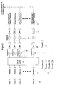
- Figure 2 sets forth a block diagram of an analog pre-processor in a digital satellite according to the present invention incorporated into a digital satellite repeater.
- the downlink circuitry of the present invention including remodulation, upconversion, high power amplification (HPA), and the multi-beam transmit antennas are omitted from the drawings for clarification.
- the digital switch that is generally connected between the digital processors 20 and the downlink circuitry is not shown.
- Figure 2 includes some of the same elements as the prior art one-to-one digital regenerative repeater, including at least one antenna having a plurality receive elements 10 for receiving beams of information, labelled Beam 1 to Beam N.
- Figure 2 shows all N incoming uplink beams being routed through a single analog pre-processor.
- These N beams form a "group" of beams.
- a group may consist of anywhere from one to all of the beams of a particular multibeam configuration.
- several groups of beams could be formed, and in this case each group of beams would have an associated analog pre-processor for the group.
- the use of multiple analog pre-processors with a group of beams assigned to each analog processor. Grouping of beams in this manner for switching significantly reduces the size of the switching matrix 22, although at the expense of interbeam connectivity and flexibility.
- Figure 2 shows a single receive element 10 and uplink beam per receiver 12, although, alternatively, a beam can be formed from a combination of receive elements 10 from a given antenna. This is done using multiple receive elements, the angular offset of the particular elements setting the direction of the beam.
- the multiple receive elements 10 of the given antenna are then connected to the inputs of a beamformer to form a composite signal.
- a beamformer is a device which modifies the characteristics of the signals from the receiver elements, in some fashion, in order to provide a composite signal with more desirable characteristics.
- a vector product of adjacent beams is performed in the beamformer to obtain characteristics such as lower sidelobes or wider coverage area. This technique is known as beamforming.
- the beamformer is preferably positioned between several of the receive elements 10 and a receiver 12.
- beams may be formed by a phased array antenna.
- the antenna has a set of discrete receive or transmit elements on a fixed grid, which is generally rectangular or hexagonal.
- the beams are pointed or directed by phase shifting the outputs of each individual element appropriately so that only signals received from the desired direction add coherently. This is done by performing a complex vector dot product, either analog or digital, between the received signals and the desired direction vector to form a set of beamformer outputs. This is also known as beamforming.
- each receiver 12 generally consists of low noise amplification (LNA) stages, followed by a downconversion stage to a frequency that is compatible with the NxM Switching Matrix 22.
- LNA low noise amplification
- the beamforming can be performed after the LNAs and before the downconverters of the receiver circuits 12, or could be done after both the LNAs and downconverters.
- the RF signal in each uplink beam consists of a number of "carriers". Optimally, the carriers in each beam are contiguous in order to minimize the number of sub-band processing chains required.
- the signals from the N receiver circuits 12 are routed to the inputs of an NxM switching matrix 22, which preferably has a cross-bar switch architecture implemented with microwave switches, but could alternatively be any other type of switching matrix architecture, and could be implemented with other switching technologies, such as a solid-state GaAs switches, or waveguide switches.
- any input can be routed to any of the M outputs, but each of the M outputs can only be connected to one input.
- the switch matrix 22 is configured, and can be reconfigured, to route the incoming beams to the required number of sub-band processing chains 28, 30 depending on the number of carriers (i.e. the bandwidth) of the incoming uplink signal to be processed.
- Each sub-band processing chain consists of a downconverter or mixer 30, a variable local oscillator (VLO) 26, and a band pass filter (BPF) 28.
- the mixer 30 takes as inputs one of the uplink beams from the NxM switch and a selectable frequency translation signal from a variable local oscillator 26.
- the frequency translation signal from the VLO 26 is preferably generated by the analog pre-processor, but could be from an external source, or could be selected from a set of fixed local oscillators, supplied either internally or externally to the analog pre-processor.
- the sub-band processing chains extract or segment a portion of the incoming RF uplink spectrum.
- the frequency translation signal from the VLO 26 must be selectable or programmable over the bandwidth of the incoming RF signals.
- the frequency of the VLO 26 is selected in order to bring the desired carriers (sub-band) into the passband of the subsequent bandpass filters 28.
- This method permits the same type of filters 28, with the same center frequency and bandwidth response, to be used for all of the BPF's. This is not a requirement however, as any type of BPF can be used, including filters having different center frequencies and bandwidths. For example, several smaller bandwidth chains may be included to handle known low utilization beams with higher bandwidth chains for projected high utilization beams.
- the bandpass filters 28 are preferably surface-acoustic wave (SAW) devices, and also function as anti-aliasing filters (AAF) for subsequent digitization.
- SAW surface-acoustic wave
- AAF anti-aliasing filters
- a SAW filter is preferable in this situation because of its linear phase characteristics (very low signal degradation) and very narrow transition region. The narrow transition region allows a minimum sampling rate to be used, thus reducing the required digital processing.
- an anti-aliasing filtering operation is carried out to prevent out-of-band energy from being folded into the band of interest and thus interfering with the signal of interest. This is done so that the digitization can be performed either at an intermediate frequency, or baseband.
- the sub-band After passing the extracted or segmented sub-band through the bandpass filters 28, the sub-band is downconverted to baseband using a mixer 16 and fixed local oscillator 14, and passed through the image rejection filter (IRF) 18.
- the baseband sub-band signal is then converted to digital and processed by a digital processor 20, which may perform demodulation and digital switching of the baseband signals.
- Figure 2 shows a real downconversion to baseband
- the repeater could alternatively employ a complex (I/Q) decomposition and downconversion.
- downconversion to baseband is shown, alternatively, downconversion to an intermediate frequency by mixer 16 could be carried out followed by an intermediate frequency analog-to-digital conversion.
- the analog pre-processor can be used to manage and optimize the risk of choosing a particular digital processor technology.
- a hypothetical 8-beam digital satellite having at least one antenna with a plurality of receive elements 10 for receiving the uplink beams.
- Each beam may include up to 125 MHz of information spread over a number of carriers.
- 2 of the uplink beams will be completely utilized (125 MHz), 2 of the beams will be only partially utilized (75 MHz typically), and the remaining 4 beams will be generally underutilized (25 MHz average).
- a standard 2:1 redundancy scheme would require a doubling of the hardware in order to provide a redundant path for each processor. This would be very costly in terms of space, power, and mass, and would thus drive up the cost of the satellite.
- an architecture can be provided which optimizes the selection of digital hardware and thereby manages the risk of using a particular technology. Assuming the same situation as above, the level of risk viewed as acceptable is determined, and the hardware is accordingly selected. For example, assuming a minimum risk design, 25 MHz low-power, space-qualified digital processors are utilized. Knowing that the typical overall satellite bandwidth to be processed is 500 MHz, at least 20 sub-band processing chains and associated digital processors are selected. To be on the safe side, several additional chains are added in order to deal with additional traffic, or with a potentially expanding traffic pattern. In this manner, the design is selected to match the level of risk deemed acceptable.
- the NxM switching matrix 22 is configured to route the incoming beams to the appropriate number of sub-band processing chains.
- the two fully utilized beams (125 MHz) are routed to five sub-band processing chains, each connected to a 25 MHz digital processor 20.
- the partially utilized beams (75 Mhz) are routed to three sub-band processing chains, and the underutilized beams (25 MHz) are routed to one sub-band processing chain.
- This connectivity can be changed over the lifetime of the satellite as general traffic patterns change, or even on an hourly basis for daily traffic fluctuations, e.g. during business hours.
- Each sub-band that contains carriers of interest is then extracted or segmented from the total bandwidth of the uplink beam by selecting the frequency of the variable local oscillator 26 to bring the sub-band within the passband of the BPF 28.
- the passband of the BPFs is at least 25 MHz in order to accommodate the maximum sub-band; but as stated above, could be designed to be narrower in order to provide finer granularity for certain underutilized beams.
- the total digital processing power of the satellite is matched or optimized based on the incoming traffic pattern of the uplink beams.
- the satellite can be re-optimized by reconfiguring the NxM switch matrix 22 and re-selecting the translation frequency of the VLOs 26.
- a higher risk design may be acceptable, using digital processors capable of processing a larger bandwidth than 25 MHz, such as 75 MHz processors. Assuming again a 500 MHz total traffic pattern as described above and 75 MHz digital processors, the design of the analog pre-processor is again optimized by matching the processing capability to the projected traffic pattern.
- the two fully utilized beams (125 MHz) are each routed to two sub-band processing chains and two 75 MHz processors, the partially utilized beams (75 Mhz) are routed to one sub-band processing chain, and the underutilized beams are each routed to one sub-band processing chain.
- the passband of the BPFs 28 are increased to accommodate the maximum 75 MHz sub-band
- the NxM switch matrix 22 is configured to appropriately route the incoming uplink signals to the sub-band processing chains
- the selectable VLOs 26 are programmed to extract the appropriate segments or sub-bands of the overall uplink beam bandwidth.
- the analog pre-processor is used to optimize the amount of digital hardware required.
- the analog pre-processor provides for a programmable optimized design that can be re-optimized based on changing traffic patterns, and which can flexibly accommodate various redundancy schemes with minimal hardware impact.
- a satellite having the aforementioned arrangement includes the added advantage of being able to support any type of redundancy scheme by simply adding sub-band processing chains.
- a conventional 2:1 redundancy scheme can be designed by adding an additional 20 sub-band processing chains.
- other, non-conventional redundancy schemes such as 10:8 or 12:8 as these schemes minimize the total amount of additional hardware to achieve a given level of redundancy.
- redundancy schemes are facilitated by adding sub-band processing chains and configuring the switch matrix. Since the switch matrix 22 can switch any beam to any sub-band chain, a failure of any sub-band processing chain or any digital processor can be overcome by rerouting that beam to one of the redundant chains. Thus a high level of reliability can be achieved while minimizing the increase in hardware.
- FIG. 3 an alternative embodiment of the present invention is set forth.
- the satellite repeater of Figure 3 is identical to that of Figure 2, except that after the sub-band processing chains but before the downconversion to baseband circuitry, a summer or combiner circuit 24 is used to combine the sub-bands from several sub-band processing chains.
- This architecture uses higher-risk digital processing technology, but retains the advantages in being able to optimize the processing power to a potentially changing traffic pattern, and also retains the advantages of flexibility, programmability, and redundancy.
- bandpass filters BPFs 28 must have adjacent and non-overlapping center frequencies and bandwidths so that when combined the bandwidth out of the summer 24 is equal to the sum of the bandwidths of the individual BPFs 28.
- the system of figure 3 can be optimized to segment, route, combine and process the uplink signals.
- each bandpass filter 28 in a group of five will have a different center frequency and may have different bandwidths, although for this example the assumption is that all BPFs have a 25 MHz passband.
- the combination of the five sub-band extracted signals is combined by the summer 24 and subsequently downconverted to baseband for digital processing.
- the processing power of the satellite can be optimized for a higher-risk digital processing technology, while maintaining the granularity of a lower-risk processor system.
- the system of Figure 3 digitally processes 125 MHz combined sub-bands, but has the ability to switch, segment and route much smaller 25 MHz sub-bands. Such a combination of functionality is not possible with prior art digital satellite repeaters.
Landscapes
- Engineering & Computer Science (AREA)
- Physics & Mathematics (AREA)
- Astronomy & Astrophysics (AREA)
- Aviation & Aerospace Engineering (AREA)
- General Physics & Mathematics (AREA)
- Computer Networks & Wireless Communication (AREA)
- Signal Processing (AREA)
- Radio Relay Systems (AREA)
Claims (13)
- Satellite numérique ayant au moins une antenne de réception (10) pour recevoir des faisceaux de liaison montante, une pluralité de processeurs numériques (20) pour traiter les faisceaux de liaison montante, et un processeur analogique, dans lequel le processeur analogique comprend :au moins une matrice de commutation (22) connectée à l'au moins une antenne de réception (10) ; etune pluralité de chaînes de traitement de sous-bandes (14, 16, 26, 28, 30) connectées entre les sorties de l'au moins une matrice de commutation (22) et la pluralité de processeurs numériques (20).caractérisé en ce que l'au moins une matrice de commutation (22) est reconfigurable pour router les faisceaux de liaison montante vers un nombre requis de chaînes de traitement de sous-bandes (14, 16, 26, 28, 30) et les processeurs numériques (20), et chacune de la pluralité de chaînes de traitement de sous-bandes (14, 16, 26, 28, 30) comprend un transposeur de fréquence (30) et segmente l'un des faisceaux de liaison montante en transposant la fréquence du faisceau de liaison montante afin de former au moins un signal transposé et filtrer l'au moins un signal transposé afin de former au moins un signal de sous-bande.
- Satellite numérique selon la revendication 1, dans lequel l'au moins une matrice de commutation (22) est reconfigurable pour router les faisceaux de liaison montante vers un nombre optimisé de chaînes de traitement de sous-bandes (14, 16, 26, 28, 30) et les processeurs numériques, et la pluralité de chaînes de traitement de sous-bandes (14, 16, 26, 28, 30) transposent chacune la fréquence du faisceau de liaison montante et filtre celui-ci pour fournir l'au moins un faisceau des faisceaux de liaison montante à un nombre optimisé de processeurs numériques (20).
- Satellite numérique selon la revendication 1 ou 2, dans lequel les chaînes de traitement de sous-bandes (14, 16, 26, 28, 30) comportent un mélangeur (30) et un oscillateur local (26) qui transposent la fréquence des faisceaux de liaison montante.
- Satellite numérique selon la revendication 3, dans lequel les chaînes de traitement de sous-bandes (14, 16, 26, 28, 30) comportent un filtre passe-bande (28) qui filtre le signal transposé.
- Satellite numérique selon la revendication 3, dans lequel la fréquence de l'oscillateur local (26) es sélectionnable.
- Satellite numérique selon la revendication 4, dans lequel le filtre passe-bande (28) est un dispositif à ondes acoustiques de surface.
- Satellite numérique selon la revendication 4, dans lequel les chaînes de traitement de sous-bande (14, 16, 26, 28, 30) comportent un convertisseur abaisseur (14, 16) connecté au filtre passe-bande (28) qui convertit la sous-bande segmentée des faisceaux de liaison montante en un signal de base.
- Satellite numérique selon la revendication 7, dans lequel le convertisseur abaisseur (14, 16) exécute une réelle conversion par abaissement.
- Satellite numérique selon la revendication 7, dans lequel le convertisseur abaisseur (14, 16) exécute une conversion par abaissement complexe.
- Satellite numérique selon la revendication 1, dans lequel l'au moins une antenne de réception (10) est une antenne multi-faisceaux ayant une pluralité d'éléments de réception, et les faisceaux sont formés à partir des éléments de réception individuels de l'antenne multi-faisceaux.
- Satellite numérique selon la revendication 1, dans lequel l'au moins une antenne de réception (10) est une antenne multi-faisceaux ayant un formateur de faisceau analogique et les faisceaux sont formés à partir des sorties du formateur de faisceau analogique.
- Satellite numérique selon la revendication 1, dans lequel l'au moins une antenne de réception (10) est une antenne réseau à commande de phase ayant un formateur de faisceau analogique et les faisceaux sont formés à partir des sorties du formateur de faisceau analogique de l'antenne réseau à commande de phase.
- Satellite numérique selon la revendication 1, dans lequel le processeur analogique comporte en outre au moins un circuit de sommation (24) connecté entre une ou plusieurs de la pluralité de chaînes de traitement de sous-bandes (14, 16, 26, 28, 30) et au moins un des processeurs numériques (20).
Applications Claiming Priority (2)
| Application Number | Priority Date | Filing Date | Title |
|---|---|---|---|
| US784839 | 1991-10-30 | ||
| US08/784,839 US5956620A (en) | 1997-01-17 | 1997-01-17 | Analog processor for digital satellites |
Publications (3)
| Publication Number | Publication Date |
|---|---|
| EP0854590A2 EP0854590A2 (fr) | 1998-07-22 |
| EP0854590A3 EP0854590A3 (fr) | 2000-04-19 |
| EP0854590B1 true EP0854590B1 (fr) | 2006-09-27 |
Family
ID=25133689
Family Applications (1)
| Application Number | Title | Priority Date | Filing Date |
|---|---|---|---|
| EP97117417A Expired - Lifetime EP0854590B1 (fr) | 1997-01-17 | 1997-10-08 | Processeur analogique pour satellites numériques |
Country Status (4)
| Country | Link |
|---|---|
| US (2) | US5956620A (fr) |
| EP (1) | EP0854590B1 (fr) |
| DE (1) | DE69736736D1 (fr) |
| NO (1) | NO973760L (fr) |
Families Citing this family (56)
| Publication number | Priority date | Publication date | Assignee | Title |
|---|---|---|---|---|
| US6821500B2 (en) * | 1995-03-14 | 2004-11-23 | Bechtel Bwxt Idaho, Llc | Thermal synthesis apparatus and process |
| FR2764760B1 (fr) * | 1997-06-17 | 2001-07-06 | Thomson Multimedia Sa | Protocole de commande de circuits utilises pour la reception de signaux hyperfrequence et dispositif mettant en oeuvre le protocole |
| US6484012B1 (en) * | 1997-08-04 | 2002-11-19 | Wireless Facilities, Inc. | Inter-band communication repeater system |
| SE514795C2 (sv) * | 1997-10-03 | 2001-04-23 | Ericsson Telefon Ab L M | Anordning och förfarande för upp- och nedkonvertering |
| EP0996241B1 (fr) * | 1998-04-22 | 2006-05-31 | Mitsubishi Denki Kabushiki Kaisha | Systeme de communication mobile |
| US6496682B2 (en) | 1998-09-14 | 2002-12-17 | Space Systems/Loral, Inc. | Satellite communication system employing unique spot beam antenna design |
| US6397039B1 (en) * | 1998-09-14 | 2002-05-28 | Space Systems/Loral, Inc. | Satellite communication system using multiple ground station RF power control in a single downlink beam |
| US6301465B1 (en) * | 1998-10-12 | 2001-10-09 | Trw Inc. | Adaptive transceiver architecture for real time allocation of communications resources in a satellite based telecommunication system |
| US6243560B1 (en) * | 1998-10-30 | 2001-06-05 | Trw Inc. | Latency reduction in satellite communication systems |
| EP1005079B1 (fr) | 1998-11-26 | 2012-12-26 | STMicroelectronics Srl | Procédé d'intégration d'une mémoire non volatile et d'un circuit logique à haute performance sur la même puce |
| US6438354B2 (en) * | 1998-12-23 | 2002-08-20 | Hughes Electronics Corporation | Reconfigurable satellite and antenna coverage communications backup capabilities |
| US6912075B1 (en) | 1999-05-17 | 2005-06-28 | The Directv Group, Inc. | Ring architecture for an optical satellite communication network with passive optical routing |
| US7327698B1 (en) * | 1999-06-03 | 2008-02-05 | The Directv Group, Inc. | Method and system for providing satellite communications using on-orbit payload configuration and reconfiguration |
| US7103280B1 (en) | 1999-06-05 | 2006-09-05 | The Directv Group, Inc. | Architecture for an optical satellite communication network |
| US6816682B1 (en) * | 1999-06-07 | 2004-11-09 | The Directv Group, Inc. | Global gateway architecture for interconnecting regional satellites into a communication network |
| US6236833B1 (en) * | 1999-08-05 | 2001-05-22 | Hughes Electronics Corporation | Scalable switch matrix and demodulator bank architecture for a satellite uplink receiver |
| WO2001020788A1 (fr) * | 1999-09-14 | 2001-03-22 | Globalstar L.P. | Unite de commande de filtre dynamique destines aux satellites en orbite terrestre basse |
| US7245933B1 (en) * | 2000-03-01 | 2007-07-17 | Motorola, Inc. | Method and apparatus for multicasting in a wireless communication system |
| US7031653B1 (en) * | 2000-03-29 | 2006-04-18 | Hughes Electronics Corporation | Switch matrix for satellite payloads with multiple uplink beams and on-board signal processing |
| US6574459B1 (en) * | 2000-04-14 | 2003-06-03 | Lucent Technologies Inc. | Multiple branch receiver system and method |
| US20020009060A1 (en) * | 2000-05-05 | 2002-01-24 | Todd Gross | Satellite transceiver card for bandwidth on demand applications |
| US6954614B2 (en) * | 2000-12-01 | 2005-10-11 | Lockheed Martin Corporation | Wideband transmission through narrowband transponder |
| US20020160715A1 (en) * | 2001-03-28 | 2002-10-31 | Davis Michael S. | Post-amplification linearization |
| WO2003085860A1 (fr) * | 2002-04-09 | 2003-10-16 | Alcatel | Systeme et procede d'interconnexion en temps reel d'elements d'un systeme de surveillance, de mesure ou de collecte de donnees sur un territoire etendu grace a un systeme de multiplexage direct par diffusion satellite numerique |
| US7379758B2 (en) | 2002-07-23 | 2008-05-27 | Qualcomm Incorporated | Satellite communication system constituted with primary and back-up multi-beam satellites |
| US8358971B2 (en) | 2002-07-23 | 2013-01-22 | Qualcomm Incorporated | Satellite-based programmable allocation of bandwidth for forward and return links |
| US6744832B2 (en) * | 2002-07-23 | 2004-06-01 | George J. Miao | Analog-to-digital converter bank based ultra wideband communications |
| ATE458358T1 (de) * | 2002-12-11 | 2010-03-15 | R F Magic Inc | Kreuzvermittlung mit bandumsetzung |
| JP4667364B2 (ja) | 2003-01-28 | 2011-04-13 | ザ・ボーイング・カンパニー | 衛星通信データのデジタル処理のためのシステムおよび方法 |
| KR20040063871A (ko) * | 2004-06-23 | 2004-07-14 | (주)이노알에스 | 위성방송 지상중계기의 주파수 변환장치 |
| GB0423394D0 (en) | 2004-10-21 | 2004-11-24 | Eads Astrium Ltd | Improvements in the flexibility of communications satellite payloads |
| WO2006051507A1 (fr) * | 2004-11-12 | 2006-05-18 | Koninklijke Philips Electronics N.V. | Systeme de radiocommunication, recepteur et emetteur |
| US7354561B2 (en) * | 2004-11-17 | 2008-04-08 | Battelle Energy Alliance, Llc | Chemical reactor and method for chemically converting a first material into a second material |
| FR2891421B1 (fr) * | 2005-09-23 | 2007-11-23 | Alcatel Sa | Dispositif d'emission et/ou reception de signaux a reutilisation de frequence par affectation d'une cellule par terminal, pour un satellite de communication |
| KR100764166B1 (ko) * | 2006-04-18 | 2007-10-12 | 포스데이타 주식회사 | 리피터 인터페이스 유닛 및 그 신호 변환 방법 |
| EP2087623B1 (fr) * | 2006-11-03 | 2010-07-14 | RF Magic, Inc. | Transposition et superposition de fréquence de signal satellite |
| US8248977B2 (en) * | 2007-04-16 | 2012-08-21 | Astrium Limited | Routing of downlink channels in a communications satellite |
| JP5324644B2 (ja) * | 2008-04-18 | 2013-10-23 | アストリウム・リミテッド | 通信衛星ペイロード用モジュール式デジタル処理システム |
| EP2110967A1 (fr) * | 2008-04-18 | 2009-10-21 | Astrium Limited | Système modulaire de traitement numérique pour données utiles de satellite de télécommunications |
| US8630601B2 (en) * | 2009-04-06 | 2014-01-14 | Raytheon Company | Active channelized integrated antenna system |
| US9232558B1 (en) * | 2010-06-28 | 2016-01-05 | Google Inc. | Multi sector antenna and mesh network system |
| US20140036765A1 (en) * | 2011-04-28 | 2014-02-06 | Mitsubishi Electric Corporation | Relay satellite and satellite communication system |
| KR101880990B1 (ko) | 2011-11-16 | 2018-08-24 | 삼성전자주식회사 | 다중 안테나 통신 시스템에서 신호 송수신 방법 및 장치 |
| US9363009B2 (en) | 2012-01-16 | 2016-06-07 | The Boeing Company | Routing information through a blocking splitter-combiner network |
| WO2014170927A1 (fr) * | 2013-04-18 | 2014-10-23 | 三菱電機株式会社 | Dispositif de démultiplexage, dispositif de multiplexage et dispositif relais |
| US9749947B2 (en) * | 2013-04-19 | 2017-08-29 | Mitsubishi Electric Corporation | Wireless communication apparatus and wireless communication control method that performs communication using a frequency division multiplexing method |
| US9848370B1 (en) * | 2015-03-16 | 2017-12-19 | Rkf Engineering Solutions Llc | Satellite beamforming |
| US9621255B1 (en) | 2015-11-12 | 2017-04-11 | Space Systems/Loral, Llc | Channelizer supplemented spacecraft telemetry and command functionality |
| DK3611850T3 (da) * | 2015-12-31 | 2021-08-02 | Viasat Inc | Bredbåndssatellitkommunikationssystem under anvendelse af optiske feeder-links |
| CA3046166C (fr) * | 2016-12-13 | 2020-08-18 | Mitsubishi Electric Corporation | Systeme de communication, repeteur, poste de controle, et methode de controle d'attribution de frequence de faisceau |
| US10536174B1 (en) * | 2017-02-22 | 2020-01-14 | Intel Corporation | Interface for efficient usage of communication circuitry |
| US10263648B2 (en) * | 2017-03-13 | 2019-04-16 | The Boeing Company | Low cost millimeter wave receiver and method for operating same |
| KR102061274B1 (ko) * | 2018-08-08 | 2019-12-31 | 재단법인대구경북과학기술원 | 버스네트워크시스템 |
| US12355478B2 (en) * | 2021-01-27 | 2025-07-08 | The Boeing Company | Programmable RF front end for wideband ADC-based receiver |
| CN114124194A (zh) * | 2021-11-15 | 2022-03-01 | 中国电子科技集团公司第五十四研究所 | 一种基于数字信道化波束形成的星上柔性交换系统及方法 |
| CN114296371B (zh) * | 2021-11-30 | 2023-06-27 | 中国电子科技集团公司第三十八研究所 | 一种支持在轨重构的多模式测控终端 |
Family Cites Families (22)
| Publication number | Priority date | Publication date | Assignee | Title |
|---|---|---|---|---|
| US4105973A (en) * | 1976-10-15 | 1978-08-08 | Bell Telephone Laboratories, Incorporated | Multibeam, digitally modulated, time division, switched satellite communications system |
| US4144495A (en) * | 1977-02-23 | 1979-03-13 | Communications Satellite Corporation | Satellite switching system |
| US4228401A (en) * | 1977-12-22 | 1980-10-14 | Communications Satellite Corporation | Communication satellite transponder interconnection utilizing variable bandpass filter |
| US4456988A (en) * | 1981-01-29 | 1984-06-26 | Kokusai Denshin Denwa Kabushiki Kaisha | Satellite repeater |
| JPS5861547U (ja) * | 1981-10-19 | 1983-04-25 | デイエツクスアンテナ株式会社 | 衛星放送受信機 |
| US4491947A (en) * | 1983-05-31 | 1985-01-01 | At&T Bell Laboratories | Technique for dynamic scheduling of integrated circuit- and packet-switching in a multi-beam SS/TDMA system |
| IT1207048B (it) * | 1984-11-02 | 1989-05-17 | Consiglio Nazionale Ricerche | Sistema per telecomunicazioni via satellite con copertura multifascio ed assegnazione a gestione dinamica della capacita'trasmissiva. |
| US5247627A (en) * | 1987-06-05 | 1993-09-21 | Mitsubishi Denki Kabushiki Kaisha | Digital signal processor with conditional branch decision unit and storage of conditional branch decision results |
| US4858225A (en) * | 1987-11-05 | 1989-08-15 | International Telecommunications Satellite | Variable bandwidth variable center-frequency multibeam satellite-switched router |
| US4931802A (en) * | 1988-03-11 | 1990-06-05 | Communications Satellite Corporation | Multiple spot-beam systems for satellite communications |
| US5152482A (en) * | 1990-06-29 | 1992-10-06 | Standard Space Platforms Corp. | Modular mother satellite bus for subsidiary payloads |
| US5208829A (en) * | 1991-03-26 | 1993-05-04 | Hughes Aircraft Company | Communication satellite system having an increased power output density per unit of bandwidth |
| US5274627A (en) | 1991-07-10 | 1993-12-28 | International Telecommunications Satellite Organization | Non-regenerative multibeam satellite communications system with FDMA access and SSTDM connectivity |
| FR2694855B1 (fr) * | 1992-08-14 | 1994-09-30 | Alcatel Espace | Dispositif de commutation transparente, notamment pour le domaine spatial, architectures de charge utile utilisant un tel dispositif, et procédés de mise en Óoeuvre du dispositif et des architectures. |
| US5506904A (en) * | 1993-08-04 | 1996-04-09 | Scientific-Atlanta, Inc. | System and method for transmitting and receiving variable length authorization control for digital services |
| US5404375A (en) * | 1993-08-23 | 1995-04-04 | Westinghouse Electric Corp. | Process and apparatus for satellite data communication |
| US5613197A (en) * | 1994-11-03 | 1997-03-18 | Hughes Aircraft Co. | Multi-channel transponder with channel amplification at a common lower frequency |
| FR2727590B1 (fr) * | 1994-11-24 | 1996-12-27 | Alcatel Espace | Charge utile de satellite a canaux transparents integres |
| US5563892A (en) * | 1995-03-16 | 1996-10-08 | Bell Atlantic Network Services, Inc. | Method of upgrading the program transport capacity of an RF broadcast channel |
| US5745846A (en) * | 1995-08-07 | 1998-04-28 | Lucent Technologies, Inc. | Channelized apparatus for equalizing carrier powers of multicarrier signal |
| US5835487A (en) * | 1995-12-08 | 1998-11-10 | Worldspace International Network, Inc. | Satellite direct radio broadcast system |
| US5790529A (en) * | 1996-08-01 | 1998-08-04 | Motorola, Inc. | Communications network node with switched channelizer architecture |
-
1997
- 1997-01-17 US US08/784,839 patent/US5956620A/en not_active Expired - Lifetime
- 1997-08-15 NO NO973760A patent/NO973760L/no unknown
- 1997-10-08 EP EP97117417A patent/EP0854590B1/fr not_active Expired - Lifetime
- 1997-10-08 DE DE69736736T patent/DE69736736D1/de not_active Expired - Lifetime
-
1999
- 1999-06-09 US US09/328,479 patent/US6408164B1/en not_active Expired - Lifetime
Non-Patent Citations (1)
| Title |
|---|
| SHINONAGA H.; YASUHIKO I.: "SS/FDMA Router for flexible satellite Communications networks", IEEE JOURNAL ON SELECTED AREAS IN COMMUNICATIONS, vol. 10, no. 2, February 1992 (1992-02-01), pages 391 - 400, XP000272929, DOI: doi:10.1109/49.126990 * |
Also Published As
| Publication number | Publication date |
|---|---|
| US5956620A (en) | 1999-09-21 |
| EP0854590A3 (fr) | 2000-04-19 |
| US6408164B1 (en) | 2002-06-18 |
| EP0854590A2 (fr) | 1998-07-22 |
| DE69736736D1 (de) | 2006-11-09 |
| NO973760L (no) | 1998-07-20 |
| NO973760D0 (no) | 1997-08-15 |
Similar Documents
| Publication | Publication Date | Title |
|---|---|---|
| EP0854590B1 (fr) | Processeur analogique pour satellites numériques | |
| US4931802A (en) | Multiple spot-beam systems for satellite communications | |
| US5825325A (en) | Intersatellite communications systems | |
| US5220320A (en) | Switch matrix including both B switching elements and crossbar switch matrices | |
| EP2728770B1 (fr) | Transpondeur de satellite avec un système et une méthode de traitement de données de communication par conversion analogique digitale, formation de canaux fréquentiels et leur combinaison par un commutateur à plusieurs étages. | |
| EP1014598B1 (fr) | Satellite reconfigurable ayant une couverture d'antenne modifiable et des possibilités de sauvegarde de communications | |
| US9337918B2 (en) | Systems and methods for digital processing of satellite communications data | |
| US5822312A (en) | Repeaters for multibeam satellites | |
| EP0887951B1 (fr) | Méthode et système pour transmettre des données à haut débit dans un réseau de communication par satellite | |
| US7024158B2 (en) | Broadband communication satellite | |
| US4232266A (en) | Technique for sharing a plurality of transponders among a same or larger number of channels | |
| US6954614B2 (en) | Wideband transmission through narrowband transponder | |
| JP2003249884A (ja) | 柔軟性ハブ−スポーク衛星通信ネットワークを実装するための装置および方法 | |
| EP1328073A2 (fr) | Implémentation d'une charge utile à fréquence intermédiaire | |
| Angeletti et al. | From" Bent pipes" to" software defined payloads": evolution and trends of satellite communications systems | |
| EP0472018B1 (fr) | Charge utile embarquée commutable de télécommunication pour applications pluri-bandes et pluri-faisceaux | |
| US6205319B1 (en) | Dual phased-array payload concept | |
| US20030134595A1 (en) | Optimization of eirp via efficient redundancy pooling concepts | |
| EP0780998B1 (fr) | Système de communication intersatellite avec commutation au niveau de sous-canal utilisant une architecture de type bent-pipe | |
| EP1328074A2 (fr) | Méchanisme de commutation pour liaison descendante dans un satellite | |
| EP0760561B1 (fr) | Répéteurs pour satellites à pinceaux multiples avec des canaux divisés en sous canaux et commutation d'un pinceau sur l'autre | |
| Assal et al. | Multiple spot-beam systems for satellite communications | |
| Verma et al. | Next generation broadband satellite communication systems | |
| ASSAL et al. | Hardware development for future commercial communications satellites | |
| Hudson | The milstar payloads |
Legal Events
| Date | Code | Title | Description |
|---|---|---|---|
| PUAI | Public reference made under article 153(3) epc to a published international application that has entered the european phase |
Free format text: ORIGINAL CODE: 0009012 |
|
| AK | Designated contracting states |
Kind code of ref document: A2 Designated state(s): DE FR GB IT |
|
| AX | Request for extension of the european patent |
Free format text: AL;LT;LV;RO;SI |
|
| 17P | Request for examination filed |
Effective date: 19971202 |
|
| PUAL | Search report despatched |
Free format text: ORIGINAL CODE: 0009013 |
|
| AK | Designated contracting states |
Kind code of ref document: A3 Designated state(s): AT BE CH DE DK ES FI FR GB GR IE IT LI LU MC NL PT SE |
|
| AX | Request for extension of the european patent |
Free format text: AL;LT;LV;RO;SI |
|
| RIC1 | Information provided on ipc code assigned before grant |
Free format text: 7H 04B 7/185 A, 7H 04B 7/204 B |
|
| AKX | Designation fees paid |
Free format text: DE FR GB IT |
|
| 17Q | First examination report despatched |
Effective date: 20020114 |
|
| GRAP | Despatch of communication of intention to grant a patent |
Free format text: ORIGINAL CODE: EPIDOSNIGR1 |
|
| GRAS | Grant fee paid |
Free format text: ORIGINAL CODE: EPIDOSNIGR3 |
|
| GRAA | (expected) grant |
Free format text: ORIGINAL CODE: 0009210 |
|
| AK | Designated contracting states |
Kind code of ref document: B1 Designated state(s): DE FR GB IT |
|
| PG25 | Lapsed in a contracting state [announced via postgrant information from national office to epo] |
Ref country code: IT Free format text: LAPSE BECAUSE OF FAILURE TO SUBMIT A TRANSLATION OF THE DESCRIPTION OR TO PAY THE FEE WITHIN THE PRE;WARNING: LAPSES OF ITALIAN PATENTS WITH EFFECTIVE DATE BEFORE 2007 MAY HAVE OCCURRED AT ANY TIME BEFORE 2007. THE CORRECT EFFECTIVE DATE MAY BE DIFFERENT FROM THE ONE RECORDED.SCRIBED TIME-LIMIT Effective date: 20060927 |
|
| REG | Reference to a national code |
Ref country code: GB Ref legal event code: FG4D |
|
| PGFP | Annual fee paid to national office [announced via postgrant information from national office to epo] |
Ref country code: DE Payment date: 20061019 Year of fee payment: 10 |
|
| REF | Corresponds to: |
Ref document number: 69736736 Country of ref document: DE Date of ref document: 20061109 Kind code of ref document: P |
|
| PG25 | Lapsed in a contracting state [announced via postgrant information from national office to epo] |
Ref country code: DE Free format text: LAPSE BECAUSE OF FAILURE TO SUBMIT A TRANSLATION OF THE DESCRIPTION OR TO PAY THE FEE WITHIN THE PRESCRIBED TIME-LIMIT Effective date: 20061228 |
|
| ET | Fr: translation filed | ||
| PLBE | No opposition filed within time limit |
Free format text: ORIGINAL CODE: 0009261 |
|
| STAA | Information on the status of an ep patent application or granted ep patent |
Free format text: STATUS: NO OPPOSITION FILED WITHIN TIME LIMIT |
|
| 26N | No opposition filed |
Effective date: 20070628 |
|
| REG | Reference to a national code |
Ref country code: FR Ref legal event code: PLFP Year of fee payment: 19 |
|
| PGFP | Annual fee paid to national office [announced via postgrant information from national office to epo] |
Ref country code: GB Payment date: 20151027 Year of fee payment: 19 |
|
| PGFP | Annual fee paid to national office [announced via postgrant information from national office to epo] |
Ref country code: FR Payment date: 20151019 Year of fee payment: 19 |
|
| GBPC | Gb: european patent ceased through non-payment of renewal fee |
Effective date: 20161008 |
|
| REG | Reference to a national code |
Ref country code: FR Ref legal event code: ST Effective date: 20170630 |
|
| PG25 | Lapsed in a contracting state [announced via postgrant information from national office to epo] |
Ref country code: GB Free format text: LAPSE BECAUSE OF NON-PAYMENT OF DUE FEES Effective date: 20161008 Ref country code: FR Free format text: LAPSE BECAUSE OF NON-PAYMENT OF DUE FEES Effective date: 20161102 |
|
| P01 | Opt-out of the competence of the unified patent court (upc) registered |
Effective date: 20230525 |