EP2728770B1 - Transpondeur de satellite avec un système et une méthode de traitement de données de communication par conversion analogique digitale, formation de canaux fréquentiels et leur combinaison par un commutateur à plusieurs étages. - Google Patents
Transpondeur de satellite avec un système et une méthode de traitement de données de communication par conversion analogique digitale, formation de canaux fréquentiels et leur combinaison par un commutateur à plusieurs étages. Download PDFInfo
- Publication number
- EP2728770B1 EP2728770B1 EP13191118.2A EP13191118A EP2728770B1 EP 2728770 B1 EP2728770 B1 EP 2728770B1 EP 13191118 A EP13191118 A EP 13191118A EP 2728770 B1 EP2728770 B1 EP 2728770B1
- Authority
- EP
- European Patent Office
- Prior art keywords
- digital
- transponder
- analog
- slices
- stage switches
- Prior art date
- Legal status (The legal status is an assumption and is not a legal conclusion. Google has not performed a legal analysis and makes no representation as to the accuracy of the status listed.)
- Revoked
Links
Images

Classifications
-
- H—ELECTRICITY
- H04—ELECTRIC COMMUNICATION TECHNIQUE
- H04B—TRANSMISSION
- H04B7/00—Radio transmission systems, i.e. using radiation field
- H04B7/14—Relay systems
- H04B7/15—Active relay systems
- H04B7/185—Space-based or airborne stations; Stations for satellite systems
- H04B7/1851—Systems using a satellite or space-based relay
- H04B7/18515—Transmission equipment in satellites or space-based relays
Definitions
- the present disclosure relates generally to satellites and to systems and methods for processing communications data on a communications satellite. More particularly, the present disclosure relates to systems and methods for processing communications data by a transponder on a communications satellite.
- Satellites are used in a variety of diverse fields. For example, without limitation, satellites may be used for navigation, communications, environmental monitoring, weather forecasting, broadcasting, and other applications. Many homes, businesses, government organizations, and other users may use satellites on a daily basis for entertainment, communications, information gathering and other purposes. Hundreds of man-made satellites now orbit the earth. Each year more satellites are launched.
- a typical modern satellite may include a metal or composite frame that houses a power source and various electronic components.
- the power source may include, for example, one or more batteries, solar cells, or other power sources or various combinations of power sources.
- the typical modern satellite also includes one or more antennas.
- the electronic components on a satellite may include one or more transponders.
- the transponders may be clusters of electronic components including one or more receivers, frequency translators, and transmitters. Each transponder may be configured for a particular bandwidth. The total bandwidth of the satellite may be provided by the number of transponders.
- the transponders on a communications satellite may be configured to receive multiple uplink beams from the earth, another satellite, or other stationary or mobile locations via uplink antennas. Each of the received beams may be amplified and down-converted for further processing by the transponders. The down-converted beams then may be switched, multiplexed or otherwise routed and combined prior to up-conversion and re-transmission on a downlink beam to the earth, other satellite, or other stationary or mobile location via a downlink antenna.
- the transponders on a communications satellite may be analog or digital. For analog transponders, switching may be limited to point-to-point mapping of entire uplink antenna beams to particular downlink antenna beams.
- a digital transponder on a communications satellite may provide the functionality of the transponder using digital signal processing.
- a digital transponder may be configured to divide, control and monitor bandwidths and power allocations for communications signals onboard the satellite in a manner that may not be achieved with an analog transponder.
- a digital transponder may have the ability to perform switching of inputs to outputs in a highly flexible manner. Accordingly, it would be beneficial to have a method and apparatus that takes into account one or more of the issues discussed above as well as possibly other issues.
- WO2004/073229 discloses an all-digital satellite payload which combines transponded and regenerative functions to create a hardware efficient system for processing satellite communications data.
- An illustrative embodiment of the present disclosure provides an apparatus comprising a backplane and number of transponder slices connected to the backplane to form a transponder.
- the number of transponder slices comprise an analog front end configured to receive an analog input comprising a first plurality of bandwidths and a first plurality of interface frequencies, analog to digital converters configured to convert the analog input to digital signals, a digital channelizer configured to process the digital signals to generate a plurality of frequency slices, a digital combiner configured to assemble the plurality of frequency slices to form output sub-bands, a digital switch configured to route the plurality of frequency slices from the digital channelizer to the digital combiner, digital to analog converters configured to convert the output sub-bands to an analog output, and an analog back end configured to transmit the analog output comprising a second plurality of bandwidths and a second plurality of interface frequencies.
- Another illustrative embodiment of the present disclosure provides an apparatus comprising an analog front end configured to receive an analog input, analog to digital converters configured to convert the analog input to digital signals, a digital channelizer configured to process the digital signals to generate a plurality of frequency slices, a digital combiner configured to assemble the plurality of frequency slices to form output sub-bands, and a digital switch configured to route the plurality of frequency slices from the digital channelizer to the digital combiner.
- the digital switch comprises a multiple stage switch network comprising ingress stage switches, middle stage switches, and egress stage switches.
- Another illustrative embodiment of the present disclosure provides a transponder slice comprising a digital processing portion and an analog portion.
- the digital processing portion comprises a digital channelizer configured to process a digital signal to generate a plurality of frequency slices, a digital combiner configured to assemble the plurality of frequency slices to form output sub-bands, and a digital switch configured to route the plurality of frequency slices from the digital channelizer to the digital combiner and to a number of other transponder slices.
- the analog portion comprises an analog front end configured to receive an analog input comprising a first plurality of bandwidths and a first plurality of interface frequencies, an analog to digital converter configured to convert the analog input to the digital signal, a digital to analog converter configured to convert the output sub-bands to an analog output, and an analog back end configured to transmit the analog output comprising a second plurality of bandwidths and a second plurality of interface frequencies.
- a transponder comprising a number of transponder slices
- each of the number of transponder slices comprises: an analog front end configured to receive an analog input; analog to digital converters configured to convert the analog input to digital signals; a digital channelizer configured to process the digital signals to generate a plurality of frequency slices; a digital combiner configured to assemble the plurality of frequency slices to form output sub-bands; and a digital switch configured to route the plurality of frequency slices from a digital channelizer of a first transponder slice to a digital combiner of a second transponder slice, wherein the digital switch comprises an at least three stage Clos stage switch network comprising ingress stage switches, middle stage switches, and egress stage switches, and wherein the ingress stage switches are configured to route the plurality of frequency slices to middle stage switches on the transponder slice and to middle stage switches on a number of other transponder slices.
- each of the number of transponder slices comprises digital to analog converters configured to convert the output sub-bands to an analog output; and an analog back end configured to transmit the analog output.
- the apparatus includes wherein the analog front end is configured to receive the analog input comprising a first plurality of bandwidths and a first plurality of interface frequencies; and the analog back end is configured to transmit the analog output comprising a second plurality of bandwidths and a second plurality of interface frequencies.
- the apparatus comprises a payload on a communications satellite.
- the different illustrative embodiments recognize and take into account a number of different considerations.
- "A number”, as used herein with reference to items, means one or more items.
- "a number of different considerations” means one or more different considerations.
- the illustrative embodiments provide a transponder for processing a sub-band spectrum received on an uplink beam at a communications satellite.
- the transponder comprises a digital channelizer, a digital switch, and a digital combiner.
- the channelizer is configured to divide the sub-band spectrum into a plurality of frequency slices.
- the digital switch is configured to route the plurality of frequency slices to the digital combiner.
- the digital combiner is configured to re-assemble the frequency slices to form one or more output sub-bands for transmission on an output beam of the communications satellite.
- the transponder may comprise a modular analog front end for the digital channelizer.
- the modular analog front end may be configured to receive a plurality of input bandwidths and interface frequencies.
- the transponder may comprise a modular analog back end for the digital combiner.
- the modular analog back end may be configured to transmit a plurality of output bandwidths and interface frequencies.
- the digital switch may comprise a crossbar switch, a multiple stage switch network, or another switch structure for routing frequency slices from the digital channelizer to the digital combiner.
- the digital switch may comprise a three stage Clos switch network including ingress stage switches, middle stage switches, and egress stage switches.
- communications satellite 100 provides communication of data between ground station 102 and ground station 104.
- communications satellite 100 may provide communications between and among any number of ground stations, other satellites, or other stationary or mobile locations on or above the earth, in any combination.
- Communications satellite 100 may include housing 106, number of antennas 108, and solar panels 110. Number of antennas 108 and solar panels 110 may be mounted on housing 106. Number of antennas 108 may be configured for receiving uplink beams 112 from ground station 102 or another transmitter or any number of transmitters.
- Number of antennas 108 also may be configured for transmitting downlink beams 114 to ground station 104 or to another receiver or to any number of receivers.
- Number of antennas 108 may comprise any types of antennas that may be appropriate for use on a satellite for satellite communications.
- number of antennas 108 may include digital or analog beam forming antennas having any number of independently addressable transmit or receive elements. Examples of such antennas may include spot beam dishes, multi-beam feed antennas, direct radiating array antennas, and phased array-fed reflector antennas.
- Housing 106 may contain various electronic components for processing uplink beams 112 received via antennas 108 and for generating downlink beams 114 for transmission via antennas 108.
- housing 106 may contain a payload comprising a number of transponders configured for switching and sub-channel routing of uplink beams 112 to downlink beams 114.
- Solar panels 110 may be one example of a power source for proving power for operation of the various electronic components in housing 106.
- Communications satellite 100 may include a battery in housing 106 or other power sources or various combinations of power sources for providing power for the operation of the electronics in housing 106.
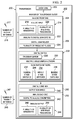
- FIG 2 a block diagram of a transponder is depicted in accordance with an illustrative embodiment.
- transponder 200 is an example of one implementation of a transponder for communications satellite 100 in Figure 1 .
- Transponder 200 may comprise a payload for communications satellite 100.
- transponder 200 may comprise a number of transponder slices 202 connected to backplane 203.
- Backplane 203 may comprise any structure to which any number of transponder slices 202 may be connected to provide a connection for the communication of digital signals between and among number of transponder slices 202.
- backplane 203 may be implemented as part of a housing configured for containing a number of transponder slices 202.
- a number of transponder slices 202 may be implemented on a number of circuit boards that may be configured to be plugged in to backplane 203 to connect together a number of transponder slices 202 via backplane 203.
- a number of transponders slices 202 may comprise analog front end 204, digital channelizer 206, digital switch 208, digital combiner 210, and analog back end 212.
- Analog front end 204 may be configured to receive analog input 214 from number of receive antennas 216.
- Number of receive antennas 216 may be referred to as uplink antennas.
- number of receive antennas 216 may include any appropriate number and type of antennas on a satellite configured to receive uplink beams 217 and to provide received uplink beams 217 as analog input 214 to analog front end 204.
- Analog front end 204 may be configured to receive analog input 214 comprising plurality of bandwidths 218 and plurality of interface frequencies 220.
- plurality of bandwidths 218 may be referred to as first plurality of bandwidths and plurality of interface frequencies 220 may be referred to as first plurality of interface frequencies.
- plurality of bandwidths 218 refers to how much of the frequency spectrum of analog input 214 that may be received at the inputs to analog front end 204.
- analog front end 204 may be selectively configured to receive a different plurality of bandwidths 218 of analog input 214 without changing the hardware configuration of analog front end 204.
- analog front end 204 may be configured to receive plurality of bandwidths 218 of 500 MHz, 250 MHz, 125 MHz or other bandwidths or combinations of bandwidths without changing the hardware configuration of analog front end 204.
- plurality of interface frequencies 220 refers to the locations in the frequency spectrum of analog input 214 that may be received at the inputs to analog front end 204.
- an input of analog front end 204 that is configured to receive a 500 MHz bandwidth of analog input 214 may be configured to receive plurality of interface frequencies 220 of 83-583 MHz, or 750-1250 MHz, or 1416-1916 MHz or other interface frequencies spanning a bandwidth of 500 MHz.
- an input of analog front end 204 that is configured to receive a 500 MHz bandwidth of analog input 214 may be configured to receive plurality of interface frequencies 220 of 83-583 MHz from a single one of number of receive antennas 216.
- an input of analog front end 204 that is configured to receive a 500 MHz bandwidth of analog input 214 may be configured to receive plurality of interface frequencies 220 of 83-333 MHz from a first one of number of receive antennas 216 and to receive plurality of interface frequencies 220 of 333-583 MHz from a second one of number of receive antennas 216.
- analog front end 204 may be configured to receive different plurality of interface frequencies 220 of analog input 214 without changing the hardware configuration of analog front end 204.
- Analog to digital converters 222 may be configured for converting analog input 214 received by analog front end 204 to digital signals for processing by digital channelizer 206.
- Analog to digital converters 222 may be provided as part of or separate from analog front end 204.
- Analog front end 204 may be referred to as an analog front end to digital channelizer 206.
- Digital channelizer 206 may be configured to process the digital signals derived from analog input 214 to divide the frequency spectrum of analog input 214 into plurality of frequency slices 224.
- any appropriate method or system may be implemented in digital channelizer 206 to generate plurality of frequency slices 224 from the digital signals derived from analog input 214.
- Plurality of frequency slices 224 may be routed by digital switch 208 from digital channelizer 206 to digital combiner 210.
- digital switch 208 may include crossbar switch 228, multiple stage switch network 230, or any other appropriate switch structure for routing plurality of frequency slices 224 from digital channelizer 206 to digital combiner 210.
- Crossbar switch 228 may be referred to as a cross-point switch, crosspoint switch, or matrix switch.
- Crossbar switch 228 may be implemented as an assembly of individual switches arranged in a matrix.
- Multiple stage switch network 230 may comprise groups of switches arranged in a plurality of stages.
- Multiple stage switch network 230 may comprise Clos switch network 232.
- multiple stage switch network 230 may comprise a three stage or other Clos switch network 232 comprising ingress stage switches 234, middle stage switches 236, and egress stage switches 238.
- ingress stage switches 234 may be configured to route plurality of frequency slices 224 from digital channelizer 206 to middle stage switches 236.
- Middle stage switches 236 may be configured to route plurality of frequency slices 224 from ingress stage switches 234 to egress stage switches 238.
- Egress stage switches 238 may be configured to route plurality of frequency slices 224 from middle stage switches 236 to digital combiner 210.
- digital switch 208 may be configured for routing plurality of frequency slices 224 from digital channelizer 206 to digital combiner 210 in a non-blocking manner.
- plurality of frequency slices 224 provided on any inputs to digital switch 208 may be routed by digital switch 208 to any inputs of digital combiner 210.
- digital switch 208 may be implemented in a manner such that any unused input on ingress stage switches 234 may be connected to any unused output on egress stage switches 238 to route a plurality of frequency slices 224 from digital channelizer 206 to digital combiner 210 with or without having to re-arrange existing connections between digital channelizer 206 and digital combiner 210 via digital switch 208.
- Digital combiner 210 may be configured to receive plurality of frequency slices 224 from digital switch 208 and to assemble the received frequency slices to form output sub-bands 240. Any appropriate method or system may be implemented in digital combiner 210 to form output sub-bands 240 from the frequency slices received from digital switch 208.
- Digital to analog converters 242 may be configured to convert output sub-bands 240 to analog output 244.
- Digital to analog converters 242 may be provided as part of or separate from analog back end 212.
- Analog back end 212 may be referred to as an analog back end for digital combiner 210.
- Analog back end 212 may be configured to transmit analog output 244 via a number of transmit antennas 246. A number of transmit antennas 246 may be referred to as downlink antennas.
- a number of transmit antennas 246 may include any appropriate number and type of antennas on a satellite configured to transmit analog output 244 from analog back end 212 as downlink beams 247.
- analog back end 212 may be configured to transmit analog output 244 at plurality of bandwidths 248 and plurality of interface frequencies 250.
- Plurality of bandwidths 248 may be referred to as second plurality of bandwidths.
- Plurality of interface frequencies 250 may be referred to as second plurality of interface frequencies.
- Plurality of bandwidths 248 of analog output 244 may be the same as or different from plurality of bandwidths 218 of analog input 214.
- Plurality of interface frequencies 250 of analog output 244 may be the same as or different from plurality of interface frequencies 220 of analog input 214.
- analog back end 212 may be selectively configured to transmit analog output 244 at a different plurality of bandwidths 248 and a different plurality of interface frequencies 250 without changing the hardware configuration of analog back end 212.
- the illustration of Figure 2 is not meant to imply physical or architectural limitations to the manner in which different illustrative embodiments may be implemented. Other components in addition to, in place of, or both in addition to and in place of the ones illustrated may be used. Some components may be unnecessary in some illustrative embodiments. Also, the blocks are presented to illustrate some functional components.
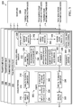
- transponder 300 is an example of one implementation of transponder 200 in Figure 2 .
- transponder 300 includes transponder slice 302, transponder slice 304, transponder slice 306, and transponder slice 308 connected to backplane 309.
- Backplane 309 may comprise any structure to which any number of transponder slices may be connected to provide a connection for the communication of digital signals between and among the transponder slices.
- backplane 309 may be implemented as part of a housing configured for containing transponder slice 302, transponder slice 304, transponder slice 306, and transponder slice 308.
- each of transponder slice 302, transponder slice 304, transponder slice 306, and transponder slice 308 may be implemented on a circuit board or other appropriate structure that may be configured to be plugged in to backplane 309 to connect together transponder slice 302, transponder slice 304, transponder slice 306, and transponder slice 308 via backplane 309.
- Transponder 300 may include more or fewer than four transponder slices connected to backplane 309.
- each of transponder slice 302, transponder slice 304, transponder slice 306, and transponder slice 308 may be implemented as a modular building block.
- transponder systems providing different processing capacity may be provided by connecting the appropriate number of transponder slices to backplane 309.
- Transponder slice 302 will be described in greater detail.
- Transponder slice 304, transponder slice 306, and transponder slice 308 may be implemented in a manner similar to transponder slice 302.
- transponder slice 302, transponder slice 304, transponder slice 306, and transponder slice 308 may have identical hardware configurations.
- Transponder slice 302 may include analog portion 310 and digital processing portion 312.
- Analog portion 310 may include analog input 316, analog to digital converter 318, digital to analog converter 320, and analog output 322.
- Analog input 316 and analog to digital converter 318 may form an analog front end for digital channelizer 324 in digital processing portion 312.
- Digital to analog converter 320 and analog output 322 may form an analog back end for digital combiner 326 in digital processing portion 312.
- Digital channelizer 324 may be configured to process the digital signals provided by analog to digital converter 318 to generate frequency slices.
- Digital combiner 326 may be configured to assemble the frequency slices to form output sub-bands.
- Digital processing portion 312 may comprise digital switch 328.
- Digital switch 328 may be configured to route the frequency slices generated by digital channelizer 324 to digital combiner 326.
- Digital switch 328 also may be configured to route frequency slices generated by digital channelizer 324 to digital combiners on transponder slice 304, transponder slice 306, and transponder slice 308. Similarly, digital switch 328 may be configured to route frequency slices generated by digital channelizers on transponder slice 304, transponder slice 306, and transponder slice 308 to digital combiner 326 on transponder slice 302.
- digital processing portion 312 may be configured to provide processing for N MHz of bandwidth.
- Analog portion 310 may include ports 332. For example, without limitation, ports 332 may include n input ports 334 for analog front end 316 and m output ports 336 for analog back end 322.
- the number of n input ports 334 may be the same as or different from the number of m output ports 336.
- analog portion 310 may be configured to allow the processing for N MHz of bandwidth 330 provided by digital processing portion 312 to be arbitrarily split across n input ports 334 and m output ports 336 such that each of n input ports 334 provides N/n MHz of bandwidth and each of m output ports 336 provides N/m MHz of bandwidth.
- each of n input ports 334 may be configured to provide the same or different bandwidth as each of m output ports 336.
- ports 332 may be configured to provide one 500 MHz input port and one 500 MHs output port, two 250 MHz input ports and two 250 MHz output ports, four 125 MHz input ports and four 125 MHz output ports, or another number of input ports and output ports where the total bandwidth of all of the input ports is 500 MHz and the total bandwidth of all of the output ports is 500 MHz.
- analog portion 310 also may be configured to allow flexible selection of plurality of interface frequencies 340 for n input ports 334 and m output ports 336.
- digital switch 328 may be a portion of a three stage switch network that includes ingress stage switches 342, middle stage switches 344, and egress stage switches 346.
- Frequency slices from digital channelizer 324 may be routed by ingress stage switches 342 to middle stage switches 344 on transponder slice 302 and to middle stage switches on transponder slice 304, transponder slice 306, and transponder slice 308.
- Frequency slices may be routed to middle stage switches 344 on transponder slice 302 from ingress stage switches 342 on transponder slice 302 and from ingress stage switches on transponder slice 304, transponder slice 306, and transponder slice 308.
- Frequency slices may be routed from middle stage switches 344 on transponder slice 302 to egress stage switches 346 on transponder slice 302 and to egress stage switches on transponder slice 304, transponder slice 306, and transponder slice 308. Frequency slices also may be routed to egress stage switches 346 on transponder slice 302 from middle stage switches on transponder slice 304, transponder slice 306, and transponder slice 308. Frequency slices may be routed from egress stage switches 346 on transponder slice 302 to digital combiner 326.
- digital processing portion 312 may be configured to perform various types of digital signal processing on the frequency slices generated by digital channelizer 324 before the frequency slices are assembled by digital combiner 326 to form output sub-bands.
- processing may include frequency hopping 348, digital level and phase control 350, or other types of digital signal processing or various types of digital signal processing in various combinations.
- Frequency hopping 348 may be implemented to provide protection against interference and jamming.
- frequency hopping 348 may comprise permuting frequency slices in a pseudo-random, time-varying fashion with a permute key known to a satellite and to the satellite terminals but not to potential sources of interference.
- digital level and phase control 350 may include adjusting the power or voltage level or phase of the communications processed through the transponder by digital signal processing of the digital frequency slices, by means of fixed gain or phase settings, automatic level control, voltage limiting, power limiting, or by other means, which can be applied at the individual digital frequency slices or across arbitrary groups of slices.
- digital level control 350 may be used to provide individual customers with appropriate power levels for their communications via a communications satellite.
- digital channelizer 324, digital combiner 326, digital switch 328, and other functionality of digital processing portion 312 may be implemented by a number of application specific integrated circuits 352, number of field programmable gate arrays 353, or by any other suitable technology on transponder slice 302.
- the control of digital channelizer 324, digital combiner 326, digital switch 328, and other functionality of digital processing portion 312 may be implemented by number of application specific integrated circuits 352 on transponder slice 302 or in any other appropriate manner.
- the illustration of Figure 3 is not meant to imply physical or architectural limitations to the manner in which different illustrative embodiments may be implemented. Other components in addition to, in place of, or both in addition to and in place of the ones illustrated may be used.
- each block in the block diagrams may represent a module, segment, or portion of code, which comprises one or more executable instructions for implementing the specified logical function or functions. It should also be noted that, in some alternative implementations, the functions noted in a block may occur out of the order noted in the figures.
Landscapes
- Engineering & Computer Science (AREA)
- Physics & Mathematics (AREA)
- Astronomy & Astrophysics (AREA)
- Aviation & Aerospace Engineering (AREA)
- General Physics & Mathematics (AREA)
- Computer Networks & Wireless Communication (AREA)
- Signal Processing (AREA)
- Radio Relay Systems (AREA)
Claims (14)
- Dispositif, comprenant :un transpondeur (200) comprenant une quantité de tranches de transpondeur (202), chacune de la quantité de tranches de transpondeur comprenant (202) :une extrémité frontale analogique (204) configurée pour recevoir une entrée analogique (214) ;des convertisseurs analogiques-numériques (222) configurés pour convertir l'entrée analogique (214) en signaux numériques ;un canaliseur numérique (206) configuré pour traiter les signaux numériques afin de générer une pluralité de tranches de fréquence (224) ; etun combineur numérique (210) configuré pour assembler la pluralité de tranches de fréquence (224) afin de former des sous-bandes de sortie (240) ;caractérisé en ce que chacune de la quantité de tranches de transpondeur (202) comprend en outre :un commutateur numérique (208) configuré pour router la pluralité de tranches de fréquence (224) depuis le canaliseur numérique (206) d'une première tranche de transpondeur jusqu'à un combineur numérique (210) d'une seconde tranche de transpondeur, le commutateur numérique (208) comprenant un réseau de commutation CLOS au moins à trois niveaux (232) comprenant des commutateurs de niveau entrant (234), des commutateurs de niveau médian (236), et des commutateurs de niveau sortant (238), et dans lequel les commutateurs de niveau entrant (234) sont configurés pour router la pluralité de tranches de fréquence (224) vers des commutateurs de niveau médian (236) sur la tranche de transpondeur et vers des commutateurs de niveau médian (236) sur une quantité d'autres tranches de transpondeur (202).
- Dispositif selon la revendication 1, dans lequel chacune de la quantité de tranches de transpondeur (202) comprend en outre :des convertisseurs numériques-analogiques (242) configurés pour convertir les sous-bandes de sortie (240) vers une sortie analogique (244) ; etune extrémité dorsale analogique (212) configurée pour transmettre la sortie analogique (244)
- Dispositif selon la revendication 2, dans lequel :l'extrémité frontale analogique (204) est configurée pour recevoir l'entrée analogique (214) comprenant une première pluralité de bandes passantes et une première pluralité de fréquences d'interface ; etl'extrémité dorsale analogique (212) est configurée pour transmettre la sortie analogique (244) comprenant une seconde pluralité de bandes passantes et une seconde pluralité de fréquences d'interface.
- Dispositif selon une quelconque des revendications 1 à 3, dans lequel :le canaliseur numérique (206), le combineur numérique (210), et le commutateur numérique (208) sont configurés pour traiter N MHz de bande passante (330) ;l'extrémité frontale analogique (204) comprend n ports d'entrée (334) configurés pour traiter une somme totale de N MHz de bande passante (330), chacun des n ports d'entrée (334) étant configuré pour recevoir un montant arbitraire de bande passante inférieur ou égal à N MHz de l'entrée analogique (214) ; etune extrémité dorsale analogique (212) configurée pour transmettre la sortie analogique (244) comprend m ports de sortie (336) configurés pour traiter une somme totale de N MHz de bande passante (330), chacun des m ports de sortie (336) étant configuré pour transmettre un montant arbitraire de bande passante inférieur ou égal à N MHz de la sortie analogique (244).
- Dispositif selon une quelconque des revendications 1 à 4, dans lequel le dispositif comprend une charge utile sur un satellite de communications (100).
- Dispositif selon une quelconque des revendications 1 à 5, dans lequel les commutateurs de niveau médian (236) sont configurés pour router la pluralité de tranches de fréquence (224) depuis les commutateurs de niveau entrant (234) sur la tranche de transpondeur et depuis des commutateurs de niveau entrant (234) sur la quantité d'autres tranches de transpondeur (202) jusqu'aux commutateurs de niveau sortant (238) sur la tranche de transpondeur et jusqu'à des commutateurs de niveau sortant (238) sur la quantité d'autres tranches de transpondeur (202).
- Dispositif selon une quelconque des revendications 1 à 6, dans lequel les commutateurs de niveau sortant (238) sont configurés pour router la pluralité de tranches de fréquence (202) depuis les commutateurs de niveau médian (236) sur la tranche de transpondeur et depuis les commutateurs de niveau médian (234) sur la quantité d'autres tranches de transpondeur (202) jusqu'au combineur numérique (210).
- Dispositif selon une quelconque des revendications 1 à 7, dans lequel la partie de traitement numérique est mise en oeuvre dans une technologie appropriée choisie à partir d'une quantité de circuits intégrés spécifiques à l'application et une quantité de réseaux prédiffusés programmables de champ.
- Dispositif selon une quelconque des revendications 1 à 8, dans lequel la partie de traitement numérique est configurée pour fournir des sauts de fréquence.
- Dispositif selon une quelconque des revendications 1 à 9, dans lequel la partie de traitement numérique est configurée pour fournir une commande de phase et de niveau numérique.
- Dispositif selon une quelconque des revendications 1 à 10, dans lequel une tranche de transpondeur est configurée pour être connectée à un fond de panier conjointement avec une quantité d'autres tranches de transpondeur (202).
- Procédé de traitement de données de communications par satellite, consistant à :recevoir un faisceau de liaison montante (112) provenant d'une station terrestre (102) par une extrémité frontale analogique (204) d'une charge utile sur le satellite (100) ;convertir le faisceau de liaison montante (112) en signaux numériques par la charge utile ;traiter les signaux numériques par un canaliseur numérique (206) d'une première tranche de transpondeur afin de générer une pluralité de tranches de fréquence (224) ;router la pluralité de tranches de fréquence (224) depuis le canaliseur numérique (206) jusqu'à un combineur numérique (210) d'une seconde tranche de transpondeur par un commutateur numérique (208) de la première tranche de transpondeur, le commutateur numérique comprenant un réseau de commutation CLOS au moins à trois niveaux (232) comprenant des commutateurs de niveau entrant (234), des commutateurs de niveau médian (236), et des commutateurs de niveau sortant (238), et les commutateurs de niveau entrant étant configurés pour router la pluralité de tranches de fréquence vers des commutateurs de niveau médian sur la tranche de transpondeur et vers des commutateurs de niveau médian sur une quantité d'autres tranches de transpondeur ; etassembler la pluralité de tranches de fréquence (224) par un combineur numérique (210) pour former des sous-bandes de sortie (240).
- Procédé selon la revendication 12 consistant en outre à :convertir les sous-bandes de sortie (240) en un faisceau de liaison descendante (114) par la charge utile ; ettransmettre le faisceau de liaison descendante (114) par une extrémité dorsale analogique (212) de la charge utile.
- Procédé selon la revendication 13, dans lequel :la réception du faisceau de liaison montante consiste à recevoir une entrée analogique (214) comprenant une première pluralité de bandes passantes (218) et une première pluralité de fréquences d'interface (220) ; etla transmission du faisceau de liaison descendante (114) consiste à transmettre une sortie analogique comprenant une seconde pluralité de bandes passantes (248) et une seconde pluralité de fréquences d'interface (250).
Priority Applications (2)
| Application Number | Priority Date | Filing Date | Title |
|---|---|---|---|
| EP16176223.2A EP3091673B1 (fr) | 2012-11-01 | 2013-10-31 | Transpondeur de satellite avec un système et une méthode de traitement de données de communication par conversion analogique digitale, formation de canaux fréquentiels et leur combinaison par un commutateur à plusieurs étages |
| EP17200881.5A EP3297181A1 (fr) | 2012-11-01 | 2013-10-31 | Transpondeur de satellite avec un système et une méthode de traitement de données de communication par conversion analogique digitale, formation de canaux fréquentiels et leur combinaison par un commutateur à plusieurs étages. |
Applications Claiming Priority (1)
| Application Number | Priority Date | Filing Date | Title |
|---|---|---|---|
| US13/666,449 US9954602B2 (en) | 2012-11-01 | 2012-11-01 | Satellite communications data processing |
Related Child Applications (3)
| Application Number | Title | Priority Date | Filing Date |
|---|---|---|---|
| EP16176223.2A Division EP3091673B1 (fr) | 2012-11-01 | 2013-10-31 | Transpondeur de satellite avec un système et une méthode de traitement de données de communication par conversion analogique digitale, formation de canaux fréquentiels et leur combinaison par un commutateur à plusieurs étages |
| EP16176223.2A Division-Into EP3091673B1 (fr) | 2012-11-01 | 2013-10-31 | Transpondeur de satellite avec un système et une méthode de traitement de données de communication par conversion analogique digitale, formation de canaux fréquentiels et leur combinaison par un commutateur à plusieurs étages |
| EP17200881.5A Division EP3297181A1 (fr) | 2012-11-01 | 2013-10-31 | Transpondeur de satellite avec un système et une méthode de traitement de données de communication par conversion analogique digitale, formation de canaux fréquentiels et leur combinaison par un commutateur à plusieurs étages. |
Publications (3)
| Publication Number | Publication Date |
|---|---|
| EP2728770A2 EP2728770A2 (fr) | 2014-05-07 |
| EP2728770A3 EP2728770A3 (fr) | 2014-07-30 |
| EP2728770B1 true EP2728770B1 (fr) | 2016-08-03 |
Family
ID=49517331
Family Applications (3)
| Application Number | Title | Priority Date | Filing Date |
|---|---|---|---|
| EP17200881.5A Withdrawn EP3297181A1 (fr) | 2012-11-01 | 2013-10-31 | Transpondeur de satellite avec un système et une méthode de traitement de données de communication par conversion analogique digitale, formation de canaux fréquentiels et leur combinaison par un commutateur à plusieurs étages. |
| EP13191118.2A Revoked EP2728770B1 (fr) | 2012-11-01 | 2013-10-31 | Transpondeur de satellite avec un système et une méthode de traitement de données de communication par conversion analogique digitale, formation de canaux fréquentiels et leur combinaison par un commutateur à plusieurs étages. |
| EP16176223.2A Revoked EP3091673B1 (fr) | 2012-11-01 | 2013-10-31 | Transpondeur de satellite avec un système et une méthode de traitement de données de communication par conversion analogique digitale, formation de canaux fréquentiels et leur combinaison par un commutateur à plusieurs étages |
Family Applications Before (1)
| Application Number | Title | Priority Date | Filing Date |
|---|---|---|---|
| EP17200881.5A Withdrawn EP3297181A1 (fr) | 2012-11-01 | 2013-10-31 | Transpondeur de satellite avec un système et une méthode de traitement de données de communication par conversion analogique digitale, formation de canaux fréquentiels et leur combinaison par un commutateur à plusieurs étages. |
Family Applications After (1)
| Application Number | Title | Priority Date | Filing Date |
|---|---|---|---|
| EP16176223.2A Revoked EP3091673B1 (fr) | 2012-11-01 | 2013-10-31 | Transpondeur de satellite avec un système et une méthode de traitement de données de communication par conversion analogique digitale, formation de canaux fréquentiels et leur combinaison par un commutateur à plusieurs étages |
Country Status (3)
| Country | Link |
|---|---|
| US (1) | US9954602B2 (fr) |
| EP (3) | EP3297181A1 (fr) |
| JP (1) | JP6359261B2 (fr) |
Families Citing this family (30)
| Publication number | Priority date | Publication date | Assignee | Title |
|---|---|---|---|---|
| US9588213B2 (en) | 2014-02-18 | 2017-03-07 | Raytheon Company | Analog signal processing method for accurate single antenna direction finding |
| US9590760B2 (en) | 2014-06-03 | 2017-03-07 | Raytheon Company | Analog RF memory system |
| US9645972B2 (en) | 2014-06-16 | 2017-05-09 | Raytheon Company | Butterfly channelizer |
| US9485125B2 (en) | 2014-06-16 | 2016-11-01 | Raytheon Company | Dynamically reconfigurable channelizer |
| GB201415684D0 (en) * | 2014-09-04 | 2014-10-22 | Airbus Defence & Space Ltd | Scalable Architecture For Digital Signal Process |
| US10027026B2 (en) | 2014-09-18 | 2018-07-17 | Raytheon Company | Programmable beamforming system including element-level analog channelizer |
| CA3010294C (fr) * | 2016-03-02 | 2019-01-08 | Mitsubishi Electric Corporation | Systeme de communication satellite multifaisceau |
| CA2996469A1 (fr) * | 2016-04-07 | 2017-10-12 | Thales Alenia Space Italia S.P.A. Con Unico Socio | Processeur hybride a commande de commutation basee sur une attribution dynamique de largeur de bande pour systeme de satellite multifaisceau |
| EP3253049B1 (fr) * | 2016-06-03 | 2020-09-30 | Unitron NV | Système de distribution de signaux de fréquence radio numérique |
| US10320481B2 (en) | 2016-07-13 | 2019-06-11 | Space Systems/Loral, Llc | Flexible high throughput satellite system using optical gateways |
| US10069565B2 (en) | 2016-08-03 | 2018-09-04 | Space Systems/Loral, Llc | Satellite system using optical gateways and onboard processing |
| US10348338B2 (en) | 2016-10-06 | 2019-07-09 | Raytheon Company | Adaptive channelizer |
| US10165438B2 (en) | 2017-03-06 | 2018-12-25 | The Boeing Company | Secured multi-payload antennas operators operations |
| US11394458B2 (en) | 2017-03-06 | 2022-07-19 | The Boeing Company | Inband telemetry for a virtual transponder |
| US11101879B2 (en) | 2017-03-06 | 2021-08-24 | The Boeing Company | Virtual transponder |
| US10673825B2 (en) * | 2017-03-06 | 2020-06-02 | The Boeing Company | Protected multi-operators payload operations |
| US10516992B2 (en) | 2017-03-06 | 2019-12-24 | The Boeing Company | Commercial satellite operations with secure enclave for payload operations |
| US10419403B2 (en) | 2017-03-06 | 2019-09-17 | The Boeing Company | Virtual transponder utilizing inband commanding |
| US10530751B2 (en) | 2017-03-06 | 2020-01-07 | The Boeing Company | Virtual transponder utilizing inband telemetry |
| US10728221B2 (en) * | 2017-03-06 | 2020-07-28 | The Boeing Company | Hosted payload operations |
| US11201707B2 (en) | 2017-03-06 | 2021-12-14 | The Boeing Company | Secured independent hosted payload operations |
| CA3057374C (fr) * | 2017-04-04 | 2023-04-11 | SEAKR Engineering, Inc. | Architecture repliee souple de traitement de formation de faisceau, de decoupage en canaux et de routage pour charges utiles satellitaires numeriques |
| US10177460B2 (en) | 2017-04-24 | 2019-01-08 | Blue Digs LLC | Satellite array architecture |
| US10084587B1 (en) | 2017-07-28 | 2018-09-25 | Raytheon Company | Multifunction channelizer/DDC architecture for a digital receiver/exciter |
| KR101887013B1 (ko) * | 2018-06-07 | 2018-08-09 | 한화시스템 주식회사 | 이동형 위성 통신 시스템에서 블로킹 보상 방법 |
| KR101895845B1 (ko) * | 2018-06-29 | 2018-09-07 | 한화시스템 주식회사 | 이동형 위성 통신 시스템에서 블로킹 보상 방법 |
| US11070285B2 (en) | 2019-02-15 | 2021-07-20 | The Boeing Company | System and method for configuring a multistage interconnection network based on user traffic demand |
| EP4309289A4 (fr) | 2021-03-17 | 2025-02-12 | Fairwinds Technologies, LLC | Appareil et procédés de traitement de signal |
| US20240243762A1 (en) * | 2022-08-04 | 2024-07-18 | Anuvu Ip Holdings Llc | Network management system for software defined radio networks for use in mobile networks |
| US20240048458A1 (en) * | 2022-08-04 | 2024-02-08 | Anuvu Ip Holdings Llc | Network management system for software defined radio networks for use in mobile networks |
Citations (6)
| Publication number | Priority date | Publication date | Assignee | Title |
|---|---|---|---|---|
| US4931802A (en) | 1988-03-11 | 1990-06-05 | Communications Satellite Corporation | Multiple spot-beam systems for satellite communications |
| EP1139584A2 (fr) | 2000-03-29 | 2001-10-04 | The Boeing Company | Matrice de commutation pour équipement de satellite ayant de multiples pinceaux d'antenne montants et un traitement de signal à bord |
| WO2004073229A2 (fr) | 2003-01-28 | 2004-08-26 | The Boeing Company | Systemes et procedes de traitement numerique de donnees de communications satellite |
| US20050275504A1 (en) | 2004-06-10 | 2005-12-15 | Anthony Torza | Reconfigurable switch having an overlapping Clos Architecture |
| WO2009144096A1 (fr) | 2008-04-18 | 2009-12-03 | Astrium Limited | Système de traitement numérique modulaire pour données utiles de satellite de télécommunications |
| EP2184866A1 (fr) | 2008-11-06 | 2010-05-12 | Com Dev International Limited | Transpondeur transparent numérique flexible |
Family Cites Families (7)
| Publication number | Priority date | Publication date | Assignee | Title |
|---|---|---|---|---|
| JPH05227246A (ja) | 1992-02-17 | 1993-09-03 | Fujitsu Ltd | 動的結合用チャネルスイッチャー |
| US6584140B1 (en) * | 1999-01-22 | 2003-06-24 | Systems Information And Electronic Systems Integration Inc. | Spectrum efficient fast frequency-hopped modem with coherent demodulation |
| DE10210037A1 (de) * | 2002-03-07 | 2003-10-02 | Siemens Ag | Aktiver Backscatter-Transponder, Kommunikationssystem mit einem solchen und Verfahren zum Übertragen von Daten mit einem solchen aktiven Backscatter-Transponder |
| JP2007266858A (ja) | 2006-03-28 | 2007-10-11 | Akita Univ | スイッチ制御回路 |
| JP5213876B2 (ja) | 2006-12-20 | 2013-06-19 | アストリウム・リミテッド | ビーム形成システム及び方法 |
| JP2011199355A (ja) * | 2010-03-17 | 2011-10-06 | Mitsubishi Electric Corp | 衛星搭載用中継器 |
| JP5984468B2 (ja) * | 2012-04-10 | 2016-09-06 | 三菱電機株式会社 | 中継器及び中継システム |
-
2012
- 2012-11-01 US US13/666,449 patent/US9954602B2/en active Active
-
2013
- 2013-10-31 EP EP17200881.5A patent/EP3297181A1/fr not_active Withdrawn
- 2013-10-31 EP EP13191118.2A patent/EP2728770B1/fr not_active Revoked
- 2013-10-31 EP EP16176223.2A patent/EP3091673B1/fr not_active Revoked
- 2013-10-31 JP JP2013226370A patent/JP6359261B2/ja active Active
Patent Citations (6)
| Publication number | Priority date | Publication date | Assignee | Title |
|---|---|---|---|---|
| US4931802A (en) | 1988-03-11 | 1990-06-05 | Communications Satellite Corporation | Multiple spot-beam systems for satellite communications |
| EP1139584A2 (fr) | 2000-03-29 | 2001-10-04 | The Boeing Company | Matrice de commutation pour équipement de satellite ayant de multiples pinceaux d'antenne montants et un traitement de signal à bord |
| WO2004073229A2 (fr) | 2003-01-28 | 2004-08-26 | The Boeing Company | Systemes et procedes de traitement numerique de donnees de communications satellite |
| US20050275504A1 (en) | 2004-06-10 | 2005-12-15 | Anthony Torza | Reconfigurable switch having an overlapping Clos Architecture |
| WO2009144096A1 (fr) | 2008-04-18 | 2009-12-03 | Astrium Limited | Système de traitement numérique modulaire pour données utiles de satellite de télécommunications |
| EP2184866A1 (fr) | 2008-11-06 | 2010-05-12 | Com Dev International Limited | Transpondeur transparent numérique flexible |
Non-Patent Citations (3)
| Title |
|---|
| CÉLINE HAARDT ET AL., INTERNET SWITCHING BY SATELLITE: AN ULTRA-FAST PROCESSOR WITH RADIO BURST SWITCHING, 24 May 2005 (2005-05-24), pages 1 - 18, XP055378728 |
| CHARLES CLOS: "A study of Non-blocking Switching Networks", THE BELL SYSTEM TECHNICAL JOURNAL, 30 October 1953 (1953-10-30), pages 406 - 424, XP011630698 |
| SCHWARTZ MISCHA: "Telecommunication Networks: Protocols, Modeling and Analysis", WESLEY PUBLISHING COMPANY, article MISHA SCHWARTZ, XP055378724 |
Also Published As
| Publication number | Publication date |
|---|---|
| EP3091673A2 (fr) | 2016-11-09 |
| EP2728770A2 (fr) | 2014-05-07 |
| US9954602B2 (en) | 2018-04-24 |
| EP3091673A3 (fr) | 2016-11-16 |
| EP3297181A1 (fr) | 2018-03-21 |
| JP2014096795A (ja) | 2014-05-22 |
| EP3091673B1 (fr) | 2018-02-14 |
| US20140119385A1 (en) | 2014-05-01 |
| EP2728770A3 (fr) | 2014-07-30 |
| JP6359261B2 (ja) | 2018-07-18 |
Similar Documents
| Publication | Publication Date | Title |
|---|---|---|
| EP2728770B1 (fr) | Transpondeur de satellite avec un système et une méthode de traitement de données de communication par conversion analogique digitale, formation de canaux fréquentiels et leur combinaison par un commutateur à plusieurs étages. | |
| US10135523B2 (en) | Hitless rearrangement of a satellite-hosted switch via propagated synchronization | |
| EP2737642B1 (fr) | Déploiement incremental de stations d'interface dans un système de communication par satellite étoilé utilisant des faisceaux d'antenne statiques | |
| EP0854590B1 (fr) | Processeur analogique pour satellites numériques | |
| ES2554286T3 (es) | Método y aparato para encaminar paquetes de IP en redes de satélites multi-haz | |
| US10700755B2 (en) | Antenna mapping and diversity | |
| EP1590906A2 (fr) | Systemes et procedes de traitement numerique de donnees de communications satellite | |
| RU2709283C2 (ru) | Новая архитектура fdma/tdma с использованием канального приёмника и матричного усилителя мощности | |
| CA2157209C (fr) | Repeteurs pour satellites multifaisceau | |
| US11463160B2 (en) | Flexible intra-satellite signal pathways | |
| JP2003249884A (ja) | 柔軟性ハブ−スポーク衛星通信ネットワークを実装するための装置および方法 | |
| US20100226307A1 (en) | Routing of downlink channels in a communications satellite | |
| EP3954059B1 (fr) | Émission et réception à entrées multiples et sorties multiples | |
| CA2887759C (fr) | Systeme de telecommunication par satellite et methode incluant la couverture multipoint et la distribution a capacite variable | |
| JP2003234684A (ja) | 中間周波数応答ペイロード実装 | |
| WO2022260949A1 (fr) | Systèmes et procédés pour générer des données d'étalonnage dans des modules d'antenne active ayant des réseaux de filtres côté antenne | |
| US20030134594A1 (en) | Downlink switching mechanism for a satellite | |
| CN221710081U (zh) | 一种多通道低轨卫星星载移动通信基站载荷 | |
| EP0760561B1 (fr) | Répéteurs pour satellites à pinceaux multiples avec des canaux divisés en sous canaux et commutation d'un pinceau sur l'autre |
Legal Events
| Date | Code | Title | Description |
|---|---|---|---|
| PUAI | Public reference made under article 153(3) epc to a published international application that has entered the european phase |
Free format text: ORIGINAL CODE: 0009012 |
|
| 17P | Request for examination filed |
Effective date: 20131031 |
|
| AK | Designated contracting states |
Kind code of ref document: A2 Designated state(s): AL AT BE BG CH CY CZ DE DK EE ES FI FR GB GR HR HU IE IS IT LI LT LU LV MC MK MT NL NO PL PT RO RS SE SI SK SM TR |
|
| AX | Request for extension of the european patent |
Extension state: BA ME |
|
| PUAL | Search report despatched |
Free format text: ORIGINAL CODE: 0009013 |
|
| AK | Designated contracting states |
Kind code of ref document: A3 Designated state(s): AL AT BE BG CH CY CZ DE DK EE ES FI FR GB GR HR HU IE IS IT LI LT LU LV MC MK MT NL NO PL PT RO RS SE SI SK SM TR |
|
| AX | Request for extension of the european patent |
Extension state: BA ME |
|
| RIC1 | Information provided on ipc code assigned before grant |
Ipc: H04B 7/185 20060101AFI20140624BHEP |
|
| TPAC | Observations filed by third parties |
Free format text: ORIGINAL CODE: EPIDOSNTIPA |
|
| 17Q | First examination report despatched |
Effective date: 20150323 |
|
| GRAP | Despatch of communication of intention to grant a patent |
Free format text: ORIGINAL CODE: EPIDOSNIGR1 |
|
| INTG | Intention to grant announced |
Effective date: 20160211 |
|
| GRAS | Grant fee paid |
Free format text: ORIGINAL CODE: EPIDOSNIGR3 |
|
| GRAA | (expected) grant |
Free format text: ORIGINAL CODE: 0009210 |
|
| AK | Designated contracting states |
Kind code of ref document: B1 Designated state(s): AL AT BE BG CH CY CZ DE DK EE ES FI FR GB GR HR HU IE IS IT LI LT LU LV MC MK MT NL NO PL PT RO RS SE SI SK SM TR |
|
| REG | Reference to a national code |
Ref country code: GB Ref legal event code: FG4D |
|
| REG | Reference to a national code |
Ref country code: CH Ref legal event code: EP Ref country code: AT Ref legal event code: REF Ref document number: 817928 Country of ref document: AT Kind code of ref document: T Effective date: 20160815 |
|
| REG | Reference to a national code |
Ref country code: IE Ref legal event code: FG4D |
|
| REG | Reference to a national code |
Ref country code: DE Ref legal event code: R096 Ref document number: 602013010021 Country of ref document: DE |
|
| REG | Reference to a national code |
Ref country code: FR Ref legal event code: PLFP Year of fee payment: 4 |
|
| REG | Reference to a national code |
Ref country code: NL Ref legal event code: MP Effective date: 20160803 |
|
| REG | Reference to a national code |
Ref country code: LT Ref legal event code: MG4D |
|
| REG | Reference to a national code |
Ref country code: AT Ref legal event code: MK05 Ref document number: 817928 Country of ref document: AT Kind code of ref document: T Effective date: 20160803 |
|
| PG25 | Lapsed in a contracting state [announced via postgrant information from national office to epo] |
Ref country code: NO Free format text: LAPSE BECAUSE OF FAILURE TO SUBMIT A TRANSLATION OF THE DESCRIPTION OR TO PAY THE FEE WITHIN THE PRESCRIBED TIME-LIMIT Effective date: 20161103 Ref country code: FI Free format text: LAPSE BECAUSE OF FAILURE TO SUBMIT A TRANSLATION OF THE DESCRIPTION OR TO PAY THE FEE WITHIN THE PRESCRIBED TIME-LIMIT Effective date: 20160803 Ref country code: IS Free format text: LAPSE BECAUSE OF FAILURE TO SUBMIT A TRANSLATION OF THE DESCRIPTION OR TO PAY THE FEE WITHIN THE PRESCRIBED TIME-LIMIT Effective date: 20161203 Ref country code: HR Free format text: LAPSE BECAUSE OF FAILURE TO SUBMIT A TRANSLATION OF THE DESCRIPTION OR TO PAY THE FEE WITHIN THE PRESCRIBED TIME-LIMIT Effective date: 20160803 Ref country code: NL Free format text: LAPSE BECAUSE OF FAILURE TO SUBMIT A TRANSLATION OF THE DESCRIPTION OR TO PAY THE FEE WITHIN THE PRESCRIBED TIME-LIMIT Effective date: 20160803 Ref country code: LT Free format text: LAPSE BECAUSE OF FAILURE TO SUBMIT A TRANSLATION OF THE DESCRIPTION OR TO PAY THE FEE WITHIN THE PRESCRIBED TIME-LIMIT Effective date: 20160803 Ref country code: RS Free format text: LAPSE BECAUSE OF FAILURE TO SUBMIT A TRANSLATION OF THE DESCRIPTION OR TO PAY THE FEE WITHIN THE PRESCRIBED TIME-LIMIT Effective date: 20160803 |
|
| PG25 | Lapsed in a contracting state [announced via postgrant information from national office to epo] |
Ref country code: SE Free format text: LAPSE BECAUSE OF FAILURE TO SUBMIT A TRANSLATION OF THE DESCRIPTION OR TO PAY THE FEE WITHIN THE PRESCRIBED TIME-LIMIT Effective date: 20160803 Ref country code: BE Free format text: LAPSE BECAUSE OF NON-PAYMENT OF DUE FEES Effective date: 20161031 Ref country code: GR Free format text: LAPSE BECAUSE OF FAILURE TO SUBMIT A TRANSLATION OF THE DESCRIPTION OR TO PAY THE FEE WITHIN THE PRESCRIBED TIME-LIMIT Effective date: 20161104 Ref country code: LV Free format text: LAPSE BECAUSE OF FAILURE TO SUBMIT A TRANSLATION OF THE DESCRIPTION OR TO PAY THE FEE WITHIN THE PRESCRIBED TIME-LIMIT Effective date: 20160803 Ref country code: PL Free format text: LAPSE BECAUSE OF FAILURE TO SUBMIT A TRANSLATION OF THE DESCRIPTION OR TO PAY THE FEE WITHIN THE PRESCRIBED TIME-LIMIT Effective date: 20160803 Ref country code: PT Free format text: LAPSE BECAUSE OF FAILURE TO SUBMIT A TRANSLATION OF THE DESCRIPTION OR TO PAY THE FEE WITHIN THE PRESCRIBED TIME-LIMIT Effective date: 20161205 Ref country code: AT Free format text: LAPSE BECAUSE OF FAILURE TO SUBMIT A TRANSLATION OF THE DESCRIPTION OR TO PAY THE FEE WITHIN THE PRESCRIBED TIME-LIMIT Effective date: 20160803 Ref country code: ES Free format text: LAPSE BECAUSE OF FAILURE TO SUBMIT A TRANSLATION OF THE DESCRIPTION OR TO PAY THE FEE WITHIN THE PRESCRIBED TIME-LIMIT Effective date: 20160803 |
|
| PG25 | Lapsed in a contracting state [announced via postgrant information from national office to epo] |
Ref country code: EE Free format text: LAPSE BECAUSE OF FAILURE TO SUBMIT A TRANSLATION OF THE DESCRIPTION OR TO PAY THE FEE WITHIN THE PRESCRIBED TIME-LIMIT Effective date: 20160803 Ref country code: RO Free format text: LAPSE BECAUSE OF FAILURE TO SUBMIT A TRANSLATION OF THE DESCRIPTION OR TO PAY THE FEE WITHIN THE PRESCRIBED TIME-LIMIT Effective date: 20160803 |
|
| REG | Reference to a national code |
Ref country code: DE Ref legal event code: R026 Ref document number: 602013010021 Country of ref document: DE |
|
| PLBI | Opposition filed |
Free format text: ORIGINAL CODE: 0009260 |
|
| PG25 | Lapsed in a contracting state [announced via postgrant information from national office to epo] |
Ref country code: CZ Free format text: LAPSE BECAUSE OF FAILURE TO SUBMIT A TRANSLATION OF THE DESCRIPTION OR TO PAY THE FEE WITHIN THE PRESCRIBED TIME-LIMIT Effective date: 20160803 Ref country code: SK Free format text: LAPSE BECAUSE OF FAILURE TO SUBMIT A TRANSLATION OF THE DESCRIPTION OR TO PAY THE FEE WITHIN THE PRESCRIBED TIME-LIMIT Effective date: 20160803 Ref country code: BG Free format text: LAPSE BECAUSE OF FAILURE TO SUBMIT A TRANSLATION OF THE DESCRIPTION OR TO PAY THE FEE WITHIN THE PRESCRIBED TIME-LIMIT Effective date: 20161103 Ref country code: SM Free format text: LAPSE BECAUSE OF FAILURE TO SUBMIT A TRANSLATION OF THE DESCRIPTION OR TO PAY THE FEE WITHIN THE PRESCRIBED TIME-LIMIT Effective date: 20160803 Ref country code: DK Free format text: LAPSE BECAUSE OF FAILURE TO SUBMIT A TRANSLATION OF THE DESCRIPTION OR TO PAY THE FEE WITHIN THE PRESCRIBED TIME-LIMIT Effective date: 20160803 Ref country code: BE Free format text: LAPSE BECAUSE OF FAILURE TO SUBMIT A TRANSLATION OF THE DESCRIPTION OR TO PAY THE FEE WITHIN THE PRESCRIBED TIME-LIMIT Effective date: 20160803 |
|
| REG | Reference to a national code |
Ref country code: CH Ref legal event code: PL |
|
| 26 | Opposition filed |
Opponent name: AIRBUS DEFENCE AND SPACE LIMITED Effective date: 20170503 |
|
| PLAX | Notice of opposition and request to file observation + time limit sent |
Free format text: ORIGINAL CODE: EPIDOSNOBS2 |
|
| REG | Reference to a national code |
Ref country code: IE Ref legal event code: MM4A |
|
| PG25 | Lapsed in a contracting state [announced via postgrant information from national office to epo] |
Ref country code: CH Free format text: LAPSE BECAUSE OF NON-PAYMENT OF DUE FEES Effective date: 20161031 Ref country code: LI Free format text: LAPSE BECAUSE OF NON-PAYMENT OF DUE FEES Effective date: 20161031 |
|
| PG25 | Lapsed in a contracting state [announced via postgrant information from national office to epo] |
Ref country code: SI Free format text: LAPSE BECAUSE OF FAILURE TO SUBMIT A TRANSLATION OF THE DESCRIPTION OR TO PAY THE FEE WITHIN THE PRESCRIBED TIME-LIMIT Effective date: 20160803 Ref country code: LU Free format text: LAPSE BECAUSE OF NON-PAYMENT OF DUE FEES Effective date: 20161031 |
|
| PLBB | Reply of patent proprietor to notice(s) of opposition received |
Free format text: ORIGINAL CODE: EPIDOSNOBS3 |
|
| REG | Reference to a national code |
Ref country code: FR Ref legal event code: PLFP Year of fee payment: 5 |
|
| PG25 | Lapsed in a contracting state [announced via postgrant information from national office to epo] |
Ref country code: IE Free format text: LAPSE BECAUSE OF NON-PAYMENT OF DUE FEES Effective date: 20161031 |
|
| PG25 | Lapsed in a contracting state [announced via postgrant information from national office to epo] |
Ref country code: HU Free format text: LAPSE BECAUSE OF FAILURE TO SUBMIT A TRANSLATION OF THE DESCRIPTION OR TO PAY THE FEE WITHIN THE PRESCRIBED TIME-LIMIT; INVALID AB INITIO Effective date: 20131031 Ref country code: CY Free format text: LAPSE BECAUSE OF FAILURE TO SUBMIT A TRANSLATION OF THE DESCRIPTION OR TO PAY THE FEE WITHIN THE PRESCRIBED TIME-LIMIT Effective date: 20160803 |
|
| PG25 | Lapsed in a contracting state [announced via postgrant information from national office to epo] |
Ref country code: MT Free format text: LAPSE BECAUSE OF NON-PAYMENT OF DUE FEES Effective date: 20161031 Ref country code: MC Free format text: LAPSE BECAUSE OF FAILURE TO SUBMIT A TRANSLATION OF THE DESCRIPTION OR TO PAY THE FEE WITHIN THE PRESCRIBED TIME-LIMIT Effective date: 20160803 Ref country code: MK Free format text: LAPSE BECAUSE OF FAILURE TO SUBMIT A TRANSLATION OF THE DESCRIPTION OR TO PAY THE FEE WITHIN THE PRESCRIBED TIME-LIMIT Effective date: 20160803 |
|
| REG | Reference to a national code |
Ref country code: FR Ref legal event code: PLFP Year of fee payment: 6 |
|
| PG25 | Lapsed in a contracting state [announced via postgrant information from national office to epo] |
Ref country code: AL Free format text: LAPSE BECAUSE OF FAILURE TO SUBMIT A TRANSLATION OF THE DESCRIPTION OR TO PAY THE FEE WITHIN THE PRESCRIBED TIME-LIMIT Effective date: 20160803 Ref country code: TR Free format text: LAPSE BECAUSE OF FAILURE TO SUBMIT A TRANSLATION OF THE DESCRIPTION OR TO PAY THE FEE WITHIN THE PRESCRIBED TIME-LIMIT Effective date: 20160803 |
|
| RDAF | Communication despatched that patent is revoked |
Free format text: ORIGINAL CODE: EPIDOSNREV1 |
|
| STAA | Information on the status of an ep patent application or granted ep patent |
Free format text: STATUS: THE PATENT HAS BEEN GRANTED |
|
| APBM | Appeal reference recorded |
Free format text: ORIGINAL CODE: EPIDOSNREFNO |
|
| APBP | Date of receipt of notice of appeal recorded |
Free format text: ORIGINAL CODE: EPIDOSNNOA2O |
|
| APAH | Appeal reference modified |
Free format text: ORIGINAL CODE: EPIDOSCREFNO |
|
| APBQ | Date of receipt of statement of grounds of appeal recorded |
Free format text: ORIGINAL CODE: EPIDOSNNOA3O |
|
| PGFP | Annual fee paid to national office [announced via postgrant information from national office to epo] |
Ref country code: FR Payment date: 20201026 Year of fee payment: 8 Ref country code: IT Payment date: 20201023 Year of fee payment: 8 Ref country code: GB Payment date: 20201027 Year of fee payment: 8 Ref country code: DE Payment date: 20201028 Year of fee payment: 8 |
|
| REG | Reference to a national code |
Ref country code: DE Ref legal event code: R082 Ref document number: 602013010021 Country of ref document: DE Representative=s name: KILBURN & STRODE LLP, NL |
|
| REG | Reference to a national code |
Ref country code: DE Ref legal event code: R064 Ref document number: 602013010021 Country of ref document: DE Ref country code: DE Ref legal event code: R103 Ref document number: 602013010021 Country of ref document: DE |
|
| APBU | Appeal procedure closed |
Free format text: ORIGINAL CODE: EPIDOSNNOA9O |
|
| RDAG | Patent revoked |
Free format text: ORIGINAL CODE: 0009271 |
|
| STAA | Information on the status of an ep patent application or granted ep patent |
Free format text: STATUS: PATENT REVOKED |
|
| REG | Reference to a national code |
Ref country code: FI Ref legal event code: MGE |
|
| 27W | Patent revoked |
Effective date: 20210804 |
|
| GBPR | Gb: patent revoked under art. 102 of the ep convention designating the uk as contracting state |
Effective date: 20210804 |