EP0854661A2 - Four à micro-ondes avec dispositif de sécurité - Google Patents
Four à micro-ondes avec dispositif de sécurité Download PDFInfo
- Publication number
- EP0854661A2 EP0854661A2 EP97309544A EP97309544A EP0854661A2 EP 0854661 A2 EP0854661 A2 EP 0854661A2 EP 97309544 A EP97309544 A EP 97309544A EP 97309544 A EP97309544 A EP 97309544A EP 0854661 A2 EP0854661 A2 EP 0854661A2
- Authority
- EP
- European Patent Office
- Prior art keywords
- heater
- temperature
- door
- microwave oven
- cooking chamber
- Prior art date
- Legal status (The legal status is an assumption and is not a legal conclusion. Google has not performed a legal analysis and makes no representation as to the accuracy of the status listed.)
- Withdrawn
Links
Images


Classifications
-
- H—ELECTRICITY
- H05—ELECTRIC TECHNIQUES NOT OTHERWISE PROVIDED FOR
- H05B—ELECTRIC HEATING; ELECTRIC LIGHT SOURCES NOT OTHERWISE PROVIDED FOR; CIRCUIT ARRANGEMENTS FOR ELECTRIC LIGHT SOURCES, IN GENERAL
- H05B6/00—Heating by electric, magnetic or electromagnetic fields
- H05B6/64—Heating using microwaves
- H05B6/6447—Method of operation or details of the microwave heating apparatus related to the use of detectors or sensors
- H05B6/645—Method of operation or details of the microwave heating apparatus related to the use of detectors or sensors using temperature sensors
-
- H—ELECTRICITY
- H05—ELECTRIC TECHNIQUES NOT OTHERWISE PROVIDED FOR
- H05B—ELECTRIC HEATING; ELECTRIC LIGHT SOURCES NOT OTHERWISE PROVIDED FOR; CIRCUIT ARRANGEMENTS FOR ELECTRIC LIGHT SOURCES, IN GENERAL
- H05B6/00—Heating by electric, magnetic or electromagnetic fields
- H05B6/64—Heating using microwaves
- H05B6/6414—Aspects relating to the door of the microwave heating apparatus
-
- H—ELECTRICITY
- H05—ELECTRIC TECHNIQUES NOT OTHERWISE PROVIDED FOR
- H05B—ELECTRIC HEATING; ELECTRIC LIGHT SOURCES NOT OTHERWISE PROVIDED FOR; CIRCUIT ARRANGEMENTS FOR ELECTRIC LIGHT SOURCES, IN GENERAL
- H05B6/00—Heating by electric, magnetic or electromagnetic fields
- H05B6/64—Heating using microwaves
- H05B6/647—Aspects related to microwave heating combined with other heating techniques
- H05B6/6482—Aspects related to microwave heating combined with other heating techniques combined with radiant heating, e.g. infrared heating
-
- H—ELECTRICITY
- H05—ELECTRIC TECHNIQUES NOT OTHERWISE PROVIDED FOR
- H05B—ELECTRIC HEATING; ELECTRIC LIGHT SOURCES NOT OTHERWISE PROVIDED FOR; CIRCUIT ARRANGEMENTS FOR ELECTRIC LIGHT SOURCES, IN GENERAL
- H05B6/00—Heating by electric, magnetic or electromagnetic fields
- H05B6/64—Heating using microwaves
- H05B6/66—Circuits
- H05B6/666—Safety circuits
Definitions
- the present invention a microwave oven having a radiant heater element located in a cooking chamber and a door to the cooking chamber.
- a microwave oven is a cooking appliance which cooks food with rf energy at 2450MHz. Water molecules in food to be cooked oscillate in sympathy with the rf field in the cooking chamber of the oven generating heat. Microwave ovens are often provided with a heating element in their cooking chambers for grilling food.
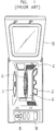
- FIG 1 is a front view of a known microwave oven.
- the known microwave oven includes a cooking chamber 10 in which food is cooked, a cooking chamber door 20 for providing access to the cooking chamber 10, a rotary motor (not illustrated), a rotary stand 11 connected with the rotary motor, and a tray 12 positioned on the rotary stand 11, and on which the food is placed for cooking.
- the known microwave oven also includes a heater 13 for grilling food, a thermistor 14 which senses the temperature of the cooking chamber 10, a control panel having a display 30 showing operational information of the microwave oven and a function selection part 40, a magnetron antenna (not shown) for supplying microwave energy to the cooking chamber 10 and which is mounted to an upper portion of a sidewall of the cooking chamber 10, and a magnetron (not shown) installed in a space at the rear of the display 30 for generating microwave energy and supplying it to the magnetron antenna.
- the heater 13 is mounted at the rear of the upper portion of the cooking chamber 10.
- the heater 13 is rotatable and is held in place by supporting members provided on the side walls of the cooking chamber 10.
- a cooking chamber lamp (not shown) is switched on to illuminate the cooking chamber 10, and the tray 11 rotates. Heat is produced when electricity is applied to the heater 13.
- the electricity applied to the heater 13 is shut off, and the heater 13 stops producing heat.
- the microwave oven informs the user.
- the know microwave oven with the heater 13 maintains a high temperature for a predetermined period of time even after the cooking time has finished. Since the known microwave oven has no means to measure the temperature of the heater 13, which falls slowly when power is removed, a user does not know how much hotter than the air in the cooking chamber 10 the heater 13 is. Thus, when a user tries to cook food with the known microwave oven before the heater 13 cools, he may touch the hot heater 13 as he either puts food into or takes food out of the cooking chamber 10. If his or her hand touches the heater 13, he or she may get burnt and instantaneously drop the food that he or she is holding, thus making the cooking chamber 10 dirty.
- a microwave oven according to the present invention is characterised by a temperature sensor for sensing the temperature of the heater element and alarm means responsive to opening of the door and the temperature sensor to produce an alarm signal if the temperature sensor indicates that the heater element is above a predetermined temperature when the door is being opened.
- a switch is used for detecting opening of the door.
- a piezoelectric element could be used instead.
- the temperature sensor preferably comprises a bimetal temperature sensor or a thermistor. If a thermistor is being used, the temperature sensor outputs a voltage related to the surface temperature of the heater element, a control unit compares this voltage with a reference voltage corresponding to a reference temperature, and controls the generation of the alarm.
- a microwave oven includes a heater temperature sensor 15 for checking the temperature of a heater 13, and this heater temperature sensor 15 is disposed on the cooking chamber 10's ceiling close to the heater 13.
- a function selection part 40 and display 30 are provided at the front of the microwave oven to allow a user to control the oven and confirm its operation with ease.
- the function selection part 40 has a cooking selection switch, a grill mode selection switch, and a power switch.
- the display 30 shows a user the control information programmed using the function selection part 40, and includes a visual alarm 50-1 which gives a user a warning if the temperature of the heater 13 is high when he or she opens a door 20 of the microwave oven.
- An audio alarm 50-2 such as a buzzer is provided at the bottom righthand corner of the display 30.
- Figure 3 is a circuit diagram of the inventive safety system, including the heater temperature sensor 15 for checking the temperature of the heater 13, and visual and audio alarms 50-1 and 50-2.
- the safety system includes a control unit 90 to which the heater temperature sensor 15 is coupled in series with a resistor R therebetween, and an alarm device 50 that is operated by an output signal of the control unit 90.
- the control unit 90 controls the alarm device 50 according to the value of the voltage output by the heater temperature sensor 15 that checks the temperature of the heater.
- a reference temperature for the heater temperature sensor 15 is set to 50°C.
- the reference temperature of the heater temperature sensor 15 is set to a value that will avoid a user from getting a burn when he or she touches the heater 13.
- the alarm device 50 consists of the visual alarm 50-1 and the audio alarm 50-2.
- the heater temperature sensor 15 is provided to the inside of the cooking chamber 10 for measuring the temperature of the heater 13. This is done with a thermistor, a temperature sensitive resistor.
- the thermistor has a high negative temperature coefficient of resistance, so that its resistance decreases as the temperature increases.
- the control unit 90 sounds the alarm device 50. If the temperature of the heater 13 drops to 50°C or less, the control unit 90 stops the alarm device 50. For example, once a constant voltage of 5V is applied across the heater temperature sensor 15 of 50°C, the control unit 90 detects a value of 2.5V or less. Accordingly, the control unit 90 compares the applied voltage with the preset voltage of 2.5V. If it determines that the applied voltage is lower than the preset voltage, it interprets that the temperature of the heater 13 is higher than the reference temperature, 50°C, and applies a driving signal to the alarm device 50.
- the heater temperature sensor's temperature If the temperature of the heater 13 decreases below the reference temperature, the heater temperature sensor's temperature also drops. Thus, the sensor's resistance decreases according to the drop in the heater temperature sensor's temperature, and the control unit 90 detects a voltage of 2.5V or over. The control unit 90 compares the applied voltage with the preset voltage of 2.5V, and if it determines that the applied voltage is higher than the preset voltage, it decides that the temperature of the heater 13 is lower than the reference temperature, 50°C, and does not operate the alarm device 50.
- the control unit 90 controls the power applied to the heater 13 so that the heater 13 produces heat.
- the display 30 shows the user the programmed control information on the function selection part 40.
- the power applied to the heater 13 is shut off so that the heater 13 and the user is informed that cooking has been completed. The user then removes the cooked food from the cooking chamber 10.
- the user may open the door 20 during cooking in order to inspect the cooking process or to bring the food out of the cooking chamber 10.
- control unit 90 detects the voltage of 2.5V or less, it determines (Step 300) that the temperature of the heater 13 is higher than the preset reference temperature (50°C) and sets the alarm device 50 off (Step 400). More specifically, the lamp of the display 30, the visual alarm device 50-1, is switched on, and the audio alarm device 50-1, the buzzer, is turned on. If a user puts his or her hand in the cooking chamber 10 in order to either take the food out of the cooking chamber 10 or put food in the cooking chamber 10, the alarm device 50 lets the user know that the heater 13 is still hot, thus preventing him or her from being burnt.
- control unit 90 it detects a voltage of greater than 2.5V, it determines that the temperature of the heater 13 is lower than the preset reference temperature (50°C) at Step 300, maintains the alarm device 50 in its off condition (Step 500), and then returns to the initial stage.
- control unit 90 determines that the temperature of the heater 13 is higher than the preset reference temperature (50′′C) at Step 300, and then returns to the initial stage with the alarm device turned on at Step 400, it continuously checks (Step 200) the temperature of the heater 13 periodically.
- the control unit 90 also compares (Step 300) the detected temperature with the preset reference temperature. if the control unit 90 determines that the detected temperature is lower than the preset reference temperature, it controls the power applied to the alarm device 50, thus stopping its operation (Step 500). In case that the control unit 90 determines that the detected temperature is higher than or equal to the preset reference temperature, it keeps operating the alarm device 50 (Step 400). As the control unit 90 senses that the door 20 is closed by the user, it controls the power applied across the alarm device 50, thus stopping its operation.
- a driver circuit for the safety system includes a bimetal sensor 151 serving to open and close its contact at a given point of temperature, and a door switch 70 sensing the opening and closing of the door 20, and an alarm device 50.
- the bimetal sensor 151 made of two laminas with different coefficients of thermal expansion, closes its contact to turn on the driver circuit for the safety system. If the temperature of the heater 13 goes down to a predetermined point and downward, the bimetal sensor 151 opens its contact to turn off the driver circuit.
- the door switch 70 is operated by a push button, and opening and closing the door 20 turns the driver circuit on and off.
- control unit 90 when the control unit 90 senses that the temperature of the heater 13 increases to a predetermined point and the door 20 is opened, it closes the'driver circuit to drive the alarm device 50. If the user opens the door 20 when the temperature of the heater 13 is higher than the predetermined point, the control unit 90 drives the alarm device 50 so that a warning is given to him or her.
- the extra heater temperature sensor is provided to a microwave oven for measuring the temperature of the heater only.
- the heater temperature sensor measures the temperature of the heater. If the measured heater temperature is high enough to burn the user if he or she touches the heater, the alarm device gives a warning to him or her when he or she puts a foodstuff in the cooking chamber or takes it out. In such a manner, the present invention prevents the user from being burnt by the hot heater.
Landscapes
- Physics & Mathematics (AREA)
- Electromagnetism (AREA)
- Electric Ovens (AREA)
- Electric Stoves And Ranges (AREA)
- Control Of High-Frequency Heating Circuits (AREA)
Applications Claiming Priority (2)
| Application Number | Priority Date | Filing Date | Title |
|---|---|---|---|
| KR1019970000602A KR19980065545A (ko) | 1997-01-11 | 1997-01-11 | 히터를 구비한 조리기기의 안전장치 |
| KR9700602 | 1997-01-11 |
Publications (2)
| Publication Number | Publication Date |
|---|---|
| EP0854661A2 true EP0854661A2 (fr) | 1998-07-22 |
| EP0854661A3 EP0854661A3 (fr) | 1999-01-07 |
Family
ID=19494488
Family Applications (1)
| Application Number | Title | Priority Date | Filing Date |
|---|---|---|---|
| EP97309544A Withdrawn EP0854661A3 (fr) | 1997-01-11 | 1997-11-26 | Four à micro-ondes avec dispositif de sécurité |
Country Status (4)
| Country | Link |
|---|---|
| US (1) | US5968402A (fr) |
| EP (1) | EP0854661A3 (fr) |
| JP (1) | JPH10205771A (fr) |
| KR (1) | KR19980065545A (fr) |
Cited By (3)
| Publication number | Priority date | Publication date | Assignee | Title |
|---|---|---|---|---|
| WO2002056640A3 (fr) * | 2001-01-11 | 2003-04-17 | Gen Electric | Four thermique/a convection comprenant des lampes halogenes |
| EP1635616A1 (fr) * | 2004-09-13 | 2006-03-15 | LG Electronics Inc. | Four à micro-ondes avec dispositif de chauffage rayonnant pivotant |
| CN105351983A (zh) * | 2015-12-15 | 2016-02-24 | 镇江市京口润明微波器械厂 | 一种防烫手微波炉 |
Families Citing this family (14)
| Publication number | Priority date | Publication date | Assignee | Title |
|---|---|---|---|---|
| US6677562B2 (en) * | 2001-03-13 | 2004-01-13 | Matsushita Electric Industrial Co., Ltd. | High-frequency heating apparatus and cooling system for magnetron-driving power supply utilized in the apparatus |
| KR100478455B1 (ko) | 2002-08-19 | 2005-03-22 | 삼성전자주식회사 | 전자렌지 |
| KR20040017188A (ko) * | 2002-08-20 | 2004-02-26 | 삼성전자주식회사 | 히터를 구비한 조리기 |
| KR20040017186A (ko) | 2002-08-20 | 2004-02-26 | 삼성전자주식회사 | 히터를 구비한 조리기 |
| CN100433944C (zh) * | 2003-02-21 | 2008-11-12 | 乐金电子(天津)电器有限公司 | 微波炉的温度和门感应电路 |
| KR100823296B1 (ko) * | 2003-03-28 | 2008-04-18 | 삼성전자주식회사 | 디스플레이 장치 |
| KR20040096201A (ko) * | 2003-05-07 | 2004-11-16 | 삼성전자주식회사 | 제빵기 및 그 제어방법 |
| US7244916B2 (en) | 2004-01-14 | 2007-07-17 | Sharp Kabushiki Kaisha | Microwave heating and cooking apparatus including drawer body |
| US7321309B2 (en) * | 2005-04-26 | 2008-01-22 | Kimberly-Clark Worldwide, Inc. | System for delivering pain without causing physiological damage |
| EP1754862A1 (fr) * | 2005-08-17 | 2007-02-21 | ABB Turbo Systems AG | Compresseur, roue de compresseur, accessoire de lavage et turbocompresseur d'échappement |
| US20110095016A1 (en) * | 2009-10-23 | 2011-04-28 | Standex International Corporation | Safe product transfer apparatus |
| KR101552888B1 (ko) * | 2013-12-19 | 2015-09-14 | 동부대우전자 주식회사 | 조리 기기의 제어 방법 및 그 장치 |
| JP7246355B2 (ja) * | 2017-07-07 | 2023-03-27 | ベクトン・ディキンソン・アンド・カンパニー | 医療用鋭利物取り外しデバイス用の誘導加熱回路 |
| US12474063B2 (en) | 2022-07-18 | 2025-11-18 | Whirlpool Corporation | Cooking appliance |
Family Cites Families (6)
| Publication number | Priority date | Publication date | Assignee | Title |
|---|---|---|---|---|
| NL165838C (nl) * | 1976-02-06 | 1981-05-15 | Haarlem Keramisch Inst | Keramiekoven. |
| JPS55119391A (en) * | 1979-03-06 | 1980-09-13 | Sharp Kk | Cooking oven |
| JPH03144217A (ja) * | 1989-10-27 | 1991-06-19 | Toshiba Corp | 加熱調理器 |
| US5528018A (en) * | 1991-08-19 | 1996-06-18 | Henny Penny Corporation | Programmable load compensation method and apparatus for use in a food |
| JPH0571745A (ja) * | 1991-09-10 | 1993-03-23 | Toshiba Corp | 加熱調理器 |
| JPH08261479A (ja) * | 1995-03-22 | 1996-10-11 | Sanyo Electric Co Ltd | 調理器 |
-
1997
- 1997-01-11 KR KR1019970000602A patent/KR19980065545A/ko not_active Ceased
- 1997-11-26 EP EP97309544A patent/EP0854661A3/fr not_active Withdrawn
- 1997-11-28 JP JP9328646A patent/JPH10205771A/ja active Pending
- 1997-12-11 US US08/989,003 patent/US5968402A/en not_active Expired - Fee Related
Cited By (3)
| Publication number | Priority date | Publication date | Assignee | Title |
|---|---|---|---|---|
| WO2002056640A3 (fr) * | 2001-01-11 | 2003-04-17 | Gen Electric | Four thermique/a convection comprenant des lampes halogenes |
| EP1635616A1 (fr) * | 2004-09-13 | 2006-03-15 | LG Electronics Inc. | Four à micro-ondes avec dispositif de chauffage rayonnant pivotant |
| CN105351983A (zh) * | 2015-12-15 | 2016-02-24 | 镇江市京口润明微波器械厂 | 一种防烫手微波炉 |
Also Published As
| Publication number | Publication date |
|---|---|
| US5968402A (en) | 1999-10-19 |
| JPH10205771A (ja) | 1998-08-04 |
| KR19980065545A (ko) | 1998-10-15 |
| EP0854661A3 (fr) | 1999-01-07 |
Similar Documents
| Publication | Publication Date | Title |
|---|---|---|
| EP0854661A2 (fr) | Four à micro-ondes avec dispositif de sécurité | |
| US4874928A (en) | A heating apparatus for automatically distinguishing the condition of food to be reheated | |
| KR100306552B1 (ko) | 데몬스트레이션모드를구비한요리장치 | |
| US5545880A (en) | Method for automatic control of a microwave oven | |
| GB2033108A (en) | Controlling heating apparatus | |
| JPH0781713B2 (ja) | 電子レンジ | |
| US5595673A (en) | Microwave oven with microwave-actuable bottom and temperature sensor | |
| CN1188212A (zh) | 用于具有加热器的微波炉的安全系统 | |
| JP4735276B2 (ja) | 高周波加熱装置 | |
| CN103080655A (zh) | 高频加热装置 | |
| JP3022338B2 (ja) | 電気炊飯器 | |
| KR0154646B1 (ko) | 전자렌지의 조리진행에 따른 도어 오픈상태 알림방법 | |
| JPH08312966A (ja) | 加熱調理器 | |
| JP7795369B2 (ja) | 加熱調理器 | |
| JPS61262526A (ja) | 加熱器 | |
| KR0146131B1 (ko) | 마이크로웨이브오븐의 자동조리 장치 및 방법 | |
| JP2518127B2 (ja) | 高周波加熱調理装置 | |
| JPS5828499B2 (ja) | ヒ−タ付電子レンジ | |
| KR970006078B1 (ko) | 마이크로웨이브오븐의 자동조리 제어방법 | |
| JPH06338388A (ja) | 電子レンジ | |
| KR100499478B1 (ko) | 토스터 겸용 전자레인지 및 그 제어방법 | |
| JP3008389B2 (ja) | 調理器 | |
| JP3246202B2 (ja) | 高周波加熱器 | |
| JP2024022270A (ja) | 電子レンジ | |
| KR100939719B1 (ko) | 토스터의 요리 제어방법 |
Legal Events
| Date | Code | Title | Description |
|---|---|---|---|
| PUAI | Public reference made under article 153(3) epc to a published international application that has entered the european phase |
Free format text: ORIGINAL CODE: 0009012 |
|
| AK | Designated contracting states |
Kind code of ref document: A2 Designated state(s): AT BE CH DE DK ES FI FR GB GR IE IT LI LU MC NL PT SE |
|
| AX | Request for extension of the european patent |
Free format text: AL;LT;LV;MK;RO;SI |
|
| PUAL | Search report despatched |
Free format text: ORIGINAL CODE: 0009013 |
|
| AK | Designated contracting states |
Kind code of ref document: A3 Designated state(s): AT BE CH DE DK ES FI FR GB GR IE IT LI LU MC NL PT SE |
|
| AX | Request for extension of the european patent |
Free format text: AL;LT;LV;MK;RO;SI |
|
| AKX | Designation fees paid | ||
| STAA | Information on the status of an ep patent application or granted ep patent |
Free format text: STATUS: THE APPLICATION IS DEEMED TO BE WITHDRAWN |
|
| 18D | Application deemed to be withdrawn |
Effective date: 19990708 |
|
| REG | Reference to a national code |
Ref country code: DE Ref legal event code: 8566 |