EP0855002B1 - Support - Google Patents
Support Download PDFInfo
- Publication number
- EP0855002B1 EP0855002B1 EP96934667A EP96934667A EP0855002B1 EP 0855002 B1 EP0855002 B1 EP 0855002B1 EP 96934667 A EP96934667 A EP 96934667A EP 96934667 A EP96934667 A EP 96934667A EP 0855002 B1 EP0855002 B1 EP 0855002B1
- Authority
- EP
- European Patent Office
- Prior art keywords
- compensating
- weight
- load
- arm
- stand
- Prior art date
- Legal status (The legal status is an assumption and is not a legal conclusion. Google has not performed a legal analysis and makes no representation as to the accuracy of the status listed.)
- Expired - Lifetime
Links
- 238000005259 measurement Methods 0.000 claims description 37
- 238000006073 displacement reaction Methods 0.000 claims description 24
- 230000008859 change Effects 0.000 claims description 14
- 238000000034 method Methods 0.000 claims description 12
- 230000005484 gravity Effects 0.000 claims description 8
- 230000003287 optical effect Effects 0.000 claims description 8
- 239000000725 suspension Substances 0.000 claims description 6
- 230000005540 biological transmission Effects 0.000 claims description 5
- 230000008878 coupling Effects 0.000 claims description 4
- 238000010168 coupling process Methods 0.000 claims description 4
- 238000005859 coupling reaction Methods 0.000 claims description 4
- 230000001419 dependent effect Effects 0.000 claims description 3
- 230000003068 static effect Effects 0.000 claims description 3
- OKTJSMMVPCPJKN-UHFFFAOYSA-N Carbon Chemical compound [C] OKTJSMMVPCPJKN-UHFFFAOYSA-N 0.000 claims description 2
- 229920000271 Kevlar® Polymers 0.000 claims description 2
- 239000004760 aramid Substances 0.000 claims description 2
- 229910052799 carbon Inorganic materials 0.000 claims description 2
- 239000004761 kevlar Substances 0.000 claims description 2
- 229920002430 Fibre-reinforced plastic Polymers 0.000 claims 1
- 229920003235 aromatic polyamide Polymers 0.000 claims 1
- 230000001447 compensatory effect Effects 0.000 claims 1
- 230000006835 compression Effects 0.000 claims 1
- 238000007906 compression Methods 0.000 claims 1
- 239000003365 glass fiber Substances 0.000 claims 1
- 230000005389 magnetism Effects 0.000 claims 1
- 238000004377 microelectronic Methods 0.000 claims 1
- 239000011208 reinforced composite material Substances 0.000 claims 1
- 238000005096 rolling process Methods 0.000 claims 1
- 238000005452 bending Methods 0.000 description 22
- 230000006870 function Effects 0.000 description 13
- 230000008901 benefit Effects 0.000 description 8
- 239000000243 solution Substances 0.000 description 8
- 238000011161 development Methods 0.000 description 7
- 230000018109 developmental process Effects 0.000 description 7
- 230000008569 process Effects 0.000 description 7
- 238000010586 diagram Methods 0.000 description 5
- 230000000694 effects Effects 0.000 description 5
- 230000002829 reductive effect Effects 0.000 description 5
- 241000238633 Odonata Species 0.000 description 4
- 238000010276 construction Methods 0.000 description 4
- 238000004519 manufacturing process Methods 0.000 description 4
- 239000000463 material Substances 0.000 description 4
- 239000002131 composite material Substances 0.000 description 3
- 230000006378 damage Effects 0.000 description 3
- 238000013461 design Methods 0.000 description 3
- 230000001960 triggered effect Effects 0.000 description 3
- 208000027418 Wounds and injury Diseases 0.000 description 2
- 238000001514 detection method Methods 0.000 description 2
- 238000009826 distribution Methods 0.000 description 2
- 238000005516 engineering process Methods 0.000 description 2
- 239000000835 fiber Substances 0.000 description 2
- 230000006872 improvement Effects 0.000 description 2
- 208000014674 injury Diseases 0.000 description 2
- 239000007788 liquid Substances 0.000 description 2
- 238000000691 measurement method Methods 0.000 description 2
- 230000007246 mechanism Effects 0.000 description 2
- 230000007935 neutral effect Effects 0.000 description 2
- 230000036961 partial effect Effects 0.000 description 2
- 230000009467 reduction Effects 0.000 description 2
- 238000000926 separation method Methods 0.000 description 2
- 238000012549 training Methods 0.000 description 2
- 229920000049 Carbon (fiber) Polymers 0.000 description 1
- 241000408529 Libra Species 0.000 description 1
- 229920005830 Polyurethane Foam Polymers 0.000 description 1
- 230000009471 action Effects 0.000 description 1
- 239000000853 adhesive Substances 0.000 description 1
- 230000001070 adhesive effect Effects 0.000 description 1
- 230000002411 adverse Effects 0.000 description 1
- 229920006231 aramid fiber Polymers 0.000 description 1
- 244000052616 bacterial pathogen Species 0.000 description 1
- 230000000903 blocking effect Effects 0.000 description 1
- 230000037396 body weight Effects 0.000 description 1
- 239000004917 carbon fiber Substances 0.000 description 1
- 239000000969 carrier Substances 0.000 description 1
- 239000003795 chemical substances by application Substances 0.000 description 1
- 238000005352 clarification Methods 0.000 description 1
- 239000011248 coating agent Substances 0.000 description 1
- 238000000576 coating method Methods 0.000 description 1
- 238000011109 contamination Methods 0.000 description 1
- 238000001816 cooling Methods 0.000 description 1
- 230000003247 decreasing effect Effects 0.000 description 1
- 239000000645 desinfectant Substances 0.000 description 1
- 230000005281 excited state Effects 0.000 description 1
- 239000006260 foam Substances 0.000 description 1
- 238000002347 injection Methods 0.000 description 1
- 239000007924 injection Substances 0.000 description 1
- 238000009434 installation Methods 0.000 description 1
- 239000012774 insulation material Substances 0.000 description 1
- 210000003127 knee Anatomy 0.000 description 1
- 239000000696 magnetic material Substances 0.000 description 1
- 239000002184 metal Substances 0.000 description 1
- 238000012544 monitoring process Methods 0.000 description 1
- 238000004091 panning Methods 0.000 description 1
- 239000011295 pitch Substances 0.000 description 1
- 239000004033 plastic Substances 0.000 description 1
- 229920003023 plastic Polymers 0.000 description 1
- 239000011496 polyurethane foam Substances 0.000 description 1
- 238000003825 pressing Methods 0.000 description 1
- 230000001105 regulatory effect Effects 0.000 description 1
- 238000004904 shortening Methods 0.000 description 1
- 238000003860 storage Methods 0.000 description 1
- 230000007704 transition Effects 0.000 description 1
Images






Classifications
-
- G—PHYSICS
- G02—OPTICS
- G02B—OPTICAL ELEMENTS, SYSTEMS OR APPARATUS
- G02B7/00—Mountings, adjusting means, or light-tight connections, for optical elements
- G02B7/001—Counterbalanced structures, e.g. surgical microscopes
-
- F—MECHANICAL ENGINEERING; LIGHTING; HEATING; WEAPONS; BLASTING
- F16—ENGINEERING ELEMENTS AND UNITS; GENERAL MEASURES FOR PRODUCING AND MAINTAINING EFFECTIVE FUNCTIONING OF MACHINES OR INSTALLATIONS; THERMAL INSULATION IN GENERAL
- F16M—FRAMES, CASINGS OR BEDS OF ENGINES, MACHINES OR APPARATUS, NOT SPECIFIC TO ENGINES, MACHINES OR APPARATUS PROVIDED FOR ELSEWHERE; STANDS; SUPPORTS
- F16M11/00—Stands or trestles as supports for apparatus or articles placed thereon ; Stands for scientific apparatus such as gravitational force meters
- F16M11/02—Heads
- F16M11/04—Means for attachment of apparatus; Means allowing adjustment of the apparatus relatively to the stand
- F16M11/06—Means for attachment of apparatus; Means allowing adjustment of the apparatus relatively to the stand allowing pivoting
- F16M11/10—Means for attachment of apparatus; Means allowing adjustment of the apparatus relatively to the stand allowing pivoting around a horizontal axis
-
- F—MECHANICAL ENGINEERING; LIGHTING; HEATING; WEAPONS; BLASTING
- F16—ENGINEERING ELEMENTS AND UNITS; GENERAL MEASURES FOR PRODUCING AND MAINTAINING EFFECTIVE FUNCTIONING OF MACHINES OR INSTALLATIONS; THERMAL INSULATION IN GENERAL
- F16M—FRAMES, CASINGS OR BEDS OF ENGINES, MACHINES OR APPARATUS, NOT SPECIFIC TO ENGINES, MACHINES OR APPARATUS PROVIDED FOR ELSEWHERE; STANDS; SUPPORTS
- F16M11/00—Stands or trestles as supports for apparatus or articles placed thereon ; Stands for scientific apparatus such as gravitational force meters
- F16M11/20—Undercarriages with or without wheels
- F16M11/2007—Undercarriages with or without wheels comprising means allowing pivoting adjustment
- F16M11/2035—Undercarriages with or without wheels comprising means allowing pivoting adjustment in more than one direction
- F16M11/2064—Undercarriages with or without wheels comprising means allowing pivoting adjustment in more than one direction for tilting and panning
-
- F—MECHANICAL ENGINEERING; LIGHTING; HEATING; WEAPONS; BLASTING
- F16—ENGINEERING ELEMENTS AND UNITS; GENERAL MEASURES FOR PRODUCING AND MAINTAINING EFFECTIVE FUNCTIONING OF MACHINES OR INSTALLATIONS; THERMAL INSULATION IN GENERAL
- F16M—FRAMES, CASINGS OR BEDS OF ENGINES, MACHINES OR APPARATUS, NOT SPECIFIC TO ENGINES, MACHINES OR APPARATUS PROVIDED FOR ELSEWHERE; STANDS; SUPPORTS
- F16M11/00—Stands or trestles as supports for apparatus or articles placed thereon ; Stands for scientific apparatus such as gravitational force meters
- F16M11/42—Stands or trestles as supports for apparatus or articles placed thereon ; Stands for scientific apparatus such as gravitational force meters with arrangement for propelling the support stands on wheels
-
- F—MECHANICAL ENGINEERING; LIGHTING; HEATING; WEAPONS; BLASTING
- F21—LIGHTING
- F21L—LIGHTING DEVICES OR SYSTEMS THEREOF, BEING PORTABLE OR SPECIALLY ADAPTED FOR TRANSPORTATION
- F21L14/00—Electric lighting devices without a self-contained power source, e.g. for mains connection
- F21L14/04—Electric lighting devices without a self-contained power source, e.g. for mains connection carried on wheeled supports
-
- F—MECHANICAL ENGINEERING; LIGHTING; HEATING; WEAPONS; BLASTING
- F21—LIGHTING
- F21V—FUNCTIONAL FEATURES OR DETAILS OF LIGHTING DEVICES OR SYSTEMS THEREOF; STRUCTURAL COMBINATIONS OF LIGHTING DEVICES WITH OTHER ARTICLES, NOT OTHERWISE PROVIDED FOR
- F21V21/00—Supporting, suspending, or attaching arrangements for lighting devices; Hand grips
- F21V21/06—Bases for movable standing lamps; Fixing standards to the bases
-
- A—HUMAN NECESSITIES
- A61—MEDICAL OR VETERINARY SCIENCE; HYGIENE
- A61B—DIAGNOSIS; SURGERY; IDENTIFICATION
- A61B90/00—Instruments, implements or accessories specially adapted for surgery or diagnosis and not covered by any of the groups A61B1/00 - A61B50/00, e.g. for luxation treatment or for protecting wound edges
- A61B90/50—Supports for surgical instruments, e.g. articulated arms
- A61B2090/5025—Supports for surgical instruments, e.g. articulated arms with a counter-balancing mechanism
- A61B2090/504—Supports for surgical instruments, e.g. articulated arms with a counter-balancing mechanism with a counterweight
-
- A—HUMAN NECESSITIES
- A61—MEDICAL OR VETERINARY SCIENCE; HYGIENE
- A61B—DIAGNOSIS; SURGERY; IDENTIFICATION
- A61B90/00—Instruments, implements or accessories specially adapted for surgery or diagnosis and not covered by any of the groups A61B1/00 - A61B50/00, e.g. for luxation treatment or for protecting wound edges
- A61B90/50—Supports for surgical instruments, e.g. articulated arms
- A61B2090/506—Supports for surgical instruments, e.g. articulated arms using a parallelogram linkage, e.g. panthograph
-
- A—HUMAN NECESSITIES
- A61—MEDICAL OR VETERINARY SCIENCE; HYGIENE
- A61B—DIAGNOSIS; SURGERY; IDENTIFICATION
- A61B90/00—Instruments, implements or accessories specially adapted for surgery or diagnosis and not covered by any of the groups A61B1/00 - A61B50/00, e.g. for luxation treatment or for protecting wound edges
- A61B90/20—Surgical microscopes characterised by non-optical aspects
-
- F—MECHANICAL ENGINEERING; LIGHTING; HEATING; WEAPONS; BLASTING
- F16—ENGINEERING ELEMENTS AND UNITS; GENERAL MEASURES FOR PRODUCING AND MAINTAINING EFFECTIVE FUNCTIONING OF MACHINES OR INSTALLATIONS; THERMAL INSULATION IN GENERAL
- F16M—FRAMES, CASINGS OR BEDS OF ENGINES, MACHINES OR APPARATUS, NOT SPECIFIC TO ENGINES, MACHINES OR APPARATUS PROVIDED FOR ELSEWHERE; STANDS; SUPPORTS
- F16M2200/00—Details of stands or supports
- F16M2200/04—Balancing means
- F16M2200/041—Balancing means for balancing rotational movement of the head
-
- F—MECHANICAL ENGINEERING; LIGHTING; HEATING; WEAPONS; BLASTING
- F16—ENGINEERING ELEMENTS AND UNITS; GENERAL MEASURES FOR PRODUCING AND MAINTAINING EFFECTIVE FUNCTIONING OF MACHINES OR INSTALLATIONS; THERMAL INSULATION IN GENERAL
- F16M—FRAMES, CASINGS OR BEDS OF ENGINES, MACHINES OR APPARATUS, NOT SPECIFIC TO ENGINES, MACHINES OR APPARATUS PROVIDED FOR ELSEWHERE; STANDS; SUPPORTS
- F16M2200/00—Details of stands or supports
- F16M2200/04—Balancing means
- F16M2200/044—Balancing means for balancing rotational movement of the undercarriage
-
- F—MECHANICAL ENGINEERING; LIGHTING; HEATING; WEAPONS; BLASTING
- F21—LIGHTING
- F21W—INDEXING SCHEME ASSOCIATED WITH SUBCLASSES F21K, F21L, F21S and F21V, RELATING TO USES OR APPLICATIONS OF LIGHTING DEVICES OR SYSTEMS
- F21W2131/00—Use or application of lighting devices or systems not provided for in codes F21W2102/00-F21W2121/00
- F21W2131/20—Lighting for medical use
Definitions
- the desired weight balance is based on the theory that an optimal weight balance can only be achieved if Load application point, main pivot point and center of gravity of the or all Balance weights (s) lie on a straight line. This theory is better explained or apparent in the more recent EP-A-656 194.
- DE-A1-43 20 443 gives a semi-automatic - in that respect too can be operated with a tripod, but with a different weight distribution from two adjustable weights is provided. Furthermore, the structure according to this document on balancing in a specific position of the Tripods restricted. In addition, X-Y adjustments of the load are mandatory (Surgical microscope) provided. In the course of the further development of Invention are also improvements over this known structure realized.
- the embodiment aims at a tripod with fully automatic adjustment of the Balance.
- the use of the new tripod is not restricted.
- the optical range of near and far magnifications is included.
- the invention provides that forces or Moments resulting from the imbalance are measured by one to be able to make targeted adjustments to the balance weight or weights.
- the Balance weight is shifted according to the invention to that position in which the measured value of the forces or moments resulting from the imbalance is almost zero. These do not necessarily have to be absolute values (absolutely zero) it can also be relative values. For example with a Bending measurement on a load arm can be a specific one when unloaded Bending moment can be determined, which increases by increasing the load.
- the Adjustment of the balance weight is according to the size the bending moment difference between unloaded and loaded condition controlled or triggered. According to an embodiment of the invention a big difference in the measured values a quick adjustment of the Balance weight or balance weights; only minor imbalances on the other hand cause a slight feed rate of the Balance weight.
- the targeted control of the balance weight can be done on the one hand by e.g. light-optical, bar-coded position encoders or distance meters on Compensation arm or also by rotation monitoring of the drive spindle be realized for the counterweight.
- Exact knowledge of the position of the Balance weight before starting a measurement with this variant can be done by automatic zero adjustment of the system (counterweight moves automatically to a certain position after switching on the system) or can be accomplished on the fly by the current position of the Balance weight determined in relation to a fixed point on the balance arm becomes.
- Those provided according to the invention are particularly advantageous Measuring devices constructed as torque measuring devices, which in Range of any axes of the tripod can be accommodated, provided on these axes two components are mounted, which are dependent on the Try to imbalance to perform a swiveling movement to each other. Because on these points can be the force generating the pivoting movement (the Imbalance) e.g. be measured as torque.
- a brake is activated, which pivots the parts blocked to each other.
- the forces that the brake has to absorb correspond to the torques sought. They are in an unbalanced state Torsional forces on the brake zero. In other words, it takes place like this according to the invention, a comparison measurement of the resulting torques from the bending moments of the load and the bending moment of the Balance weight instead.
- the forces on the brake are via a Measuring arm that is torsionally rigid with one of the two swiveling parts connected or braked, transmitted to the outside and from a rigid Support the other of the two parts intercepted.
- the ones on Measuring arm resulting bend, which is proportional to the torsion, is directly or measured indirectly on the measuring arm. Strain gauge elements are preferred for this purpose to use.
- the Measuring arm also have a slight play in relation to the stop, so that small swivel movements still take place without measured values, while on the other hand, possibly depending on the size of the measured values different adjustment process of the balancing weights or triggered can be.
- a microswitch or the like is operated so that in the event of excessive imbalance (e.g. a Surgeon stumbles and briefly captures his body weight at the microscope) the balance weight is immediately moved to a new balance position.
- a microswitch can also be spring-loaded and / or be biased.
- bends that occur due to the load on the load arm can also occur directly can be measured by using strain gauge elements directly on the load arm or be applied to the balance arm.
- Balance measurements with one Light-optical spirit levels of a spirit level are not for measurements in the braked state also conceivable.
- a ray of light is through a dark one Steamed liquid of a dragonfly. Only on the air bubble or the like. can light shine through well.
- a flat light sensor is located behind the dragonfly, which thus capture the status of the air bubble and send it to the appropriate Controls can forward.
- composite measurement methods are also within the scope of the invention, where e.g. at one point on the base of the tripod the vertical Weight vector of the tripod or a part thereof is measured while at the same time e.g. the angular position of the load arm relative to the vertical is measured to determine the weight or weight change of the Load that influences the weight vector at the measuring point as a component, recalculated.
- the measurement takes place and / or shift of the counterweight takes place with a time delay.
- Operator places a hand on the load (microscope) and this too remains there shortly after the load change, or an operator after he has the released the tripod's electrical brakes and put them back on with his Hands still holding the microscope so that the weight of the hands does that could falsify the measurement result.
- Another inventive aspect of the application is the choice of one new advantageous material for the tripod.
- the disadvantage with conventional Tripods are in a relatively voluminous design, which is relative to one high overall weight with reasonable strength of the tripod and thus a appropriate load on the floor or ceiling (depending on the installation site) leads.
- Another disadvantage of the known tripods is the space requirement for load and balance arms because of their geometric dimensions restrict a user's scope of work.
- Parts of the tripod to reduce the weight and increase its strength sintered or glued - preferably not epoxy-bonded - fiber composite material e.g. made of carbon or carbon fibers, aramid fibers or Kevlar (registered trademark of the Du Pont company); in particular this affects the load and / or balance arm.
- the composite materials used depend on their structuring (fiber layer) which can be set as desired to the advantages mentioned lead and also positively influence the vibration behavior of the components, so that the tripod can be positioned more directly.
- Carriers of the tripod are formed in two parts and lying in parallel, see above that a space is created between them in which the cables are laid can, the space being covered by removable cover plates.
- Another aspect is another protection or cable duct for the Load - usually to the microscope - leading cable that is independent, but also useful in combination with the cable duct just mentioned can be applied.
- a flexible hose e.g. a corrugated hose, which at its entrance and preferably also at its output is provided with a rotatable coupling, so that one Rotation of the load arm around a vertical axis of the corrugated hose Has the possibility to take part in the rotation to a certain extent so that the Hose is not subjected to torsion.
- the advantage of this new cable routing therefore lies in particular in protecting the cable from mechanical External loads and injuries to the cables.
- the use of the hose reduces the risk of unwanted contamination of the cable with germs or the like.
- the hose can be disinfected more easily than previously the cables become. It can easily be made from a material that is attached to its Treat the surface generously with liquid disinfectant can what under certain insulation materials for the cables used Circumstances is problematic.
- hose used can be dispensed with, since an applicable product is known per se and is based on the Market is.
- An example is the NW Duplex or Duplex-SVPA corrugated hose referenced, which is offered by the Rohrfabrik Rüschlikon AG.
- Another aspect of the invention is particularly in an operating microscope on the guidance or mounting of the same in the area of the load attack directed.
- tripod from Mitaka and with all Conventional tripods were tried in principle the focus to achieve that the actual microscope guided left and is adjustable on the right to get into the center of gravity, namely not just left and right, but also forward and backward.
- levels of adjustment slides here, their adjustment by operating personnel is relatively complex and expensive.
- Another aspect of the invention relates to the problem of Transport of tripods with relatively large and protruding arms.
- tripods are supported on wheels by stands and feet.
- a Fixation against the floor is traditionally done by blocking the Wheels or a lowering of adjustable feet or the like.
- DE-U-84 00 384 When moving the tripod it is traditionally rolled on its wheels.
- the load or compensating arms have already been able to move into one position be pivoted, which reduced the space requirement of the tripod, but is one Improvement desirable.
- this problem is solved by the constructive possibility lowering the stand of the tripod or the arms on the tripod the stand and / or the lowerability of at least one of the feet supporting wheels, so that the tripod is tilted during transport, the if necessary, further reduce its transport height and center of gravity.
- the size of the tripod is also determined by the Size of its components and the number of individual components required. So far, the tripod was rotatable about the vertical axis mentioned two bearings each lying in a horizontal plane are required, which the Needed a tubular sleeve that brought the bearings and contained the stand in it. Since the sleeve itself has nothing to do with strength vertical direction, but contributed to the tipping moment power transmission unbalanced tripod, she had to be massive and therefore be difficult to train. Reducing the sleeve diameter and the replacement of ball bearings with a normal plain bearing brought one small diameter reduction of the stator, but increased the friction and thus reduced ease of use.
- the new inventive solution provides for the stand by means of a cross roller bearing against the foot, which above all regarding the low speed of the tripod around its vertical axis can be used optimally and without wear.
- the crossed roller bearing is can be easily integrated into the base of the tripod due to its low overall height and that Tripod thus freely and freely rotatable around its vertical axis.
- the space requirement of the stand is further reduced compared to the known one.
- Another aspect of the invention relates to electromagnetic brakes in the joints of the tripod to apply to the arms or To fix arm parts relative to each other.
- a known brake is exemplified in of the aforementioned EP-A-656 194 shown in Figs. 12 and 13. Pressure springs press brake discs against a counterpart, so this is jammed between two brake discs. On one side one Brake disc is an electromagnet mounted, which in the excited state Brake disc attracts and thus releases the counterpart. After switching off the The brake disc is braked electromagnetically by the spring force pushed the counterpart. A collision with this results in a Relatively loud noise that is annoying in an operating room can be.
- a brake for the joints of the tripod provided that is less noisy with good braking properties. This will in that the electromagnet is not suddenly, but gradually is de-energized so that the brake disc is braked by the spring force against the Counterpart is pushed.
- An improved variant provides that instead of the spring for Pressing the brake disc a permanent magnet is provided, which in de-energized state keeps the brake braked.
- the advantage of this construction compared to the known is the even better, noiseless controllability of the Braking process and the reduction of moving, wear underlying parts, namely the springs.
- Another aspect of the invention relates to the simplification of the tripod components. While conventional tripods have a variety of different components have, which are each assigned a special function provided according to the invention, at least the load arm and the support arm vertical swivel arm to be identical, so that in series production can be saved. An average C-shaped structure of these parts causes one accordingly large free working zone for the users. The new geometry has also had an advantageous effect on the ability to balance. In the Description of the figures is referred to other identical components.
- a Swivel axis 9 through which a load and balance arm from a horizontal Level 63 can be pivoted.
- One by an adjustment device 7 Slidable balance weight 5 tries a load 3 over the axis 9 balance.
- the displacement device 7 is by Measured values controlled, which can be obtained in measuring devices 6 a-f. These are measuring devices which, depending on the location and type of Assembling bends 6a, e, f, trains or pressures 6b, c or e, or Measure torques 6d and feed them back to the shifting device.
- any of the mentioned measurement values can be added are used, any changes in weight of the load 3 on the Determine load suspension 8 and the counterweight 5 accordingly to postpone.
- additional information is required to the Activate shifting device 7 correctly. This information can For example, be: Before changing the load, knowledge of the balanced position the counterweight 5.
- Bending moment measurements in the area of the stand 6a, e therefore require no additional information than the shift of the counterweight 5 only has to be reduced so that the bending moments are close to zero go.
- Designated swivel stand. 1 it is conceivable that Swiveling between stand 1 and swivel stand 40 by one Spring balancer or the like manufacture so that the swivel stand 40 by a not shown spring inside the stand 1 in its desired position in Angle to the vertical or is kept out of a vertical plane 64.
- FIG. 2 a preferred variant is shown in FIG. 2, where a Swivel stand 40 freely on the stand 1 about a vertical swivel axis 18 is pivoted.
- a part 40a serves as a load part, the Horizontal pivot axis 9 and the load and balance arm 2a, 4a carries and a balance arm 40b which carries a balance weight 5b which the Swivel stand 40 above the vertical swivel axis 18 in balance with the Balance weight 5a, the load and the weight of the arms 2a and 4a holds.
- This symbolically represented tripod provides the mechanical separate function of horizontal and vertical panning around horizontal and vertical planes 63 and 64.
- FIG. 3 shows a pivot axis 9A, which is basically the Swiveling the load arm 2 relative to the stand 1 allowed.
- a brake 10a which in the braked state Axis 9a blocked and pivoting blocked.
- the measuring device 6d1 also represents an angle measuring device that can be used for alternative measurement methods: For example the angular position between the load arm 2 and the stand 1 and the pressure in measured by a measuring device 6c (FIG. 1), these two values can be used inferred about the size of the load or load change and accordingly an adjustment of the counterweight 5 can be made.
- the variant according to FIG. 4 relates to a basic structure according to FIG. 2 with swiveling in both horizontal and vertical plane.
- the Swivel stand 40 is fixed with one in this form of training Angle extension 40b1 connected, which carries a counterweight 5b.
- On Swiveling the swivel stand 40 out of the vertical plane 64 is possible the balance weight 5b being the balance with that of the swivel stand 40 manufactures worn components.
- the Measuring device 6d3 a bending moment on a bending beam Braking device 10b measured.
- a symbolically represented calculator or Computer 14 evaluates the measurement result of 6d3 and controls one Drive 11a of the displacement device 7a on the compensating arm 4 and on the other hand the drive 11b on the compensating arm 40b1.
- this connection is in Computer 14 takes into account so that a single measurement is related sufficient with the balance over the horizontal swivel plane, also a automatic balancing for pivoting movements according to the invention perform from the vertical swivel plane.
- FIG. 5 A variant of Figure 3 is shown in Figure 5, where a bending beam 66 one Measuring device 6d2 is loaded on the bend as soon as the brake 10a on a driver part 67 is mounted, brakes it on the shaft 9a.
- a display 13 on which the imbalance is read is indicated symbolically can be.
- Variants are also included in the scope of the invention which the information about the unbalance of an operator visually or be communicated acoustically to enable manual balancing.
- the symbolic structure according to FIG. 6 uses known ones Parallelogram steering arms for the static transmission of loads or forces and balancing forces.
- Fig. 6 also shows one Special feature according to the invention in the area of the foot 23: a transport handle 30 with a handle bar 31 allows the tripod to be moved in one Preferred direction according to arrow 27a. To make transportation easier is beyond symbolically represented by arrow 27b that the wheel 25a opposite the foot 23 can be lowered or retracted, cf. the symbolically represented Adjustment mechanism 26. Retraction of the wheel 25a leads to an easy one Tilting the tripod backwards so that it is good for an operator can be held and pushed. Tilting also reduces something the overall height, provided that the load arm 2 is pivoted downwards.
- the symbolically represented option also serves to facilitate transportation the lowering of the stand 1e relative to a sleeve 28 which is connected to the foot 23 is rigidly connected, cf. the arrow 27c.
- a symbolic locking button 29 allows locking in the desired height position.
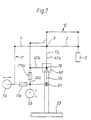
- the variant according to Figure 7 corresponds to the principle of Figure 2 in that one complete separation between vertical and horizontal swivel movement is made.
- the swivel stand 40 carries with its compensating arm 40b the counterweight 5b, which is only about the vertical pivot axis 18 together with a corresponding swiveling movement of the swivel stand 40 is possible.
- the load arm 2 with the compensating arm 4 or of the associated parallelogram link 15 and 17 designed so that a 15 and 17 pivot about the horizontal pivot axis 9 regardless of Swivel stand 40 is possible.
- a part of the parallelogram 17 is in the Representation congruent with part 40a.
- the measurement options provided in this example are exemplary and shown as an alternative with measuring device 6d or 6h.
- a measuring device 6, which may be a Position detection device 68 includes, measures unbalance parameters.
- the Measured values are fed to a controller 14 which, on the one hand, makes calculations executes and on the other hand issues adjustment commands.
- Over a Adjustment device 7a is the position of the counterweight 5a directly adjusted.
- the adjustment value leading to this adjustment is in the control 14 using tables or formulas for an adjustment value for the Balance weight 5b converted by an adjusting device 7b is realized.
- Fig. 9 What is special and inventive about the subject of Fig. 9 is, among other things.
- the cross bearing 24 thus forms the pivot bearing 34 for the rotatability of the Tripods around a vertical axis.
- Wheels 25a and 25b are rotatable wheels shown. However, only one wheel or a pair of wheels around a vertical is preferred Axis swiveling while another wheel or a different pair of wheels in the In the sense of a preferred direction of displacement is rigid.
- a braking device 10c is provided in the area of the rotary bearing 34 is electrically detachable via a supply line 32.
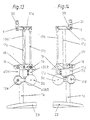
- Fig. 10 shows a housing 33 for the foot 23 again.
- a parallelogram guide 17 with individually labeled components 17a-f carries the counterweight 5a and a measuring device 6h.
- a swivel stand 40 with parallelogram guide 40b carries the counterweight 5b.
- a bearing block 35 and associated arms 2d and e as well as 40a1 and 40a2 secure all Swiveling movements the vertical position of the load suspension 8.
- a swivel head 1b which is the main supporting part on a pivot bearing 34 on the stand 1a sits, holds the two swivel stand arms 40a1 by means of an invisible axis and 40a2 in position.
- 40a1 and 40a2 could also be made as a single piece be formed, as well as the two arm parts 2d and 2e. According to the invention However, these are divided into two, on the one hand to reduce the overall depth and on the other hand to create the cable duct according to the invention.
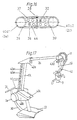
- This cable duct can be seen in section from FIG. 16 and essentially has a cover 36 and a cover 37 on the space between the cover both tubular arms to form a channel.
- Cover 36 and cover 37 are within the scope of the invention different variants, including with snap devices for Snap onto the two pipes.
- the tripod according to FIG. 17 is based in principle on FIGS. 11 to 14. According to the invention, however, the knee points - or joints - of the tripod are covered by cover caps, in particular made of integral polyurethane foam.
- a hose channel 41 - preferably a corrugated hose - is shown, which protects cables in the extension of the cable channel between the arms 2 and 40a, which must be guided to the load (microscope) 3.
- the hose channel 41 preferably projects vertically from the plane in which the arms 2 lie. This enables the load to be freely rotated about a vertical axis of rotation 69. The load can thus be easily rotated in all desired directions without the cables or the hose duct 41 being in the way.
- air can preferably also be drawn off through the hose duct 41, which can be used for cooling purposes or evacuations under a drape. Such suction processes can optionally be continued through the cable duct between the arms or through the arms themselves.
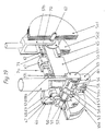
- the braking and measuring device according to the invention 18 and 19 or adjusting device 7a for the weight 5a works as follows: When the electromagnet 50 is not excited, the Brake disc 46 through the permanent magnet 49 via brake shoes 47 tightened and slowed down.
- the brake disc 46 is via an adapter sleeve 52 rigidly connected to a shaft 51.
- Permanent magnet and electromagnet are via a bearing sleeve 53, which is screwed to the arm 17e, rigidly with this connected.
- the shaft 51 is thus rigid with the arm 17e in this state connected.
- a pivoting of the arm 17d is basically via the bearings 54b possible.
- the part 17i and the bearing sleeve 53 is one Encoder disk 56 rigidly connected to the shaft 51.
- Bending beam 58 holds.
- the bending beam 58 is free of play between two held stops 59 held.
- the stops 59 are rigid in a measuring body 65 of the measuring device 6h. The latter is for clarification shown cut.
- the measuring body 65 is rigid with the part 17i and thus connected to part 17d. It is pivoted over its bearings 54 thus stopped.
- Strain gauges 60 are mounted on this, as the measurement result Moderate electrical voltage pulses from a corresponding control.
- strain gauges and bending beams other measuring elements such as piezo elements or the like. in itself known form replace the variant shown as an example.
- a preferred measurement and control routine enables this control of the counterweights at different speeds. So can For example, for voltage values between plus / minus 10 volts, the command for a quick adjustment can be triggered, whereby between plus / minus 5 volts normal adjustment speed is induced and in the range between plus / minus 2 volts after a voltage ramp a slowed down to desired setting value of the counterweight is specified. Likewise are 14 variants conceivable within the scope of the computer control, with waiting times between current measurement results and current displacement processes. Measurements are usually taken with the brakes applied. Brakes released allow an operator to change the position of the tripod.
- absolute position measurements of the or at least one Balance weight 5a is provided relative to its support arm 17e.
- Optical or magnetic bar code 70 is replaced by a magnetic or optical sensor element 71 scanned.
- the sensor element is direct or indirectly connected to the balance weight 5a, so that its position on Arm 17e is noticeable.
- Absolute position measurements have the advantage, according to a further design of the computer control 14 as a function of Load changes with the counterweight 5 targeted to a specific To be able to drive compensation positions. Basic settings or calibrations are therefore also possible.
- the controller can already the approximate when mounting an additional part on the load (load increase) Specify the weight of this component, after which the control is still without Carrying out a measurement at the measuring device 6a a positioning (Repositioning) the balance weight.
- a special one simple variant is based on that factor which is dependent on the Geometry of the tripod is determined.
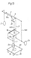
- Fig. 20 represents an alternative, which in turn with only a balance weight 5d needs.
- Swivel status can be adjusted by adjusting 5d - comparable to a scale unbraked condition the load 3 (for the horizontal swivel movement) can be compensated so that the tripod above the vertical pivot axis 18 in Rest is there.
- a dragonfly construction 19b or the like is measured. on one of the now horizontal bars (e.g. 2c).
- Either not about one here shown calculator or as mentioned above can be used to balance the System for pivoting in the vertical plane of the lower part of the arm 17d and the arm 40b3 can be displaced by means of spindle drives 11d and 11e, respectively that this leads to an approximation of the balance weight 5d or to a Distance from the vertical pivot axis 18 leads. That is one Balancing for the vertical swiveling movement achievable, so that at inclined arms 40a / b or 17d equilibrium prevails.
- a balance in the vertical pivoted position can be measured to control the actuators 11d, e.
Landscapes
- Engineering & Computer Science (AREA)
- General Engineering & Computer Science (AREA)
- Mechanical Engineering (AREA)
- Physics & Mathematics (AREA)
- General Physics & Mathematics (AREA)
- Optics & Photonics (AREA)
- Microscoopes, Condenser (AREA)
- Manipulator (AREA)
Claims (20)
- Support pour porter une charge (3), en particulier d'un microscope fonctionnel, comprenant un pied (1) avec au moins un bras de charge (2) pour la charge (3) et au moins un bras d'équilibrage (4) pour un poids d'équilibrage (5) et avec au moins un axe de rotation (18), autour duquel le bras de charge (2) et le bras d'équilibrage (4) sont montés pivotants, un frein (10) pour arrêter le mouvement du bras de charge (2) et du bras d'équilibrage autour de l'axe de rotation (18) étant prévu et le poids d'équilibrage (5) étant réalisé de manière déplaçable le long du bras d'équilibrage (4) et étant divisé en deux poids partiels (5a, 5b) et un dispositif de mesure (6) pour déterminer l'état d'équilibre et un dispositif de déplacement télécommandable (7a ; 7b) pour ajuster le poids d'équilibrage (5) étant prévus pour un équilibrage automatique des variations de poids sur le bras de charge (2) ou du bras de charge (2) par rapport au pied (1), caractérisé en ce qu'approximativement, l'un des poids partiels (5a) correspond au poids absolu de la charge (3) et l'autre poids partiel (5b) correspond au poids absolu du bras de charge (2) et du bras d'équilibrage (4) conjointement avec la charge (3) et le premier poids partiel (5a), le dispositif de mesure (6) est réalisé avec un capteur (19) pour mesurer, en fonction de la charge et indépendamment de la position, l'état d'équilibre du support lorsque le frein (10) est activé, et le dispositif de mesure (6) communiquant des premiers paramètres au dispositif de déplacement télécommandable (7a) pour l'ajustement du premier poids partiel (5a) et comprenant un ordinateur (14) qui calcule des deuxièmes paramètres à partir de ces premiers paramètres de déplacement et les communique au dispositif de déplacement télécommandable (7b) pour l'ajustement du deuxième poids partiel (5b) et de ce fait les deux poids partiels (5a, 5b) peuvent être ajustés automatiquement.
- Support selon la revendication 1, caractérisé en ce que les dispositifs de déplacement (7a,b) sont accouplés de préférence par le biais d'un accouplement (14), l'accouplement s'effectuant de manière électrique ou électronique et présentant éventuellement un logiciel qui comprend un facteur de multiplication, une formule pour calculer les paramètres de déplacement des poids d'équilibrage accouplés (5a, 5b).
- Support selon la revendication 1 ou 2, caractérisé en ce que le capteur (19) est réalisé en tant que capteur micromécanique ou microélectronique de pression, de flexion ou de couple, et est disposé dans la région de suspension de la charge (8), du pied (1), sur le bras de charge, d'équilibrage (2, 4) ou, dans le cas d'un axe de pivotement (9) pouvant être bloqué, pour au moins l'un des bras (2, 4) ou dans le cas de bras ou d'axes de pivotement connectés à des composants élargis.
- Support selon l'une quelconque des revendications précédentes, caractérisé en ce que le dispositif de déplacement (7), respectivement un entraínement (11) pour celui-ci, peut être actionné en fonction des valeurs de mesure du dispositif de mesure (6) avec diverses vitesses d'avance et en ce qu'il est connecté de préférence par le biais d'une broche d'entraínement (12) - éventuellement autobloquante - au moins indirectement au poids d'équilibrage (5a).
- Support selon l'une quelconque des revendications précédentes, caractérisé en ce qu'un dispositif de détermination de position absolue (70) est associé à au moins un poids d'équilibrage (5), pour l'établissement d'une position réelle du poids d'équilibrage (5) par rapport au bras d'équilibrage associé, celle-ci étant de préférence connectée à un ordinateur (14) qui détermine la position de départ du poids d'équilibrage (5) et commande l'entraínement (11) pour le positionnement du poids d'équilibrage (5).
- Support selon l'une quelconque des revendications précédentes, caractérisé en ce qu'un dispositif de détermination de position absolue (70) est associé à chaque poids d'équilibrage (5) et en ce qu'un dispositif de commande est prévu, lequel commande l'entraínement (11) au moins d'un poids d'équilibrage (5) en fonction de la position de l'autre poids d'équilibrage - éventuellement par le biais de tables ou de facteurs calculés - de telle sorte que celui-ci soit déplacé à une position déterminée, pouvant être détectée par le dispositif de détermination de position absolue (70), le dispositif de détermination de position absolue comprenant de préférence un capteur optique (71) et un code de marquage (7).
- Support comprenant au moins un guide parallèle (15) pour un bras de charge (2a) et au moins un deuxième guide parallèle vertical (16) pour un bras d'équilibrage (4a), les deux guides (15, 16) étant accouplés l'un à l'autre, selon l'une quelconque des revendications précédentes, caractérisé en ce que le dispositif de mesure (6) est disposé dans la région du guide parallèle vertical (15) et présente, sur une commande (14), à chaque fois un entraínement (11a,b) - de préférence électrique - pour déplacer au moins un poids d'équilibrage (5b,c) sur le premier et le deuxième guides parallèles (15, 16) ou sur deux bras différents de l'un des deux guides parallèles (15, 16).
- Support comprenant au moins un guide parallèle (15) pour un bras de charge (2a) et au moins un deuxième guide parallèle (16) pour le bras d'équilibrage (4a) et au moins un troisième guide parallèle (17) pour un transfert de mouvement entre le premier et le deuxième guides parallèles (15, 16), au moins un entraínement de réglage (11) pour le réglage de la géométrie du deuxième guide parallèle (16) étant prévu, selon l'une quelconque des revendications précédentes, caractérisé en ce qu'un dispositif de mesure (6) est associé à l'entraínement de réglage (11), - de préférence dans un axe de pivotement vertical (18) du troisième guide parallèle (17) et modifie, en fonction de variations du poids sur la charge (3) la géométrie du troisième guide parallèle (17) en vue d'un déplacement du centre de gravité du poids d'équilibrage (5) par rapport à l'axe de pivotement vertical (18).
- Support comprenant deux poids d'équilibrage (5) réglables, selon l'une quelconque des revendications précédentes, caractérisé en ce qu'un accouplement des deux poids d'équilibrage (5) s'effectue par le biais d'une commande électronique supportée par des formules (14) et d'un entraínement respectif (11), de préférence un dispositif de réglage (22) étant prévu en outre pour effectuer un ajustement de base manuel en fonction du poids de la charge (3), à la main ou au moyen de l'entraínement (11), et en ce qu'un ajustement fin peut être effectué au moyen du dispositif de mesure électronique (6), de la commande (14) et de l'entraínement électrique (11).
- Support selon l'une quelconque des revendications précédentes, caractérisé en ce qu'au lieu ou en plus du dispositif de mesure (6), un détecteur de valeur de mesure mécanique est connecté directement ou indirectement à l'un des bras (2, 4), se présente en particulier sous la forme d'un capteur de position, qui coopère simultanément, en tant que butée pour protéger contre une déformation mécanique trop importante du dispositif de mesure, à une butée conjuguée, et/ou qui est réalisé éventuellement en outre en tant que capteur de position pour un commutateur de fin de course électrique, qui est connecté à l'entraínement de réglage, de préférence un ressort éventuellement ajustable étant disposé entre le capteur de position et le commutateur, et/ou en ce que de préférence le commutateur commande, en tant qu'organe de commande, un entraínement électrique pour le réglage de préférence d'urgence ou de sécurité d'un poids d'équilibrage (5).
- Support selon l'une quelconque des revendications précédentes, caractérisé en ce qu'une commande d'entraínement éventuellement télécommandée, actionnable manuellement, et/ou un dispositif de réglage manuel d'urgence sans courant sont prévus en plus des dispositifs de réglages éventuels supportés par des valeurs de mesure pour les poids d'équilibrage.
- Support selon l'une quelconque des revendications précédentes, caractérisé en ce que la commande (14) de l'entraínement de déplacement (11) est accouplée au dispositif de freinage (10) et est éventuellement pourvue d'un circuit de retard temporel, de sorte qu'une mesure et/ou un déplacement ne s'effectue que lorsque le dispositif de freinage (10) est serré - éventuellement avec un retard temporel.
- Support selon l'une quelconque des revendications précédentes, caractérisé en ce que dans la région de la charge (3) ou de suspension de la charge (8) sont disposés d'autres dispositifs de déplacement automatiques pour la charge (3) ou les poids d'équilibrage (5) sur la charge (3), avec une direction d'action préférée perpendiculaire au plan dans lequel se trouvent les bras (2, 4).
- Support, en particulier pour des microscopes fonctionnels, selon l'une quelconque des revendications précédentes, caractérisé en ce que des pièces, en particulier des bras du support, sont fabriquées en matériaux composites renforcés par des fibres, par exemple en plastique renforcé par des fibres de verre, en matière plastique armée aux fibres de verre, en carbone ou en fibres de carbone, en fibres d'aramide ou de kevlar.
- Support selon l'une quelconque des revendications précédentes, caractérisé en ce que le pied (1) peut être réglé en hauteur et/ou basculé - éventuellement de manière télescopable - par rapport à la base (23), et/ou en ce qu'au moins l'une de plusieurs roues (25) de la base (23) peut être retirée par rapport à cette base - en particulier par télécommande - au-delà de la mesure d'une mise à niveau usuelle, où, de préférence dans le cas d'un pied (1) qui est monté rotatif par rapport à la base (23), celui-ci est supporté par un roulement à rouleaux croisés (24) par rapport à la base (23).
- Support avec des freins desserrables de manière électromagnétique dans les articulations, selon l'une quelconque des revendications précédentes, caractérisé en ce qu'un circuit est associé à l'électroaimant (50), lequel circuit diminue la tension au niveau de la bobine de l'électroaimant (50) par degrés ou suivant une rampe lorsque l'électroaimant (50) n'est plus parcouru par un courant, et/ou en ce que l'on prévoit comme élément de serrage pour l'état de freinage des freins (10), un aimant permanent (49) dont le magnétisme peut être interrompu par l'électroaimant (50) pour l'état desserré.
- Support selon l'une quelconque des revendications précédentes, caractérisé en ce que le bras de charge (2) est réalisé, depuis l'axe de pivotement horizontal (9) jusqu'à la charge (3) avec la même longueur, de préférence avec la même forme que le bras de pivotement vertical (40a) qui le porte, depuis l'axe de pivotement vertical (18) jusqu'à l'axe de pivotement horizontal (9), les deux se trouvant éventuellement dans des plans parallèles et étant connectés l'un à l'autre au niveau de l'axe de pivotement horizontal (9).
- Procédé pour l'équilibrage d'un support, en particulier pour un microscope fonctionnel comprenant un pied (1), avec un axe de pivotement vertical (18), autour duquel le support pivote depuis un plan vertical, avec un axe de pivotement horizontal (9), autour duquel le support pivote depuis un plan horizontal et avec un pied de pivotement (40) connectant l'axe de pivotement vertical (18) et l'axe de pivotement horizontal (9) et avec au moins un bras de charge (2) pour la charge (3) et au moins un bras d'équilibrage (4) pour un poids d'équilibrage (5) télécommandable électriquement, qui peut être déplacé le long du bras d'équilibrage (4) au moins d'un dispositif de déplacement (7), pour équilibrer les variations de poids ou de position sur le ou du bras de charge (2) par rapport au pied (1), un poids d'équilibrage en deux parties (Sa, 5b) étant prévu et le poids ou la variation du poids de la charge (3) étant mesuré(e) par un dispositif de mesure (6), l'un des poids d'équilibrage (5a) étant ensuite déplacé sur son bras d'équilibrage à partir de la valeur de mesure, afin de compenser automatiquement la variation de poids de la charge (3), caractérisé en ce que la mesure s'effectue indépendamment de la position de la charge (3), où, après la détection de la première valeur de mesure, un deuxième paramètre de déplacement est engendré au moyen de formules ou de tables pour le deuxième poids d'équilibrage (5b), ce poids d'équilibrage étant ensuite déplacé dans une position dans laquelle il est en mesure d'équilibrer le poids de la charge (3) et du bras de charge (2) avec le bras d'équilibrage ou les couples de flexion se produisant ou les couples de rotation en résultant lors d'un pivotement autour de l'axe de pivotement vertical (18), ou est en mesure d'effectuer l'équilibrage du support sur le pied (1), la pression dans ou sur des composants sollicités en traction ou en pression du support étant mesurée indépendamment de leur position respective en outre en variante au moyen d'un dispositif de mesure (6b,c,e), et/ou en ce qu'un moment de flexion est mesuré au moyen du dispositif de mesure (6a,f) sur ou entre deux composants du support indépendamment de leur position, et/ou un couple de rotation est mesuré au moyen d'un dispositif de mesure (6d) sur ou entre deux composants du support, en particulier autour d'un axe de pivotement d'un bras (2, 4) fixé pendant la mesure, indépendamment de la position angulaire de ce bras (2, 4).
- Procédé selon la revendication 18, caractérisé en ce que la valeur de mesure du dispositif de mesure (6) est convertie au moyen d'un convertisseur de valeurs de mesure, d'une commande ou d'un ordinateur (14), en au moins une valeur de commande pour au moins un entraínement électrique (11) et est acheminée à cet entraínement (11), l'entraínement (11) déplaçant le poids d'équilibrage (5) - de préférence en fonction de la valeur de mesure - dans au moins deux directions et suivant deux vitesses différentes, et le fixant éventuellement aussi dans la nouvelle position, par exemple au moyen de freins.
- Procédé de réglage de deux poids d'équilibrage indépendant l'un de l'autre (5a,b), l'un des poids d'équilibrage (5b) servant à l'équilibrage d'un poids statique modifié de la charge (3) sur son bras de charge horizontal ou son bras d'équilibrage, et l'autre poids d'équilibrage (5a) servant à l'équilibrage du poids du bras de charge horizontal et de la charge ainsi que du premier poids d'équilibrage pendant le pivotement des composants verticaux d'un support, la variation statique du poids de la charge (3) étant détectée par un dispositif de mesure (6) et le premier poids d'équilibrage (5b) étant déplacé automatiquement, caractérisé en ce que cette valeur de mesure est introduite dans un calcul, avec lequel la position d'équilibrage nécessaire de l'autre poids d'équilibrage (5a) est calculée, après quoi l'autre poids d'équilibrage (5a) est déplacé dans cette position d'équilibrage au moyen de l'entraínement électrique.
Applications Claiming Priority (4)
| Application Number | Priority Date | Filing Date | Title |
|---|---|---|---|
| CH2976/95 | 1995-10-12 | ||
| CH297695 | 1995-10-12 | ||
| CH297695 | 1995-10-12 | ||
| PCT/EP1996/004454 WO1997013997A1 (fr) | 1995-10-12 | 1996-10-12 | Support |
Publications (3)
| Publication Number | Publication Date |
|---|---|
| EP0855002A1 EP0855002A1 (fr) | 1998-07-29 |
| EP0855002B1 true EP0855002B1 (fr) | 2003-06-25 |
| EP0855002B2 EP0855002B2 (fr) | 2011-12-21 |
Family
ID=4245876
Family Applications (1)
| Application Number | Title | Priority Date | Filing Date |
|---|---|---|---|
| EP96934667A Expired - Lifetime EP0855002B2 (fr) | 1995-10-12 | 1996-10-12 | Support |
Country Status (5)
| Country | Link |
|---|---|
| US (1) | US6129319A (fr) |
| EP (1) | EP0855002B2 (fr) |
| JP (1) | JP4041536B2 (fr) |
| DE (2) | DE29624639U1 (fr) |
| WO (1) | WO1997013997A1 (fr) |
Cited By (3)
| Publication number | Priority date | Publication date | Assignee | Title |
|---|---|---|---|---|
| DE102007019363A1 (de) * | 2007-04-23 | 2008-11-06 | Jürgen Michael Knapp | Operations-Assistenz-System |
| DE10300620B4 (de) * | 2002-05-18 | 2017-04-13 | Carl Zeiss Meditec Ag | Trägervorrichtung für ein medizinisch-optisches Gerät |
| EP4458278A3 (fr) * | 2015-08-12 | 2025-01-22 | Brainlab Robotics GmbH | Bras de support médical avec moyens d'affichage annulaires à del |
Families Citing this family (59)
| Publication number | Priority date | Publication date | Assignee | Title |
|---|---|---|---|---|
| DE19751781C2 (de) * | 1996-11-22 | 2002-02-14 | Leica Mikroskopie Systeme Ag H | Mikroskop mit Positionsüberwachung |
| WO1998052484A1 (fr) | 1997-05-20 | 1998-11-26 | Leica Mikroskopie Systeme Ag | Support, notamment pour microscope d'operation |
| WO1998053244A1 (fr) * | 1997-05-20 | 1998-11-26 | Leica Mikroskopie Systeme Ag | Statif pour microscope, en particulier pour microscope d'operations |
| FR2775245A1 (fr) * | 1998-02-25 | 1999-08-27 | Vernay Etudes Conception | Dispositif et procede de correction de l'assiette d'un sous-ensemble mobile par rapport a un chassis de vehicule "terrestre" |
| DE19809022A1 (de) * | 1998-03-04 | 1999-09-09 | Krieter | Halterung für ein Operationsmikroskop |
| DE10042272B4 (de) | 2000-08-29 | 2012-10-31 | Leica Instruments (Singapore) Pte. Ltd. | Stativanordnung |
| DE50111444D1 (de) | 2000-09-28 | 2006-12-28 | Leica Microsystems Schweiz Ag | Stativ |
| DE20114343U1 (de) | 2000-09-30 | 2001-11-29 | Carl Zeiss, 89518 Heidenheim | Stativ |
| DE20019106U1 (de) * | 2000-11-12 | 2001-02-22 | Leica Microsystems Ag, Heerbrugg | Stativ mit Parallelogrammträger und Balanciermechanismus |
| DE20019105U1 (de) | 2000-11-12 | 2001-05-23 | Leica Microsystems Ag, Heerbrugg | Stativ |
| DE20019107U1 (de) | 2000-11-12 | 2001-01-25 | Leica Microsystems Ag, Heerbrugg | Stativ |
| DE20019109U1 (de) | 2000-11-12 | 2001-02-22 | Leica Microsystems Ag, Heerbrugg | Stativ, insbesondere für Operationsmikroskope |
| DE10123166A1 (de) * | 2001-03-31 | 2002-10-10 | Leica Microsystems | Stativ. insbesondere für ein Operationsmikroskop |
| JP4754738B2 (ja) * | 2001-08-30 | 2011-08-24 | オリンパス株式会社 | 医療用保持装置及び医療装置 |
| EP1295568A1 (fr) | 2001-09-20 | 2003-03-26 | Carl Zeiss | Instrument avec un drap |
| DE10155719A1 (de) | 2001-11-13 | 2003-05-22 | Leica Microsystems Schweiz Ag | Operations-Mikroskop |
| US6539333B1 (en) * | 2002-01-04 | 2003-03-25 | Leica Microsystems Ag | Stand having an automatic balancing device |
| JP4532188B2 (ja) * | 2003-06-30 | 2010-08-25 | カール−ツアイス−スチフツング | 負荷回転モーメントを補償する手段を有する、殊に医療用光学器具のための保持装置 |
| US7170250B2 (en) * | 2003-06-30 | 2007-01-30 | Carl Zeiss Surgical Gmbh | Holding arrangement having a device for actively damping vibration |
| DE102004008381B4 (de) * | 2003-06-30 | 2014-09-25 | Carl Zeiss Meditec Ag | Haltevorrichtung, insbesondere für ein medizinisch-optisches Instrument, mit Mitteln zum Ausgleich eines Last-Drehmoments sowie ein Verfahren zum Einstellen eines Gleichgewichtszustandes in einer Haltevorrichtung |
| US7594188B2 (en) * | 2003-08-21 | 2009-09-22 | Carl Zeiss Ag | Operating menu for a surgical microscope |
| DE102004005094A1 (de) | 2004-01-27 | 2005-08-18 | Carl Zeiss | Gerätehaltevorrichtung |
| DE102004004678B4 (de) * | 2004-01-29 | 2005-12-29 | Otto Bock Healthcare Gmbh | Drehmomentsensor |
| US7172105B2 (en) * | 2004-04-01 | 2007-02-06 | Amaesing Tools Mfg. Inc. | Apparatus for positioning pipe and tubing |
| US7543791B2 (en) * | 2005-10-19 | 2009-06-09 | Brown University | Tunable inverse pendulum vibration isolation system |
| DE102007030892A1 (de) * | 2007-05-09 | 2008-11-20 | Schaeffler Kg | Verfahren zum Messen von Beugemomenten an einem Gelenk und Messanordnung zur Durchführung des Verfahrens |
| US7677129B2 (en) * | 2007-09-28 | 2010-03-16 | Intuitive Surgical, Inc. | Multiaxis counterbalance and positioning system using a spatial linkage |
| JP2010149195A (ja) * | 2008-12-24 | 2010-07-08 | Iwao Yuasa | 工具等重量軽減、作業支援装置 |
| US9366378B2 (en) * | 2009-02-11 | 2016-06-14 | Siemens Medical Solutions Usa, Inc. | Support arm for ultrasound scanning |
| DE102010051633A1 (de) * | 2010-11-17 | 2012-05-24 | Ondal Medical Systems Gmbh | Tragesystem mit Bedienungshilfe |
| DE202011110285U1 (de) * | 2011-04-01 | 2013-10-31 | Aevum Mechatronik Gmbh | Einrichtung zur Erzeugung von Drehbewegungen, Vorrichtung sowie medizinische Leuchte |
| US8602612B2 (en) | 2011-05-12 | 2013-12-10 | Peter Stathis | Electrically conductive ball joints and lighting fixtures using the joints |
| DE102011114525B4 (de) * | 2011-09-29 | 2015-10-15 | Carl Zeiss Meditec Ag | Operationsmikroskop mit Wärme erzeugender Komponente und mit Kühlvorrichtung |
| DE102011056086A1 (de) * | 2011-12-06 | 2013-06-06 | Leica Microsystems (Schweiz) Ag | Stativ zum Halten von mindestens einem medizinischen Gerät, insbesondere einem Mikroskop |
| DE102012100179B4 (de) * | 2012-01-11 | 2013-07-18 | Leica Microsystems (Schweiz) Ag | Stativ zum Halten von mindestens einem medizinischen Gerät, insbesondere einem Mikroskop, sowie Anordnung aus einem solchen Stativ und mindestens einem daran befestigten medizinischen Gerät |
| DE102012202222B3 (de) * | 2012-02-14 | 2013-06-06 | Leica Microsystems (Schweiz) Ag | Verstellbares Stativ |
| USD689644S1 (en) | 2012-05-11 | 2013-09-10 | Peter Stathis | Lighting fixture |
| USD689645S1 (en) | 2012-05-11 | 2013-09-10 | Peter Stathis | Lighting fixture |
| JP5961102B2 (ja) * | 2012-11-30 | 2016-08-02 | 三鷹光器株式会社 | 医療用バランシングスタンドの自動バランス調整構造 |
| JP5977659B2 (ja) * | 2012-12-06 | 2016-08-24 | 三鷹光器株式会社 | 医療用バランシングスタンドの自動バランス調整構造 |
| JP5953215B2 (ja) * | 2012-12-07 | 2016-07-20 | 三鷹光器株式会社 | 医療用バランシングスタンドの自動バランス調整構造 |
| DE102013201783B4 (de) * | 2013-02-04 | 2019-03-07 | Leica Microsystems (Schweiz) Ag | Lageausgleichsvorrichtung für Stative für medizinische Geräte |
| DE102013005999A1 (de) * | 2013-04-09 | 2014-10-09 | Carl Zeiss Microscopy Gmbh | Schwenkarmstativ für Digitalmikroskope |
| DE102014114479B3 (de) * | 2014-10-06 | 2016-02-25 | Leica Microsystems (Schweiz) Ag | Digitales mikroskop mit klickstopp |
| DE102014114478B3 (de) * | 2014-10-06 | 2016-02-25 | Leica Microsystems (Schweiz) Ag | Digitales Mikroskop mit federgelagerter schwenkbarer Einheit |
| DE102014114477B3 (de) * | 2014-10-06 | 2016-02-25 | Leica Microsystems (Schweiz) Ag | Digitales Mikroskop mit einem Radialkolbenbremssystem |
| US9945715B2 (en) * | 2015-09-30 | 2018-04-17 | The Boeing Company | Weight loader for moving at least two loads |
| JP6769600B2 (ja) * | 2016-07-14 | 2020-10-14 | 三鷹光器株式会社 | 手術顕微鏡装置 |
| CN108071922A (zh) * | 2016-11-11 | 2018-05-25 | 四川炜麒科技股份有限公司 | 一种流速监测仪用挂架 |
| US10767807B2 (en) | 2017-02-15 | 2020-09-08 | II Thomas Kulesia | Appliance stand |
| EP3518014B1 (fr) * | 2018-01-30 | 2020-11-18 | Leica Instruments (Singapore) Pte. Ltd. | Dispositif d'équilibrage et procédé d'équilibrage d'un microscope |
| DE102019208287B4 (de) * | 2019-06-06 | 2023-04-20 | Carl Zeiss Meditec Ag | Verfahren zum Betreiben eines Operationsmikroskopiesystems sowie Operationsmikroskopiesystem |
| CN110805817B (zh) * | 2019-11-13 | 2021-01-26 | 电子科技大学 | 基于粗精分离原理的下置悬挂式三自由度手机拍摄稳定器 |
| US20210236228A1 (en) * | 2020-01-31 | 2021-08-05 | Globus Medical, Inc. | Patient stabilization system |
| DE102020211130A1 (de) | 2020-09-03 | 2022-03-03 | Carl Zeiss Meditec Ag | Verfahren und Vorrichtung zur Balancierung eines Mikroskopiesystems |
| EP4362872B1 (fr) * | 2021-06-30 | 2026-04-29 | AMO Development, LLC | Mécanisme de contrepoids de système laser ophtalmique utilisant une bascule à fléau variable pour fournir une charge nette variable |
| US12516769B1 (en) * | 2023-04-20 | 2026-01-06 | Clifford B. Breed | Mobile overhead monitor bracket stand |
| DE102023119417A1 (de) * | 2023-07-21 | 2025-01-23 | HAW Hochschule für Angewandte Wissenschaften Hamburg, Körperschaft des öffentlichen Rechts | Haltevorrichtung für eine Komponente, System umfassend eine Haltevorrichtung und Verfahren zum Betreiben eines Systems |
| PL74289Y1 (pl) * | 2023-12-15 | 2026-03-09 | Tech4Stars Spolka Z Ograniczona Odpowiedzialnoscia | Statyw |
Family Cites Families (12)
| Publication number | Priority date | Publication date | Assignee | Title |
|---|---|---|---|---|
| CH548568A (de) * | 1972-08-18 | 1974-04-30 | Contraves Ag | Tragvorrichtung mit einem optischen beobachtungsgeraet. |
| US3891301A (en) * | 1972-08-18 | 1975-06-24 | Contraves Ag | Adjustable support or stand for an optical observation instrument |
| DE8400384U1 (de) * | 1983-03-01 | 1984-04-05 | Jenoptik Jena Gmbh, Ddr 6900 Jena | Vorrichtung zur Bewegung und Arretierung von Bodenstativen |
| DE9013260U1 (de) * | 1990-09-19 | 1990-11-22 | Fa. Carl Zeiss, 7920 Heidenheim | Tragvorrichtung mit Gewichtsausgleich für ein Operationsmikroskop |
| JP3040806B2 (ja) † | 1990-10-03 | 2000-05-15 | 株式会社トプコン | 顕微鏡装置 |
| JPH066136B2 (ja) * | 1991-12-25 | 1994-01-26 | 佐原 今朝徳 | 医療用光学機器のスタンド装置 |
| JP2825721B2 (ja) * | 1992-12-28 | 1998-11-18 | 三鷹光器株式会社 | 医療用光学機器のスタンド装置 |
| JPH0773587B2 (ja) * | 1993-03-18 | 1995-08-09 | 三鷹光器株式会社 | 医療用スタンド装置の2軸バランス調整構造 |
| US5812301A (en) * | 1993-06-15 | 1998-09-22 | Mitaka Kohki Co., Ltd. | Stand for optical devices |
| DE4320443C2 (de) * | 1993-06-21 | 2001-08-02 | Zeiss Carl | Ausbalancierbares Stativ |
| DE4334069A1 (de) * | 1993-06-21 | 1995-04-13 | Zeiss Carl Fa | Ausbalancierbares Stativ |
| US5713545A (en) * | 1995-12-13 | 1998-02-03 | Mitaka Kohki Co. Ltd. | Stand apparatus for medical optical equipments |
-
1996
- 1996-10-12 WO PCT/EP1996/004454 patent/WO1997013997A1/fr not_active Ceased
- 1996-10-12 JP JP51472797A patent/JP4041536B2/ja not_active Expired - Fee Related
- 1996-10-12 EP EP96934667A patent/EP0855002B2/fr not_active Expired - Lifetime
- 1996-10-12 DE DE29624639U patent/DE29624639U1/de not_active Expired - Lifetime
- 1996-10-12 DE DE59610558T patent/DE59610558D1/de not_active Expired - Lifetime
- 1996-10-12 US US09/043,404 patent/US6129319A/en not_active Expired - Lifetime
Cited By (4)
| Publication number | Priority date | Publication date | Assignee | Title |
|---|---|---|---|---|
| DE10300620B4 (de) * | 2002-05-18 | 2017-04-13 | Carl Zeiss Meditec Ag | Trägervorrichtung für ein medizinisch-optisches Gerät |
| DE102007019363A1 (de) * | 2007-04-23 | 2008-11-06 | Jürgen Michael Knapp | Operations-Assistenz-System |
| DE102007019363B4 (de) * | 2007-04-23 | 2009-06-25 | Jürgen Michael Knapp | Operations-Assistenz-System |
| EP4458278A3 (fr) * | 2015-08-12 | 2025-01-22 | Brainlab Robotics GmbH | Bras de support médical avec moyens d'affichage annulaires à del |
Also Published As
| Publication number | Publication date |
|---|---|
| US6129319A (en) | 2000-10-10 |
| JP2001509861A (ja) | 2001-07-24 |
| JP4041536B2 (ja) | 2008-01-30 |
| WO1997013997A1 (fr) | 1997-04-17 |
| EP0855002A1 (fr) | 1998-07-29 |
| EP0855002B2 (fr) | 2011-12-21 |
| DE59610558D1 (de) | 2003-07-31 |
| DE29624639U1 (de) | 2006-06-08 |
Similar Documents
| Publication | Publication Date | Title |
|---|---|---|
| EP0855002B1 (fr) | Support | |
| EP0433426B1 (fr) | Statif equipe de dispositifs accessoires, pour supporter un appareil librement orientable | |
| EP1207334A1 (fr) | Support | |
| EP0023004B1 (fr) | Dispositif additionnel prévu sur le support d'un appareil d'observation optique | |
| DE102008011638B4 (de) | Balanciervorrichtung für Operations-Mikroskop | |
| DE102008011639A1 (de) | Stativ, insbesondere für ein Operations-Mikroskop | |
| DE102007059520A1 (de) | Medizinischer Tisch zum Lagern von Patienten und zugehöriges Verfahren | |
| EP1273954A2 (fr) | Support | |
| EP1336884B1 (fr) | Système de microscope microchirurgical | |
| EP1336885B1 (fr) | Système microscopique microchirurgical | |
| DE102008011640A1 (de) | Balanciervorrichtung für Operations-Mikroskop | |
| WO2014023779A1 (fr) | Dispositif de guidage stabilisé d'un dispositif de prise de vues | |
| DE102014223435A1 (de) | Trainingsvorrichtung mit 3D-Positionserfassung und deren Betriebsverfahren | |
| DE102011119814A1 (de) | Stativ | |
| EP0864063B1 (fr) | Pied pour un microscope, notamment pour un microscope d'intervention chirurgicale | |
| EP1251380A2 (fr) | Statif pour un microscope d'opération | |
| DE102007000253A1 (de) | Transportabler teleskopierbarer Maschinenständer für eine Elektrohandwerkzeugmaschine | |
| DE10145197B4 (de) | Entkoppelter Gewichtsausgleich für eine Kamera-Balance-Vorrichtung | |
| DE10163354A1 (de) | Vorrichtung zum Halten einer optischen Betrachtungseinrichtung | |
| EP1101139B1 (fr) | Statif pour microscope pour operations pour deplacement x-y | |
| EP1205703B1 (fr) | Support,en particulier pour microscope chirurgical | |
| DE10314156B9 (de) | Schwenkhalterungsanordnung und Verfahren zum Steuern einer solchen | |
| DE102008033357A1 (de) | Aufhängungssystem, insbesondere für Bildaufzeichnungsgeräte | |
| WO2005004465A1 (fr) | Systeme a tete pivotante, en particulier pour camera a film et camera video | |
| DE2320266C3 (de) | Verstellbares Stativ für ein optisches Beobachtungsgerät, insbesondere ein Binokularmikroskop |
Legal Events
| Date | Code | Title | Description |
|---|---|---|---|
| PUAI | Public reference made under article 153(3) epc to a published international application that has entered the european phase |
Free format text: ORIGINAL CODE: 0009012 |
|
| 17P | Request for examination filed |
Effective date: 19980307 |
|
| AK | Designated contracting states |
Kind code of ref document: A1 Designated state(s): CH DE FR GB LI |
|
| 17Q | First examination report despatched |
Effective date: 19991028 |
|
| RBV | Designated contracting states (corrected) |
Designated state(s): CH DE FR GB LI |
|
| GRAH | Despatch of communication of intention to grant a patent |
Free format text: ORIGINAL CODE: EPIDOS IGRA |
|
| GRAH | Despatch of communication of intention to grant a patent |
Free format text: ORIGINAL CODE: EPIDOS IGRA |
|
| GRAH | Despatch of communication of intention to grant a patent |
Free format text: ORIGINAL CODE: EPIDOS IGRA |
|
| GRAA | (expected) grant |
Free format text: ORIGINAL CODE: 0009210 |
|
| AK | Designated contracting states |
Designated state(s): CH DE FR GB LI |
|
| REG | Reference to a national code |
Ref country code: GB Ref legal event code: FG4D Free format text: NOT ENGLISH |
|
| REG | Reference to a national code |
Ref country code: CH Ref legal event code: EP |
|
| REF | Corresponds to: |
Ref document number: 59610558 Country of ref document: DE Date of ref document: 20030731 Kind code of ref document: P |
|
| GBT | Gb: translation of ep patent filed (gb section 77(6)(a)/1977) | ||
| ET | Fr: translation filed | ||
| PLBI | Opposition filed |
Free format text: ORIGINAL CODE: 0009260 |
|
| PLAX | Notice of opposition and request to file observation + time limit sent |
Free format text: ORIGINAL CODE: EPIDOSNOBS2 |
|
| 26 | Opposition filed |
Opponent name: CARL ZEISS Effective date: 20040325 |
|
| PLAB | Opposition data, opponent's data or that of the opponent's representative modified |
Free format text: ORIGINAL CODE: 0009299OPPO |
|
| PLAX | Notice of opposition and request to file observation + time limit sent |
Free format text: ORIGINAL CODE: EPIDOSNOBS2 |
|
| PLAX | Notice of opposition and request to file observation + time limit sent |
Free format text: ORIGINAL CODE: EPIDOSNOBS2 |
|
| R26 | Opposition filed (corrected) |
Opponent name: CARL ZEISS AG Effective date: 20040325 |
|
| RAP2 | Party data changed (patent owner data changed or rights of a patent transferred) |
Owner name: LEICA MICROSYSTEMS (SCHWEIZ) AG |
|
| PLAX | Notice of opposition and request to file observation + time limit sent |
Free format text: ORIGINAL CODE: EPIDOSNOBS2 |
|
| PLBB | Reply of patent proprietor to notice(s) of opposition received |
Free format text: ORIGINAL CODE: EPIDOSNOBS3 |
|
| RDAF | Communication despatched that patent is revoked |
Free format text: ORIGINAL CODE: EPIDOSNREV1 |
|
| APBP | Date of receipt of notice of appeal recorded |
Free format text: ORIGINAL CODE: EPIDOSNNOA2O |
|
| APAH | Appeal reference modified |
Free format text: ORIGINAL CODE: EPIDOSCREFNO |
|
| APBQ | Date of receipt of statement of grounds of appeal recorded |
Free format text: ORIGINAL CODE: EPIDOSNNOA3O |
|
| APAH | Appeal reference modified |
Free format text: ORIGINAL CODE: EPIDOSCREFNO |
|
| APBU | Appeal procedure closed |
Free format text: ORIGINAL CODE: EPIDOSNNOA9O |
|
| PGFP | Annual fee paid to national office [announced via postgrant information from national office to epo] |
Ref country code: CH Payment date: 20081015 Year of fee payment: 13 |
|
| PGFP | Annual fee paid to national office [announced via postgrant information from national office to epo] |
Ref country code: FR Payment date: 20081014 Year of fee payment: 13 |
|
| PGFP | Annual fee paid to national office [announced via postgrant information from national office to epo] |
Ref country code: GB Payment date: 20081021 Year of fee payment: 13 |
|
| PLAY | Examination report in opposition despatched + time limit |
Free format text: ORIGINAL CODE: EPIDOSNORE2 |
|
| PLAH | Information related to despatch of examination report in opposition + time limit modified |
Free format text: ORIGINAL CODE: EPIDOSCORE2 |
|
| PLBC | Reply to examination report in opposition received |
Free format text: ORIGINAL CODE: EPIDOSNORE3 |
|
| REG | Reference to a national code |
Ref country code: CH Ref legal event code: PL |
|
| REG | Reference to a national code |
Ref country code: FR Ref legal event code: ST Effective date: 20100630 |
|
| PG25 | Lapsed in a contracting state [announced via postgrant information from national office to epo] |
Ref country code: FR Free format text: LAPSE BECAUSE OF NON-PAYMENT OF DUE FEES Effective date: 20091102 |
|
| PG25 | Lapsed in a contracting state [announced via postgrant information from national office to epo] |
Ref country code: LI Free format text: LAPSE BECAUSE OF NON-PAYMENT OF DUE FEES Effective date: 20091031 Ref country code: CH Free format text: LAPSE BECAUSE OF NON-PAYMENT OF DUE FEES Effective date: 20091031 |
|
| PG25 | Lapsed in a contracting state [announced via postgrant information from national office to epo] |
Ref country code: GB Free format text: LAPSE BECAUSE OF NON-PAYMENT OF DUE FEES Effective date: 20091012 |
|
| PLAB | Opposition data, opponent's data or that of the opponent's representative modified |
Free format text: ORIGINAL CODE: 0009299OPPO |
|
| R26 | Opposition filed (corrected) |
Opponent name: CARL ZEISS AG Effective date: 20040325 |
|
| PUAH | Patent maintained in amended form |
Free format text: ORIGINAL CODE: 0009272 |
|
| STAA | Information on the status of an ep patent application or granted ep patent |
Free format text: STATUS: PATENT MAINTAINED AS AMENDED |
|
| 27A | Patent maintained in amended form |
Effective date: 20111221 |
|
| AK | Designated contracting states |
Kind code of ref document: B2 Designated state(s): CH DE FR GB LI |
|
| REG | Reference to a national code |
Ref country code: DE Ref legal event code: R102 Ref document number: 59610558 Country of ref document: DE |
|
| REG | Reference to a national code |
Ref country code: DE Ref legal event code: R102 Ref document number: 59610558 Country of ref document: DE Effective date: 20111221 |
|
| PGFP | Annual fee paid to national office [announced via postgrant information from national office to epo] |
Ref country code: DE Payment date: 20141022 Year of fee payment: 19 |
|
| REG | Reference to a national code |
Ref country code: DE Ref legal event code: R119 Ref document number: 59610558 Country of ref document: DE |
|
| PG25 | Lapsed in a contracting state [announced via postgrant information from national office to epo] |
Ref country code: DE Free format text: LAPSE BECAUSE OF NON-PAYMENT OF DUE FEES Effective date: 20160503 |