EP1207334A1 - Support - Google Patents
Support Download PDFInfo
- Publication number
- EP1207334A1 EP1207334A1 EP01125606A EP01125606A EP1207334A1 EP 1207334 A1 EP1207334 A1 EP 1207334A1 EP 01125606 A EP01125606 A EP 01125606A EP 01125606 A EP01125606 A EP 01125606A EP 1207334 A1 EP1207334 A1 EP 1207334A1
- Authority
- EP
- European Patent Office
- Prior art keywords
- arm
- cable
- support arm
- tripod
- weight
- Prior art date
- Legal status (The legal status is an assumption and is not a legal conclusion. Google has not performed a legal analysis and makes no representation as to the accuracy of the status listed.)
- Granted
Links
- 230000008859 change Effects 0.000 claims description 8
- 230000005540 biological transmission Effects 0.000 claims description 5
- 238000012546 transfer Methods 0.000 claims description 5
- 238000010276 construction Methods 0.000 description 17
- 230000000694 effects Effects 0.000 description 8
- 238000013519 translation Methods 0.000 description 7
- 230000014616 translation Effects 0.000 description 7
- 230000005484 gravity Effects 0.000 description 5
- 238000011161 development Methods 0.000 description 4
- 230000018109 developmental process Effects 0.000 description 4
- 230000033001 locomotion Effects 0.000 description 4
- 238000012549 training Methods 0.000 description 4
- 239000003795 chemical substances by application Substances 0.000 description 3
- 239000000969 carrier Substances 0.000 description 2
- 230000008878 coupling Effects 0.000 description 2
- 238000010168 coupling process Methods 0.000 description 2
- 238000005859 coupling reaction Methods 0.000 description 2
- 238000006073 displacement reaction Methods 0.000 description 2
- 230000006872 improvement Effects 0.000 description 2
- 230000009467 reduction Effects 0.000 description 2
- 230000008901 benefit Effects 0.000 description 1
- 230000015572 biosynthetic process Effects 0.000 description 1
- 230000000903 blocking effect Effects 0.000 description 1
- 230000001447 compensatory effect Effects 0.000 description 1
- 230000006835 compression Effects 0.000 description 1
- 238000007906 compression Methods 0.000 description 1
- 238000012937 correction Methods 0.000 description 1
- 238000005516 engineering process Methods 0.000 description 1
- 238000007667 floating Methods 0.000 description 1
- 238000001423 gas--liquid extraction Methods 0.000 description 1
- 238000005286 illumination Methods 0.000 description 1
- 238000004519 manufacturing process Methods 0.000 description 1
- 238000005259 measurement Methods 0.000 description 1
- 230000007246 mechanism Effects 0.000 description 1
- 238000000034 method Methods 0.000 description 1
- 230000008569 process Effects 0.000 description 1
- 238000004804 winding Methods 0.000 description 1
Images




Classifications
-
- F—MECHANICAL ENGINEERING; LIGHTING; HEATING; WEAPONS; BLASTING
- F16—ENGINEERING ELEMENTS AND UNITS; GENERAL MEASURES FOR PRODUCING AND MAINTAINING EFFECTIVE FUNCTIONING OF MACHINES OR INSTALLATIONS; THERMAL INSULATION IN GENERAL
- F16M—FRAMES, CASINGS OR BEDS OF ENGINES, MACHINES OR APPARATUS, NOT SPECIFIC TO ENGINES, MACHINES OR APPARATUS PROVIDED FOR ELSEWHERE; STANDS; SUPPORTS
- F16M11/00—Stands or trestles as supports for apparatus or articles placed thereon ; Stands for scientific apparatus such as gravitational force meters
- F16M11/42—Stands or trestles as supports for apparatus or articles placed thereon ; Stands for scientific apparatus such as gravitational force meters with arrangement for propelling the support stands on wheels
-
- A—HUMAN NECESSITIES
- A61—MEDICAL OR VETERINARY SCIENCE; HYGIENE
- A61B—DIAGNOSIS; SURGERY; IDENTIFICATION
- A61B90/00—Instruments, implements or accessories specially adapted for surgery or diagnosis and not covered by any of the groups A61B1/00 - A61B50/00, e.g. for luxation treatment or for protecting wound edges
- A61B90/20—Surgical microscopes characterised by non-optical aspects
- A61B90/25—Supports therefor
-
- F—MECHANICAL ENGINEERING; LIGHTING; HEATING; WEAPONS; BLASTING
- F16—ENGINEERING ELEMENTS AND UNITS; GENERAL MEASURES FOR PRODUCING AND MAINTAINING EFFECTIVE FUNCTIONING OF MACHINES OR INSTALLATIONS; THERMAL INSULATION IN GENERAL
- F16M—FRAMES, CASINGS OR BEDS OF ENGINES, MACHINES OR APPARATUS, NOT SPECIFIC TO ENGINES, MACHINES OR APPARATUS PROVIDED FOR ELSEWHERE; STANDS; SUPPORTS
- F16M11/00—Stands or trestles as supports for apparatus or articles placed thereon ; Stands for scientific apparatus such as gravitational force meters
- F16M11/02—Heads
- F16M11/04—Means for attachment of apparatus; Means allowing adjustment of the apparatus relatively to the stand
- F16M11/06—Means for attachment of apparatus; Means allowing adjustment of the apparatus relatively to the stand allowing pivoting
- F16M11/08—Means for attachment of apparatus; Means allowing adjustment of the apparatus relatively to the stand allowing pivoting around a vertical axis, e.g. panoramic heads
-
- F—MECHANICAL ENGINEERING; LIGHTING; HEATING; WEAPONS; BLASTING
- F16—ENGINEERING ELEMENTS AND UNITS; GENERAL MEASURES FOR PRODUCING AND MAINTAINING EFFECTIVE FUNCTIONING OF MACHINES OR INSTALLATIONS; THERMAL INSULATION IN GENERAL
- F16M—FRAMES, CASINGS OR BEDS OF ENGINES, MACHINES OR APPARATUS, NOT SPECIFIC TO ENGINES, MACHINES OR APPARATUS PROVIDED FOR ELSEWHERE; STANDS; SUPPORTS
- F16M11/00—Stands or trestles as supports for apparatus or articles placed thereon ; Stands for scientific apparatus such as gravitational force meters
- F16M11/20—Undercarriages with or without wheels
- F16M11/2007—Undercarriages with or without wheels comprising means allowing pivoting adjustment
- F16M11/2035—Undercarriages with or without wheels comprising means allowing pivoting adjustment in more than one direction
- F16M11/2064—Undercarriages with or without wheels comprising means allowing pivoting adjustment in more than one direction for tilting and panning
-
- F—MECHANICAL ENGINEERING; LIGHTING; HEATING; WEAPONS; BLASTING
- F16—ENGINEERING ELEMENTS AND UNITS; GENERAL MEASURES FOR PRODUCING AND MAINTAINING EFFECTIVE FUNCTIONING OF MACHINES OR INSTALLATIONS; THERMAL INSULATION IN GENERAL
- F16M—FRAMES, CASINGS OR BEDS OF ENGINES, MACHINES OR APPARATUS, NOT SPECIFIC TO ENGINES, MACHINES OR APPARATUS PROVIDED FOR ELSEWHERE; STANDS; SUPPORTS
- F16M11/00—Stands or trestles as supports for apparatus or articles placed thereon ; Stands for scientific apparatus such as gravitational force meters
- F16M11/20—Undercarriages with or without wheels
- F16M11/24—Undercarriages with or without wheels changeable in height or length of legs, also for transport only, e.g. by means of tubes screwed into each other
- F16M11/26—Undercarriages with or without wheels changeable in height or length of legs, also for transport only, e.g. by means of tubes screwed into each other by telescoping, with or without folding
- F16M11/28—Undercarriages for supports with one single telescoping pillar
-
- G—PHYSICS
- G02—OPTICS
- G02B—OPTICAL ELEMENTS, SYSTEMS OR APPARATUS
- G02B7/00—Mountings, adjusting means, or light-tight connections, for optical elements
- G02B7/001—Counterbalanced structures, e.g. surgical microscopes
-
- A—HUMAN NECESSITIES
- A61—MEDICAL OR VETERINARY SCIENCE; HYGIENE
- A61B—DIAGNOSIS; SURGERY; IDENTIFICATION
- A61B90/00—Instruments, implements or accessories specially adapted for surgery or diagnosis and not covered by any of the groups A61B1/00 - A61B50/00, e.g. for luxation treatment or for protecting wound edges
- A61B90/20—Surgical microscopes characterised by non-optical aspects
-
- F—MECHANICAL ENGINEERING; LIGHTING; HEATING; WEAPONS; BLASTING
- F16—ENGINEERING ELEMENTS AND UNITS; GENERAL MEASURES FOR PRODUCING AND MAINTAINING EFFECTIVE FUNCTIONING OF MACHINES OR INSTALLATIONS; THERMAL INSULATION IN GENERAL
- F16M—FRAMES, CASINGS OR BEDS OF ENGINES, MACHINES OR APPARATUS, NOT SPECIFIC TO ENGINES, MACHINES OR APPARATUS PROVIDED FOR ELSEWHERE; STANDS; SUPPORTS
- F16M2200/00—Details of stands or supports
- F16M2200/04—Balancing means
- F16M2200/044—Balancing means for balancing rotational movement of the undercarriage
-
- F—MECHANICAL ENGINEERING; LIGHTING; HEATING; WEAPONS; BLASTING
- F16—ENGINEERING ELEMENTS AND UNITS; GENERAL MEASURES FOR PRODUCING AND MAINTAINING EFFECTIVE FUNCTIONING OF MACHINES OR INSTALLATIONS; THERMAL INSULATION IN GENERAL
- F16M—FRAMES, CASINGS OR BEDS OF ENGINES, MACHINES OR APPARATUS, NOT SPECIFIC TO ENGINES, MACHINES OR APPARATUS PROVIDED FOR ELSEWHERE; STANDS; SUPPORTS
- F16M2200/00—Details of stands or supports
- F16M2200/06—Arms
- F16M2200/068—Arms being part of the undercarriage
Definitions
- DD 221571 A1 (1985) shows a tripod structure with a lever arm that by a spring that is connected to the lever arm via a cable, Weight compensated. This is at the distal end of the lever arm Surgical microscope.
- the basic adjustment of this surgical microscope is carried out via a threaded spindle, with which the housing-fixed end of the spring is pulled further away from the lever arm or is brought closer to it.
- weight changes on the microscope are compensated for by the fact that the articulation point the cable is adjusted relative to the lever arm via a spindle.
- US 6070839 (2000) discloses a further structure with a swivel arm and a cable-spring construction, which is a pure weight balance - in the sense of the above-mentioned diagonal parallel beam arm compensation with the MS1 - enabled, but without compensation moments too to help improve tipping safety.
- weight changes becomes the articulation point of the cable, comparable to the structure in of the mentioned DD 221571, moved over a spindle.
- the invention is based on the object a new type of tripod, especially for surgical microscopes create that is tipping safe, has as little volume as possible and over has optimal weight compensation. Taking weight compensation one must understand the compensation of the weight of the load, on the other hand but also the compensation of any changes in this weight.
- This task is solved for the first time by a system in which over one Cable and at least one pulley a constant balancing force, e.g. a weight is used for balance, the weight being either near the column, e.g. on the opposite side of the load Side, concentric to the column or preferably within the column is housed.
- a constant balancing force e.g. a weight is used for balance, the weight being either near the column, e.g. on the opposite side of the load Side, concentric to the column or preferably within the column is housed.
- the total center of gravity of the tripod is very low and is in the direction Stand column or tripod foot can be placed so that the tipping behavior is already over because of this is improved.
- a floor stand has already become known (standard and universal), which uses a plastic belt over a deflection roller to create a counterweight in a column with a ring around the column connect that supports a horizontally protruding arm on which the load is mountable.
- This structure does not allow load balancing on one pivotable carrier and in particular it does not allow compensation for one Carrier which is pivotable in itself in a horizontal plane (around the Stand column and swiveling around another axis). Because the balance weight or do not attack the straps directly on the swivel arm, the Stand column or the linkage of the support arm to the stand column strongly Tilting (torque of the arm on the stand column) loaded.
- a special development of the invention provides the balance weight hanging over a pulley rope pulley so that it translates into a force comes and the weight of the counterweight selected particularly high can lead to an improved stability of the tripod due to the particularly low center of gravity.
- FIG. 2a shows the top view of the working position of the microscope according to Fig. 1 or 2.
- the balance weight AGa can be much larger than it should be if the cable 24a would be connected directly to the cable 24b.
- the two rollers 26a and 26b interchanged, resulting in a translation with a lower one Balance weight achieves a greater balance effect than in the previous described case.
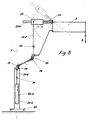
- the weight AGb is shown freely suspended. In practice this is of course in a cage, on a guide rod or in the Stand column of the tripod can be accommodated, such as in the Fig. 7 and 8 is indicated.
- FIG. 8 is a simplified structure according to FIG. 7 and is dispensed with on the roller 30, as well as on the bracket 207. Instead, only the attachment point of the cable 24d set on a slide shoe 23, the over the spindle 31 is displaceable along the compensating arm 22b. If necessary can one of the rollers 36, 37 as a gear roller according to the structure according to 3a be designed to have a step-up or step-down on the cable 24d to effect.
- FIG. 11 shows a tripod structure designed according to the invention a microscope as a load G on a swivel bracket 79 integrated by one constructed parallelogram 2b is held.
- the carrier 2b is on a bearing 119 of a horizontal arm 29 pivotally mounted on the the column 21 is mounted.
- a bow handle 88 serves as a transport aid and a device box 89 is used to hold controls, power supply, Illumination, etc. also as an additional tilt safety improvement according to the structure MS 1.
- a balance weight is always spoken of.
- other balancing force generators instead of the balancing weight Measures such as tension springs or the like. be provided can without leaving the essence of the invention. However, it is on it to ensure that these tension springs or the like. generate a constant balancing force.
- the invention also differs significantly from the known one State of the art US 5253832.
- the applicant's new inventive structure according to DE 200 19 106 offers an example of such force-compensated solution with a spring.
Landscapes
- Engineering & Computer Science (AREA)
- General Engineering & Computer Science (AREA)
- Mechanical Engineering (AREA)
- Health & Medical Sciences (AREA)
- Surgery (AREA)
- Physics & Mathematics (AREA)
- Life Sciences & Earth Sciences (AREA)
- Heart & Thoracic Surgery (AREA)
- Medical Informatics (AREA)
- Pathology (AREA)
- Nuclear Medicine, Radiotherapy & Molecular Imaging (AREA)
- General Physics & Mathematics (AREA)
- Biomedical Technology (AREA)
- Optics & Photonics (AREA)
- Oral & Maxillofacial Surgery (AREA)
- Molecular Biology (AREA)
- Animal Behavior & Ethology (AREA)
- General Health & Medical Sciences (AREA)
- Public Health (AREA)
- Veterinary Medicine (AREA)
- Microscoopes, Condenser (AREA)
- Studio Devices (AREA)
Applications Claiming Priority (2)
| Application Number | Priority Date | Filing Date | Title |
|---|---|---|---|
| DE20019105U DE20019105U1 (de) | 2000-11-12 | 2000-11-12 | Stativ |
| DE20019105U | 2000-11-12 |
Publications (2)
| Publication Number | Publication Date |
|---|---|
| EP1207334A1 true EP1207334A1 (fr) | 2002-05-22 |
| EP1207334B1 EP1207334B1 (fr) | 2006-06-14 |
Family
ID=7948652
Family Applications (1)
| Application Number | Title | Priority Date | Filing Date |
|---|---|---|---|
| EP01125606A Expired - Lifetime EP1207334B1 (fr) | 2000-11-12 | 2001-10-26 | Support |
Country Status (4)
| Country | Link |
|---|---|
| US (1) | US7000873B2 (fr) |
| EP (1) | EP1207334B1 (fr) |
| JP (1) | JP4041669B2 (fr) |
| DE (2) | DE20019105U1 (fr) |
Cited By (1)
| Publication number | Priority date | Publication date | Assignee | Title |
|---|---|---|---|---|
| DE102011056086A1 (de) * | 2011-12-06 | 2013-06-06 | Leica Microsystems (Schweiz) Ag | Stativ zum Halten von mindestens einem medizinischen Gerät, insbesondere einem Mikroskop |
Families Citing this family (26)
| Publication number | Priority date | Publication date | Assignee | Title |
|---|---|---|---|---|
| DE50111444D1 (de) * | 2000-09-28 | 2006-12-28 | Leica Microsystems Schweiz Ag | Stativ |
| DE20114343U1 (de) | 2000-09-30 | 2001-11-29 | Carl Zeiss, 89518 Heidenheim | Stativ |
| DE20019109U1 (de) * | 2000-11-12 | 2001-02-22 | Leica Microsystems Ag, Heerbrugg | Stativ, insbesondere für Operationsmikroskope |
| DE20019106U1 (de) | 2000-11-12 | 2001-02-22 | Leica Microsystems Ag, Heerbrugg | Stativ mit Parallelogrammträger und Balanciermechanismus |
| DE20019107U1 (de) | 2000-11-12 | 2001-01-25 | Leica Microsystems Ag, Heerbrugg | Stativ |
| DE20019105U1 (de) * | 2000-11-12 | 2001-05-23 | Leica Microsystems Ag, Heerbrugg | Stativ |
| DE10156318A1 (de) * | 2001-11-19 | 2003-05-28 | Zeiss Carl | Vorrichtung und Verfahren für wenigstens teilweisen Ausgleich eines Last-Drehmoments |
| DE50209535D1 (de) | 2002-01-04 | 2007-04-05 | Leica Microsystems Schweiz Ag | Stativ mit einer automatischen Balanciereinrichtung |
| FR2845889B1 (fr) * | 2002-10-22 | 2005-02-11 | Centre Nat Rech Scient | Robot chirurgical d'orientation et de positionnement d'un instrument chirurgical porteur d'un outil terminal chirurgical |
| US7837674B2 (en) * | 2005-01-24 | 2010-11-23 | Intuitive Surgical Operations, Inc. | Compact counter balance for robotic surgical systems |
| JP5350675B2 (ja) * | 2008-05-15 | 2013-11-27 | オリンパスメディカルシステムズ株式会社 | 医療用保持装置 |
| DE102008044028A1 (de) * | 2008-11-24 | 2010-08-12 | Cemecon Ag | Vorrichtung und Verfahren zum Beschichten eines Substrats mittels CVD |
| DE102011004926A1 (de) * | 2011-03-01 | 2012-09-06 | Karl Storz Gmbh & Co. Kg | Einstellbare Haltevorrichtung für ein Endoskop |
| US20120248273A1 (en) * | 2011-03-29 | 2012-10-04 | David Singer | Mounting system with adjustable height and load carrying surface |
| US8960632B2 (en) | 2011-07-05 | 2015-02-24 | Mediamounts, Ltd. | Dual bar linkage monitor support with adustment feature |
| JP5433089B2 (ja) * | 2013-02-12 | 2014-03-05 | オリンパスメディカルシステムズ株式会社 | 医療用保持装置 |
| US9623270B2 (en) * | 2014-06-25 | 2017-04-18 | Fall-Botics, Llc | Personal safety apparatus and system |
| WO2020181290A1 (fr) | 2019-03-07 | 2020-09-10 | Procept Biorobotics Corporation | Bras robotiques et méthodes de résection et d'imagerie de tissu |
| US10953536B2 (en) * | 2019-05-03 | 2021-03-23 | The Magstim Company Limited | Support arrangement for supporting a load in an elevated position |
| US11071601B2 (en) | 2019-11-11 | 2021-07-27 | Procept Biorobotics Corporation | Surgical probes for tissue resection with robotic arms |
| US12102851B2 (en) * | 2019-11-21 | 2024-10-01 | 3M Innovative Properties Company | Fall protection system |
| US11096753B1 (en) | 2020-06-26 | 2021-08-24 | Procept Biorobotics Corporation | Systems and methods for defining and modifying range of motion of probe used in patient treatment |
| US11877818B2 (en) * | 2020-06-26 | 2024-01-23 | Procept Biorobotics Corporation | Integration of robotic arms with surgical probes |
| US12178498B2 (en) | 2021-04-20 | 2024-12-31 | Procept Biorobotics Corporation | Surgical probe with independent energy sources |
| US12054364B2 (en) | 2021-10-21 | 2024-08-06 | Fall-Botics, Llc | Personal safety and fall protection systems |
| US20250223056A1 (en) | 2024-01-04 | 2025-07-10 | United Arab Emirates University | Low gravity simulator |
Citations (15)
| Publication number | Priority date | Publication date | Assignee | Title |
|---|---|---|---|---|
| DD221571A1 (de) * | 1984-02-01 | 1985-04-24 | Zeiss Jena Veb Carl | Drehgelenk mit einer einrichtung zur kompensation unterschiedlicher lastmomente |
| US4515333A (en) * | 1980-04-15 | 1985-05-07 | University Of Technology | Adjustable support for an optical or other instrument |
| FR2605757A1 (fr) * | 1986-10-27 | 1988-04-29 | Binet Alain | Reflecteur photographique |
| DE3739080A1 (de) | 1987-11-01 | 1989-05-11 | Stemme Otto | Federvorrichtung zum gewichtausgleich fuer stative |
| EP0433426A1 (fr) | 1989-07-04 | 1991-06-26 | Wild Heerbrugg Ag | Statif equipe de dispositifs accessoires, pour supporter un appareil librement orientable. |
| US5253832A (en) | 1991-07-26 | 1993-10-19 | Bolas Mark T | Spring counterbalanced boom suspension system |
| US5397323A (en) | 1992-10-30 | 1995-03-14 | International Business Machines Corporation | Remote center-of-motion robot for surgery |
| EP0700665A1 (fr) | 1994-09-12 | 1996-03-13 | Olympus Optical Co., Ltd. | Assemblage de microscope chirurgical |
| WO1997013997A1 (fr) | 1995-10-12 | 1997-04-17 | Leica Ag | Support |
| WO1999001693A1 (fr) | 1997-06-30 | 1999-01-14 | Leica Mikroskopie Systeme Ag | Contrepoids pour statif |
| DE19742050A1 (de) | 1997-09-24 | 1999-03-25 | Zeiss Carl Fa | Stativ mit Gewichtsausgleich |
| US6070839A (en) | 1997-03-20 | 2000-06-06 | Carl-Zeiss-Stiftung Trading As Carl Zeiss | Stand |
| DE20019107U1 (de) * | 2000-11-12 | 2001-01-25 | Leica Microsystems Ag, Heerbrugg | Stativ |
| DE20019106U1 (de) | 2000-11-12 | 2001-02-22 | Leica Microsystems Ag, Heerbrugg | Stativ mit Parallelogrammträger und Balanciermechanismus |
| DE20019105U1 (de) * | 2000-11-12 | 2001-05-23 | Leica Microsystems Ag, Heerbrugg | Stativ |
Family Cites Families (14)
| Publication number | Priority date | Publication date | Assignee | Title |
|---|---|---|---|---|
| DE221571C (fr) | ||||
| FR2181584B1 (fr) * | 1972-04-28 | 1977-07-22 | Luceat Sa | |
| FR2423424A1 (fr) * | 1978-04-20 | 1979-11-16 | Fmc Europe | Bras de chargement muni d'un dispositif de blocage hydraulique du tube externe. |
| DE7930125U1 (de) * | 1979-07-24 | 1980-01-24 | Contraves Ag, Zuerich (Schweiz) | Zusatzvorrichtung an einem stativ fuer ein optisches beobachtungsgeraet |
| JPS58117613U (ja) * | 1982-02-03 | 1983-08-11 | 東京光学機械株式会社 | 医療機器支持装置 |
| JPS58117611U (ja) * | 1982-02-03 | 1983-08-11 | 東京光学機械株式会社 | 医療機器支持装置 |
| US4685648A (en) * | 1985-05-17 | 1987-08-11 | Bausch & Lomb Incorporated | Counterbalancing apparatus for use in an optical instrument |
| JP2510636Y2 (ja) * | 1986-05-15 | 1996-09-18 | オリンパス光学工業株式会社 | 手術用顕微鏡 |
| US4738448A (en) * | 1987-02-09 | 1988-04-19 | Liester Arvin F | Support assembly for a basketball basket and backboard |
| US5746404A (en) * | 1996-02-15 | 1998-05-05 | Merko; Andrew V. | Apparatus for counterbalancing equipment |
| US6105909A (en) * | 1997-09-24 | 2000-08-22 | Carl-Zeiss-Stiftung | Stand with energy storage device for weight equalization |
| JPH11244301A (ja) * | 1998-02-27 | 1999-09-14 | Olympus Optical Co Ltd | 手術用顕微鏡 |
| US5984811A (en) * | 1998-06-03 | 1999-11-16 | Taylor; Bryce | Adjustable basketball standard |
| DE20114343U1 (de) * | 2000-09-30 | 2001-11-29 | Carl Zeiss, 89518 Heidenheim | Stativ |
-
2000
- 2000-11-12 DE DE20019105U patent/DE20019105U1/de not_active Expired - Lifetime
-
2001
- 2001-10-26 DE DE50110135T patent/DE50110135D1/de not_active Expired - Lifetime
- 2001-10-26 EP EP01125606A patent/EP1207334B1/fr not_active Expired - Lifetime
- 2001-11-08 US US10/010,101 patent/US7000873B2/en not_active Expired - Fee Related
- 2001-11-12 JP JP2001346733A patent/JP4041669B2/ja not_active Expired - Fee Related
Patent Citations (17)
| Publication number | Priority date | Publication date | Assignee | Title |
|---|---|---|---|---|
| US4515333A (en) * | 1980-04-15 | 1985-05-07 | University Of Technology | Adjustable support for an optical or other instrument |
| DD221571A1 (de) * | 1984-02-01 | 1985-04-24 | Zeiss Jena Veb Carl | Drehgelenk mit einer einrichtung zur kompensation unterschiedlicher lastmomente |
| FR2605757A1 (fr) * | 1986-10-27 | 1988-04-29 | Binet Alain | Reflecteur photographique |
| DE3739080A1 (de) | 1987-11-01 | 1989-05-11 | Stemme Otto | Federvorrichtung zum gewichtausgleich fuer stative |
| EP0433426A1 (fr) | 1989-07-04 | 1991-06-26 | Wild Heerbrugg Ag | Statif equipe de dispositifs accessoires, pour supporter un appareil librement orientable. |
| EP0433426B1 (fr) * | 1989-07-04 | 1994-02-02 | Leica AG | Statif equipe de dispositifs accessoires, pour supporter un appareil librement orientable |
| US5253832A (en) | 1991-07-26 | 1993-10-19 | Bolas Mark T | Spring counterbalanced boom suspension system |
| US5397323A (en) | 1992-10-30 | 1995-03-14 | International Business Machines Corporation | Remote center-of-motion robot for surgery |
| EP0700665A1 (fr) | 1994-09-12 | 1996-03-13 | Olympus Optical Co., Ltd. | Assemblage de microscope chirurgical |
| WO1997013997A1 (fr) | 1995-10-12 | 1997-04-17 | Leica Ag | Support |
| US6129319A (en) * | 1995-10-12 | 2000-10-10 | Leica Microsystems Ag | Automatically adjustable counterbalanced stand |
| US6070839A (en) | 1997-03-20 | 2000-06-06 | Carl-Zeiss-Stiftung Trading As Carl Zeiss | Stand |
| WO1999001693A1 (fr) | 1997-06-30 | 1999-01-14 | Leica Mikroskopie Systeme Ag | Contrepoids pour statif |
| DE19742050A1 (de) | 1997-09-24 | 1999-03-25 | Zeiss Carl Fa | Stativ mit Gewichtsausgleich |
| DE20019107U1 (de) * | 2000-11-12 | 2001-01-25 | Leica Microsystems Ag, Heerbrugg | Stativ |
| DE20019106U1 (de) | 2000-11-12 | 2001-02-22 | Leica Microsystems Ag, Heerbrugg | Stativ mit Parallelogrammträger und Balanciermechanismus |
| DE20019105U1 (de) * | 2000-11-12 | 2001-05-23 | Leica Microsystems Ag, Heerbrugg | Stativ |
Cited By (1)
| Publication number | Priority date | Publication date | Assignee | Title |
|---|---|---|---|---|
| DE102011056086A1 (de) * | 2011-12-06 | 2013-06-06 | Leica Microsystems (Schweiz) Ag | Stativ zum Halten von mindestens einem medizinischen Gerät, insbesondere einem Mikroskop |
Also Published As
| Publication number | Publication date |
|---|---|
| JP4041669B2 (ja) | 2008-01-30 |
| US7000873B2 (en) | 2006-02-21 |
| EP1207334B1 (fr) | 2006-06-14 |
| US20020121577A1 (en) | 2002-09-05 |
| DE50110135D1 (de) | 2006-07-27 |
| DE20019105U1 (de) | 2001-05-23 |
| JP2002207174A (ja) | 2002-07-26 |
Similar Documents
| Publication | Publication Date | Title |
|---|---|---|
| EP1207334A1 (fr) | Support | |
| DE10042272B4 (de) | Stativanordnung | |
| EP0855002B1 (fr) | Support | |
| EP0433426B1 (fr) | Statif equipe de dispositifs accessoires, pour supporter un appareil librement orientable | |
| EP1193439B1 (fr) | Support | |
| EP2962673A1 (fr) | Colonne de table d'opération pour table d'opération | |
| DE2920234A1 (de) | Gewichtsausgleicheinrichtung fuer roentgenroehrenhauben | |
| DE102008015210A1 (de) | Stativ zur Halterung und Positionierung einer Nutzlast im Raum | |
| EP1336885B1 (fr) | Système microscopique microchirurgical | |
| EP1336884B1 (fr) | Système de microscope microchirurgical | |
| DE102012220039B4 (de) | Durch Schwerkraft angetriebenes Ausgleichssystem | |
| EP1251380A2 (fr) | Statif pour un microscope d'opération | |
| DE7315186U (de) | Verstellbares stativ fuer ein optisches beobachtungsgeraet, insbesondere ein binokularmikroskop | |
| EP3973222A1 (fr) | Arrangement de maintien pour une caméra | |
| DE102010010131B4 (de) | Stativ für ein Mikroskop, insbesondere für ein Operationsmikroskop, und Verwendung eines solchen Stativs | |
| EP1205703B1 (fr) | Support,en particulier pour microscope chirurgical | |
| DE19742051B4 (de) | Stativ mit Energiespeicher zum Gewichtsausgleich | |
| DE19742050A1 (de) | Stativ mit Gewichtsausgleich | |
| CH692926A5 (de) | Stativ mit Energiespeicher zum Gewichtsausgleich. | |
| DE202020101821U1 (de) | Haltevorrichtung für eine Kamera | |
| DE102019113301B4 (de) | Haltevorrichtung für eine Kamera | |
| DE4244290C2 (de) | Hebe- und Umsetzhilfe mit Gewichtskraftausgleich | |
| EP1484112A2 (fr) | Support ajustable en hauteur, et méthode de découplage du système de maintien associé à ce support. | |
| DE2704528C2 (de) | Gegengewichtsausgleich für ein Röntgenuntersuchungsgerät | |
| DE4014003A1 (de) | Mechanischer momentenausgleich |
Legal Events
| Date | Code | Title | Description |
|---|---|---|---|
| PUAI | Public reference made under article 153(3) epc to a published international application that has entered the european phase |
Free format text: ORIGINAL CODE: 0009012 |
|
| AX | Request for extension of the european patent |
Free format text: AL;LT;LV;MK;RO;SI |
|
| 17P | Request for examination filed |
Effective date: 20021102 |
|
| AKX | Designation fees paid |
Designated state(s): DE FR GB |
|
| 17Q | First examination report despatched |
Effective date: 20041209 |
|
| GRAP | Despatch of communication of intention to grant a patent |
Free format text: ORIGINAL CODE: EPIDOSNIGR1 |
|
| GRAS | Grant fee paid |
Free format text: ORIGINAL CODE: EPIDOSNIGR3 |
|
| GRAA | (expected) grant |
Free format text: ORIGINAL CODE: 0009210 |
|
| AK | Designated contracting states |
Kind code of ref document: B1 Designated state(s): DE FR GB |
|
| REG | Reference to a national code |
Ref country code: GB Ref legal event code: FG4D Free format text: NOT ENGLISH |
|
| REF | Corresponds to: |
Ref document number: 50110135 Country of ref document: DE Date of ref document: 20060727 Kind code of ref document: P |
|
| GBT | Gb: translation of ep patent filed (gb section 77(6)(a)/1977) |
Effective date: 20060923 |
|
| ET | Fr: translation filed | ||
| PLBE | No opposition filed within time limit |
Free format text: ORIGINAL CODE: 0009261 |
|
| STAA | Information on the status of an ep patent application or granted ep patent |
Free format text: STATUS: NO OPPOSITION FILED WITHIN TIME LIMIT |
|
| 26N | No opposition filed |
Effective date: 20070315 |
|
| REG | Reference to a national code |
Ref country code: GB Ref legal event code: 732E Free format text: REGISTERED BETWEEN 20100304 AND 20100310 |
|
| REG | Reference to a national code |
Ref country code: FR Ref legal event code: CD |
|
| REG | Reference to a national code |
Ref country code: FR Ref legal event code: TP |
|
| REG | Reference to a national code |
Ref country code: FR Ref legal event code: PLFP Year of fee payment: 15 |
|
| PGFP | Annual fee paid to national office [announced via postgrant information from national office to epo] |
Ref country code: DE Payment date: 20151030 Year of fee payment: 15 |
|
| REG | Reference to a national code |
Ref country code: FR Ref legal event code: PLFP Year of fee payment: 16 |
|
| PGFP | Annual fee paid to national office [announced via postgrant information from national office to epo] |
Ref country code: FR Payment date: 20161027 Year of fee payment: 16 Ref country code: GB Payment date: 20161028 Year of fee payment: 16 |
|
| REG | Reference to a national code |
Ref country code: DE Ref legal event code: R119 Ref document number: 50110135 Country of ref document: DE |
|
| PG25 | Lapsed in a contracting state [announced via postgrant information from national office to epo] |
Ref country code: DE Free format text: LAPSE BECAUSE OF NON-PAYMENT OF DUE FEES Effective date: 20170503 |
|
| GBPC | Gb: european patent ceased through non-payment of renewal fee |
Effective date: 20171026 |
|
| REG | Reference to a national code |
Ref country code: FR Ref legal event code: ST Effective date: 20180629 |
|
| PG25 | Lapsed in a contracting state [announced via postgrant information from national office to epo] |
Ref country code: GB Free format text: LAPSE BECAUSE OF NON-PAYMENT OF DUE FEES Effective date: 20171026 |
|
| PG25 | Lapsed in a contracting state [announced via postgrant information from national office to epo] |
Ref country code: FR Free format text: LAPSE BECAUSE OF NON-PAYMENT OF DUE FEES Effective date: 20171031 |