EP0855355A2 - Machine d'enroulement et procédé pour l'enroulement continu d'un bande de matériel - Google Patents
Machine d'enroulement et procédé pour l'enroulement continu d'un bande de matériel Download PDFInfo
- Publication number
- EP0855355A2 EP0855355A2 EP97122390A EP97122390A EP0855355A2 EP 0855355 A2 EP0855355 A2 EP 0855355A2 EP 97122390 A EP97122390 A EP 97122390A EP 97122390 A EP97122390 A EP 97122390A EP 0855355 A2 EP0855355 A2 EP 0855355A2
- Authority
- EP
- European Patent Office
- Prior art keywords
- winding
- drum
- pressure drum
- transport device
- machine according
- Prior art date
- Legal status (The legal status is an assumption and is not a legal conclusion. Google has not performed a legal analysis and makes no representation as to the accuracy of the status listed.)
- Granted
Links
- 238000004804 winding Methods 0.000 title claims abstract description 277
- 239000000463 material Substances 0.000 title claims description 49
- 238000000034 method Methods 0.000 title claims description 41
- 238000012546 transfer Methods 0.000 claims description 9
- 238000006073 displacement reaction Methods 0.000 claims description 7
- 230000002093 peripheral effect Effects 0.000 claims description 6
- 238000003825 pressing Methods 0.000 claims description 6
- 230000033228 biological regulation Effects 0.000 claims description 5
- 239000011111 cardboard Substances 0.000 claims description 4
- 239000011087 paperboard Substances 0.000 claims description 4
- 238000007730 finishing process Methods 0.000 claims description 3
- 239000000109 continuous material Substances 0.000 claims description 2
- 230000015572 biosynthetic process Effects 0.000 claims 3
- 238000003860 storage Methods 0.000 description 36
- 230000001105 regulatory effect Effects 0.000 description 6
- 238000010276 construction Methods 0.000 description 5
- 230000001276 controlling effect Effects 0.000 description 4
- 238000010586 diagram Methods 0.000 description 2
- 239000000123 paper Substances 0.000 description 2
- 238000012545 processing Methods 0.000 description 2
- 238000011144 upstream manufacturing Methods 0.000 description 2
- 238000000418 atomic force spectrum Methods 0.000 description 1
- 238000007664 blowing Methods 0.000 description 1
- 230000000881 depressing effect Effects 0.000 description 1
- 238000013461 design Methods 0.000 description 1
- 239000013072 incoming material Substances 0.000 description 1
- 230000014759 maintenance of location Effects 0.000 description 1
- 238000004519 manufacturing process Methods 0.000 description 1
- 238000005259 measurement Methods 0.000 description 1
Images
Classifications
-
- B—PERFORMING OPERATIONS; TRANSPORTING
- B65—CONVEYING; PACKING; STORING; HANDLING THIN OR FILAMENTARY MATERIAL
- B65H—HANDLING THIN OR FILAMENTARY MATERIAL, e.g. SHEETS, WEBS, CABLES
- B65H19/00—Changing the web roll
- B65H19/22—Changing the web roll in winding mechanisms or in connection with winding operations
- B65H19/2207—Changing the web roll in winding mechanisms or in connection with winding operations the web roll being driven by a winding mechanism of the centre or core drive type
-
- B—PERFORMING OPERATIONS; TRANSPORTING
- B65—CONVEYING; PACKING; STORING; HANDLING THIN OR FILAMENTARY MATERIAL
- B65H—HANDLING THIN OR FILAMENTARY MATERIAL, e.g. SHEETS, WEBS, CABLES
- B65H18/00—Winding webs
- B65H18/08—Web-winding mechanisms
- B65H18/26—Mechanisms for controlling contact pressure on winding-web package, e.g. for regulating the quantity of air between web layers
-
- B—PERFORMING OPERATIONS; TRANSPORTING
- B65—CONVEYING; PACKING; STORING; HANDLING THIN OR FILAMENTARY MATERIAL
- B65H—HANDLING THIN OR FILAMENTARY MATERIAL, e.g. SHEETS, WEBS, CABLES
- B65H2301/00—Handling processes for sheets or webs
- B65H2301/30—Orientation, displacement, position of the handled material
- B65H2301/31—Features of transport path
- B65H2301/316—Features of transport path of web roll
- B65H2301/3164—Features of transport path of web roll involving at least two planes containing the roll axis
- B65H2301/31642—L-shaped
-
- B—PERFORMING OPERATIONS; TRANSPORTING
- B65—CONVEYING; PACKING; STORING; HANDLING THIN OR FILAMENTARY MATERIAL
- B65H—HANDLING THIN OR FILAMENTARY MATERIAL, e.g. SHEETS, WEBS, CABLES
- B65H2301/00—Handling processes for sheets or webs
- B65H2301/40—Type of handling process
- B65H2301/41—Winding, unwinding
- B65H2301/413—Supporting web roll
- B65H2301/4136—Mounting arrangements not otherwise provided for
- B65H2301/41361—Mounting arrangements not otherwise provided for sequentially used roll supports for the same web roll
-
- B—PERFORMING OPERATIONS; TRANSPORTING
- B65—CONVEYING; PACKING; STORING; HANDLING THIN OR FILAMENTARY MATERIAL
- B65H—HANDLING THIN OR FILAMENTARY MATERIAL, e.g. SHEETS, WEBS, CABLES
- B65H2301/00—Handling processes for sheets or webs
- B65H2301/40—Type of handling process
- B65H2301/41—Winding, unwinding
- B65H2301/414—Winding
- B65H2301/4144—Finishing winding process
- B65H2301/41441—Finishing winding process and blocking outer layers against falling apart
- B65H2301/41444—Specified by process phase during which sealing /securing is performed
- B65H2301/414443—Sealing or securing within the winding station
-
- B—PERFORMING OPERATIONS; TRANSPORTING
- B65—CONVEYING; PACKING; STORING; HANDLING THIN OR FILAMENTARY MATERIAL
- B65H—HANDLING THIN OR FILAMENTARY MATERIAL, e.g. SHEETS, WEBS, CABLES
- B65H2301/00—Handling processes for sheets or webs
- B65H2301/40—Type of handling process
- B65H2301/41—Winding, unwinding
- B65H2301/414—Winding
- B65H2301/4146—Winding involving particular drive arrangement
- B65H2301/41466—Winding involving particular drive arrangement combinations of drives
- B65H2301/41468—Winding involving particular drive arrangement combinations of drives centre and nip drive
-
- B—PERFORMING OPERATIONS; TRANSPORTING
- B65—CONVEYING; PACKING; STORING; HANDLING THIN OR FILAMENTARY MATERIAL
- B65H—HANDLING THIN OR FILAMENTARY MATERIAL, e.g. SHEETS, WEBS, CABLES
- B65H2403/00—Power transmission; Driving means
- B65H2403/50—Driving mechanisms
- B65H2403/52—Translation screw-thread mechanisms
-
- B—PERFORMING OPERATIONS; TRANSPORTING
- B65—CONVEYING; PACKING; STORING; HANDLING THIN OR FILAMENTARY MATERIAL
- B65H—HANDLING THIN OR FILAMENTARY MATERIAL, e.g. SHEETS, WEBS, CABLES
- B65H2408/00—Specific machines
- B65H2408/20—Specific machines for handling web(s)
- B65H2408/23—Winding machines
- B65H2408/2362—Winding machines with two secondary winding spools, e.g. on separate carriages
- B65H2408/2364—Winding machines with two secondary winding spools, e.g. on separate carriages with additional element for facilitating web roll change
Definitions
- the machine relates to a winding machine for continuous Winding a web of material, in particular Paper or cardboard web, according to the generic term of claim 1 and a method for continuous Winding a web of material, in particular Paper or cardboard web, according to the preamble of the claim 17th
- Winding machines and processes of the ones mentioned here kind are known from DE 196 07 349.
- the Known winding machine comprises a means of Pressure device movable pressure drum, the defined pressed on the circumference of a winding roll and forms a winding gap with it.
- the pressure drum is on a guide movable first transport device arranged.
- the winding machine includes a stationary secondary storage, which the reel during the finish winding process rotatable in a fixed position holds.
- the pressure drum becomes a drum change first vertically upwards into a takeover position proceed in which the pressure drum with a rotatable on the third transport device held empty drum forms a winding nip.
- the material web is now separated and its free one End wound on the empty reel, which then together with the pressure drum in the lower winding position is transferred.
- the second and the third transport device move vertically downwards.
- the new drum With the only having a few winding layers
- Winding roll driven by a primary drive. From the winding position is the winding roll move horizontally to a finished winding position, in which the primary drive is uncoupled and a secondary drive is coupled to the winding roll, the winding roll during the further winding process drives.
- the winding machine has a relative complex construction, in particular due to the independently relocatable second and third transport devices. Furthermore, has pointed out that the control of the displacement movements of the three transport facilities very much is complex.
- the object of the invention is a winding machine and to create a process that do not have these disadvantages.
- a relocation of the new drum on which it was wound so feasible in the stationary secondary storage be the desired level of line force in the winding nip with as little effort as possible remains intact during the aforementioned relocation.
- a winding machine is used to solve this task proposed the features of claim 1 having.
- This is characterized in that the Primary storage stationary on the transport device is arranged.
- the Primary storage and the pressure drum is one, common transport device assigned, whereby on the one hand, the construction of the winding machine and on the other hand simplifies their control can be.
- An embodiment of the winding machine is preferred, which is characterized in that during the winding roll is held by the secondary storage and being finished wrapped by a relocation the transport device carrying the pressure drum by means of a lifting device the larger increasing winding roll diameter is compensated. At the same time, the relative movement of the Pressure drum opposite the transport device the line force in the winding gap controlled / regulated.
- a control system is provided for this purpose with the pressure device, by means of which the pressure drum is relocatable, cooperates. The Relocation of the pressure drum relative to the transport device is used to adjust the Compressive forces in the winding gap between the pressure drum and the winding roll.
- the pressure drum has compared to the heavier with increasing diameter becoming winding roll a much lower weight so that a quick compensation of im Variations and jumps occurring in the winding gap the line force or the line force curve is possible. This is the line force extremely sensitive adjustable, resulting in a high Winding quality can be achieved.
- the control or regulation of the line force described above starts immediately when changing the reel and remains effective not only during the winding process, but also during the common Relocation of the wound drum into the Secondary storage (with the pressure drum on the shared transport facility easily) and during the subsequent finishing process.
- the main advantage of the invention is So in that the control of the line force during the winding process and during the transfer of the wound drum in the secondary storage alone in a simple and precise manner by moving the pressure drum by means of the pressure device on the transport device.
- the automatic retention of the desired Line force during the processes mentioned is thus possible without any additional effort. It is only sufficient during the finishing process maximum stroke of the pressure device as a rule not out, now the increasing winding roll diameter to follow. Then the (to move the transport device is necessary anyway) Lifting device already mentioned above effective to the Transport device (including the pressure drum, the pressure device and now empty Primary storage) gradually from the secondary storage pull away, according to the increase in the winding roll diameter.
- the primary storage Primary drive preferably center drive, for the winding roll is assigned, by means of which a defined torque on the from the primary bearing held drum can be applied.
- the primary drive is preferably stationary, that means stationary, arranged on the transport device, whereby the construction of the winding machine continues can be simplified, since additional guide and transport devices for the primary drive are not needed.
- the primary drive on a separate transport device to arrange and when transferring the from the Primary bearing rotatably held winding roll to the secondary storage parallel to the primary storage to relocate with. It is important that the drum torque during the entire winding process can be applied. This can work together with the control described above or Regulation of the line force in the winding gap - one winding roll with a defined, preferably uniform winding hardness can be produced.
- a method is also used to achieve the stated object for the continuous winding of a material web suggested that those mentioned in claim 17 Features. This is characterized by it from that the material web first over a Peripheral area of a pressure drum is guided, which forms a winding nip with a winding roll. To prepare a drum change, a free pull of the material web between the pressure drum and the almost finished winding roll and an empty drum in the area of the free movement brought into a winding position. Then there is a winding gap between the pressure drum and the empty drum by relocation the pressure drum against one the pressure drum and the transport device carrying the drum. The material web is then separated and their free end on the empty drum wound up.
- the winding roll in its winding position, with immediate control the line force begins in the winding nip.
- the pressure drum is defined relatively relocated to the transport device. After reaching a desired winding roll diameter, only a little in a preferred embodiment is larger than the diameter of the drum the winding roll is transferred to a finished winding position, in which the winding roll during the finish winding process held stationary rotatably is. During the transfer, this is said Controlling / regulating the line force continued continuously. Even while the winding roll is now in is its finished winding position, the line force in the winding gap by a relative movement the pressure drum opposite the pressure drum carrying transport device controlled / regulated.
- the growing one Coil diameter at the same time by a relative movement opposite the transport device a basis, for example a foundation on which the winding machine is balanced.
- a basis for example a foundation on which the winding machine is balanced.
- the winding machine described below is generally used for winding a material web.
- the winding machine can be at the end of a machine for the production or finishing of a material web, for example a paper web to convert the finished material web into a Wind up the winding roll.
- the winding machine can but can also be used to also referred to as a winding roll Roll over the wrap.
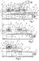
- Figures 1 to 3 each show a side view an embodiment of a winding machine 1, which is used to wind up a material web 3, for example a paper web, on a drum serves. This can be, for example, of a tubular Roll are formed. From Figures 1 to 3 is a sequence of functional steps of the Winding machine 1 out.
- the winding machine 1 also includes a carriage designated transport device 5, which on a Guide rails 7 comprising first guide 9 is movable.
- the guide rails 7 are on one a base 11 standing winding frame 13 attached and parallel to an imaginary, dashed illustrated horizontal H aligned.
- the procedure the transport device 5 on the first Guide 9 is only shown in FIG. 1
- Lifting device 10 provided, by means of which the transport device 5 in the horizontal direction (Double arrow 15) is shiftable.
- the one on the changing frame 13 attached lifting device 10 is from here formed a spindle drive, one of a Motor 12 includes a driven threaded spindle 14.
- As Lifting device can also be, for example hydraulic piston / cylinder unit used will.
- the primary bearing 17 stationary arranged to hold or the rotatable recording of a reel during the Starting process is used.
- the primary bearing 17 has So a fixed, unchangeable position on the Transport device 5 on. With “winding process” is the phase of the winding process, in who kept a drum from the primary bearing 17 becomes.
- a backup roller Press drum 19 provided on a Guide carriage 20 is rotatably held, the second guide comprising a rail 21 23 is movable.
- the Rails 21 are attached to the transport device 5 and preferably run in parallel, at least but essentially parallel to the guide rails 7 of the first guide 9.
- the guide carriage 20 is by means of on the transport device 5 attached pressing device 22 the rails 21 movable (double arrow 25).
- the Pressure device 22 is here as - preferably hydraulic piston / cylinder unit, which comprises a piston guided in a cylinder. A piston rod is attached to the piston, the other end with the sled 20 or the attached Storage of the pressure drum 19 is connected.
- the configuration of the pressing device 22 is fundamental variable, that is, with another In the exemplary embodiment, the pressing device 22 for example formed by a spindle drive will.
- the pressure drum 19 can from one in the Figures 1 to 3 center drive, not shown driven, that is, with an adjustable drive torque be admitted to the stationary the transport device 5 is arranged.
- the winding machine 1 further comprises a stationary one arranged secondary bearing 27 on the Wrapping frame 13 is attached.
- the secondary storage 27 is used for rotatable holding and guiding of a journal 28 having drum during of the finish winding process.
- Winding phase is on one of the secondary storage 27 drum 29 held continuously incoming material web 3 to a winding roll 31 wound up. With “ready winding process” is the part of the winding process called which the winding roll is held by the secondary bearing 27 becomes.
- the secondary bearing 27 is a assigned to a symbol indicated secondary drive 32, that held by the secondary bearing 27 Drum drives.
- the one as a center drive trained secondary drive 32 is on the winding frame 13 attached and therefore points within the Winding machine 1 a fixed position.
- the primary bearing 17 is only one primary drive 33 indicated with a symbol assigned to each of the primary storage 17 held drum with a defined Torque applied.
- the primary drive 33 is stationary the transport device 5 arranged so that at a shift of the transport device 5 of the Primary drive 33 relocated together with this becomes. So there will be no additional guidance for the primary drive 33 required, which makes the structure the winding machine and its control simplified can be.
- the primary drive 33 parallel to the rails 21 of the second guide 23 displaceable is independent of the relocation movement the transport device 5.
- the material web 3 from that of the winding machine 1 in the direction of rotation Material web 3 (arrow 34) seen- upstream Manufacturing or processing machine first guided over a stationary deflection roller 35 and by this to a rotatable on the transport device 5 stored deflection roller 37 out. From this is the material web 3 below one the pressure drum 19 arranged, shown in dashed lines third deflection roller 39 on the pressure drum 19 out.
- the deflection roller 39 is preferred designed as an spreader roller.
- the web of material 3 is over a peripheral region of the pressure drum 19 of approximately 180 ° and to that of the secondary bearing 27 held winding roller 31st wound up.
- the pressure drum 19 is with a defined force on the circumference of the winding roll 31st pressed so that a winding gap is formed, through which the material web 3 is guided. They too referred to as clamping pressure or force Line force in the winding gap is caused by a shift the pressure drum 19 on the second guide 23 controlled in the direction of the double arrow 25.
- the line force in the winding gap is regulated, that is, the line force is automatically on a desired value.
- the pressing device 22, with which the Pressure drum 19 cooperating guide carriage 20 cooperates defined influenced.
- Exemplary are a measuring device 67 and a in Figure 1 Control or regulation unit 68 schematically indicated.
- Winding roll 31 is one over the entire Width of the winding roll 31 extending, also as Squeeze roller 41 arranged pressure roller arranged, by means of a guide device, not shown relocatable and to the extent of with the pressure drum 19 forming a winding nip Winding roll 31 can be pressed.
- the squeeze roller 41 is used to introduce Air between the winding layers of the winding roller 31 prevent, for example, when the material web 3 is performed in a free move.
- the contact pressure, with the squeeze roller 41 to the circumference the winding roller 31 is pressed is adjustable.
- the squeeze roller 41 can be driven by a drive, for example, a center drive be, preferably before and during the squeeze roller 41 to the extent of the secondary storage 27 held winding roller 31 pressed becomes.
- the material web 3 is on the pressure drum 19th performed and on those held by the secondary bearing 27 Winding roll 31 wound ( Figure 1). Before the winding roller 31 its final / target diameter reached, the squeeze roller 41 to the periphery the winding roller 31 pressed ( Figure 2). The web of material 3 is thereby both through the winding gap between pressure drum 19 and winding roller 31 as also through the winding gap between the squeeze roller 41 and winding roller 31 out.
- the duration of the start-up process i.e. how long a winding roll guided by the primary bearing 17 is, is variable and can, for example, very much be short so that the winding roll is only one relative has small diameter increase.
- the exemplary embodiment is the maximum stroke of the piston less than half the material layer thickness a finished winding roll.
- the winding roll is now from the The winding position is transferred to the finished winding position and wrapped up here. During these operations becomes the control of the line force in the winding gap by a relative movement of the pressure drum opposite the one that carries the pressure drum Transport device continued continuously.
- the larger winding roll diameter the winding roll in the finished winding position is now preferably additionally by a Relative movement of the transport device opposite a base on which shown in Figures 1 to 3 Embodiment of the foundation 11, balanced.
- the maximum piston stroke Pressure device 22 relatively be kept small.
- Figure 4 shows schematically a top view of the winding machine described with reference to Figures 1 to 3 1.
- the same parts have the same reference numerals provided so that in this respect to the description is referred to the previous figures.
- the functional position shown in Figure 4 Winding machine 1 corresponds to that shown in FIG Functional position.
- the winding frame 13 has an outer part 13/1 and an inner part Part 13/2 on. On the outer part 13/1 of the Winding frame 13 are the guide rails 7 of the first guide 9 attached.
- the center drive 48 On the drive side of the winding machine 1 is a the pressure drum 19 cooperating center drive 48 arranged by means of which the rotatable mounted pressure drum 19 with a torque is acted upon.
- the center drive 48 is on one attached to the transport device 5 Console 49 attached and includes a motor 51 and a propeller shaft 53 which with a journal of the Pressure drum 19 is effectively connected.
- the pressure drum 19 on the guide rails 7 opposite the Transport device 5 and thus the stationary on it arranged motor 51 perform a relative movement can without interrupting the drive train, that is, the propeller shaft 53 from the pressure drum or the engine must be disconnected.
- the pressure drum 19 is therefore permanent with a torque actable.
- the primary drive 33 comprises a motor 57, the - as indicated by a double arrow 59 - with the drum 43 guided by the primary bearing 17 can be coupled.
- the primary drive 33 comprises a motor 63 which, as with a Double arrow 65 indicated - with that of the secondary storage 27 held drum 29 detachable is.
- the secondary drive 32 of the drum 29 on the finished winding roll 31 is wound up, Cut.
- the winding roll 31 is from the secondary storage 27 spread so that the primary storage 17 held and by the primary drive 33 driven drum 43 can be recorded. This is due to a relocation of the transport facility 5 in the direction of arrow 34 from the in Figure 4 shown winding position in the finished winding position transferred. Then a handover takes place of the reel 43 from the primary bearing 17 the secondary storage 27 instead.
- the secondary drive 32 coupled with the reel 43.
- the functional position shown in FIG. 3 results the winding machine 1, in which both the Primary drive 33 and the secondary drive 32 coupled simultaneously with the Drum 43, the means effectively connected.
- the primary drive 33 of the Drum 43 uncoupled and by moving the Transport device 5 moved back to the takeover position, in which an empty drum from the Primary storage 17 can be taken over.
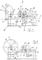
- Figures 5 and 6 schematically show a side view a further embodiment of the winding machine 1. Parts that match those in previous Figures match, are the same Provide reference numerals so that on the description can be referred to Figures 1 to 4. in the following is only intended to explain the differences To be received.
- the material web 3 is from one of the winding machine 1 upstream processing station for the Material web led to a guide roller 39 'and from this vertically upwards to a pressure drum 19 ', the one in the winding position Winding roll 47 forms a winding gap.
- the preceding finished winding roll 31 (with reel 29) is just from the winding machine in Figure 5 away.
- the pressure drum 19 ' is in the figure 5 illustrated embodiment of a Pressure roller formed, which is a relatively small Has outer diameter. This is clear smaller than the outside diameter of that in the figures 1 to 4 shown pressure drum 19.
- a displacement device on the guide carriage 20 70 arranged one on the guide carriage 20 has a fixed guide frame 72, for guiding a vertical slide 74 serves in the direction of a double arrow 76.
- the pressure drum 19 ' is rotatable on the vertical slide 74 held and by means of a not shown Center drive driven, which preferably arranged stationary on the vertical slide 74 is.
- Center drive driven which preferably arranged stationary on the vertical slide 74 is.
- the vertical Displacement of the pressure drum 19 ' is preferred relatively small and corresponds in particular one to two times the diameter of the pressure drum 19 '.
- the empty reel 43 can during the winding process be transferred to the primary bearing 17, without being rotated beforehand; because he does not come into contact with the running material web.
- the winding roller 31 is braked and then removed.
- the transport device moves 5 in Figure 5 to the left and passes the wound new drum 43/47 to the Secondary storage 27; this condition corresponds to the Figure 3.
- the empty drum is in the embodiment shown in Figures 5 and 6 by means of the (preferably stationary the transport device 5 arranged) primary drive 33 on the running speed of the material web accelerated and by this even after the reel change driven for a period of time.
- the empty drum from the standby position down to the winding level can be lowered and only here to web speed is accelerated.
- the center drive for the do not empty the drum vertically only horizontally need to be moved is preferred Embodiment provided that only one of the two center drives each Drum assigned during the entire winding process is, which increases the winding quality.
- the primary drive 33 and the secondary drive must be used 32 -independent of each other and of the transport device 5 can be moved horizontally be.
- the winding machine 1 of the secondary storage 27 assigned a winding support 78 which the winding roller held by the secondary bearing 27 supported on the outside over a circumferential area, that is relieved so that it does not sag or the deflection is only slight.
- the winding support arranged below the secondary bearing 27 78 can, for example, two pulleys and at least one revolving one above it Have tape.
- the structure of the winding support 78 is variable. There are therefore other constructions the changing support possible. By supporting the winding roll while it is in the finished winding position located, the winding quality be improved.
- the pressure drum 19 in its bearings Has measuring sensors 67 for the bearing forces, depending on the measurement signals Measuring sensors by means of a control or regulating device 68 the contact pressure is controlled with the the pressure drum 19 to the extent of an empty Drums 29 or 43 and then on the wound on the winding roll 31 or 47 pressed becomes.
Landscapes
- Replacement Of Web Rolls (AREA)
- Winding Of Webs (AREA)
Applications Claiming Priority (4)
| Application Number | Priority Date | Filing Date | Title |
|---|---|---|---|
| DE19702715A DE19702715A1 (de) | 1997-01-25 | 1997-01-25 | Verfahren und Vorrichtung zum Aufwickeln einer laufenden Faserstoffbahn |
| DE19702715 | 1997-01-25 | ||
| DE19745005A DE19745005A1 (de) | 1997-01-25 | 1997-10-11 | Wickelmaschine und Verfahren zum kontinuierlichen Aufwickeln einer Materialbahn |
| DE19745005 | 1997-10-11 |
Publications (3)
| Publication Number | Publication Date |
|---|---|
| EP0855355A2 true EP0855355A2 (fr) | 1998-07-29 |
| EP0855355A3 EP0855355A3 (fr) | 1999-03-10 |
| EP0855355B1 EP0855355B1 (fr) | 2005-03-09 |
Family
ID=26033393
Family Applications (1)
| Application Number | Title | Priority Date | Filing Date |
|---|---|---|---|
| EP97122390A Expired - Lifetime EP0855355B1 (fr) | 1997-01-25 | 1997-12-18 | Machine d'enroulement et procédé pour l'enroulement continu d'un bande de matériel |
Country Status (4)
| Country | Link |
|---|---|
| US (1) | US5967449A (fr) |
| EP (1) | EP0855355B1 (fr) |
| AT (1) | ATE290504T1 (fr) |
| CA (1) | CA2227302A1 (fr) |
Cited By (5)
| Publication number | Priority date | Publication date | Assignee | Title |
|---|---|---|---|---|
| WO2000012418A1 (fr) * | 1998-08-26 | 2000-03-09 | Metso Paper, Inc. | Procede relatif a des stations de bobinage en sequence et chaine de fabrication comportant de telles stations de bobinage en sequence |
| EP0921085A3 (fr) * | 1997-12-08 | 2000-05-31 | Voith Sulzer Papiertechnik Patent GmbH | Procédé et machine d'enroulage pour enrouler en continu une bande de matière |
| EP1238933A1 (fr) * | 1997-05-16 | 2002-09-11 | Voith Paper Patent GmbH | Méthode et dispositif pour continuellement enrouler une bande de matériau |
| DE10342020A1 (de) * | 2003-09-12 | 2005-04-07 | Voith Paper Patent Gmbh | Wickelmaschine zum Wickeln einer Materialbahn |
| EP2119653A1 (fr) * | 2008-05-14 | 2009-11-18 | ACHENBACH BUSCHHÜTTEN GmbH | Bobineuse destinée à enrouler une bande de feuille fine, notamment une bande d'aluminium |
Families Citing this family (25)
| Publication number | Priority date | Publication date | Assignee | Title |
|---|---|---|---|---|
| FI110424B (fi) * | 1998-06-18 | 2003-01-31 | Metso Paper Inc | Rullain ja menetelmä rainan rullaamiseksi |
| FI105467B (fi) * | 1998-10-16 | 2000-08-31 | Valmet Corp | Menetelmä konerullan pysäyttämiseksi |
| DE19848816A1 (de) | 1998-10-22 | 2000-04-27 | Voith Sulzer Papiertech Patent | Wickelmaschine |
| US6427938B1 (en) * | 1998-10-22 | 2002-08-06 | Voith Sulzer Papiertechnik Patent Gmbh | Process and apparatus for cutting a running material web |
| DE19848815A1 (de) | 1998-10-22 | 2000-04-27 | Voith Sulzer Papiertech Patent | Wickelmaschine |
| FI990982A0 (fi) | 1999-04-30 | 1999-04-30 | Valmet Corp | Menetelmä paperirainan rullausprosessissa |
| DE19923930A1 (de) * | 1999-05-26 | 2000-11-30 | Voith Sulzer Papiertech Patent | Vorrichtung zum Aufwickeln einer Materialbahn |
| DE10030199A1 (de) * | 2000-06-20 | 2002-01-03 | Voith Paper Patent Gmbh | Verfahren und Wickelmaschine zum kontinuierlichen Aufwickeln einer Materialbahn |
| FI115520B (fi) * | 2000-10-27 | 2005-05-31 | Metso Paper Inc | Menetelmä rullauksessa ja kiinnirullain |
| CA2436949C (fr) * | 2000-12-28 | 2008-04-22 | M & J Fibretech A/S | Appareil permettant d'enrouler une bande sur des bobines et procede pour decouper une certaine longueur de la bande |
| AT411590B (de) * | 2001-11-09 | 2004-03-25 | Andritz Ag Maschf | Verfahren und vorrichtung zum kontinuierlichen aufwickeln einer faserstoffbahn |
| DE10144016A1 (de) | 2001-09-07 | 2003-03-27 | Voith Paper Patent Gmbh | Verfahren und Wickelmaschine zum Aufwickeln einer Materialbahn |
| GB0221493D0 (en) * | 2002-09-17 | 2002-10-23 | Glaxo Group Ltd | Method for loading a medicament dispenser with a medicament carrier |
| FI117699B (fi) * | 2003-03-12 | 2007-01-31 | Metso Paper Inc | Menetelmä ja rullain paperi- tai kartonkirainan rullauksessa |
| FR2865722B1 (fr) * | 2004-02-02 | 2006-12-01 | Monomatic Sa | Dispositif d'enroulement a deux rouleaux d'entrainement pour machine a enrouler en continu et procede d'enroulement avec regulation de l'effort d'application des rouleaux d'entrainement |
| DE102004049720A1 (de) * | 2004-10-11 | 2006-04-20 | Voith Paper Patent Gmbh | Verfahren zum Einführen einer Materialbahn in eine Rollenwickeleinrichtung und Rollenwickeleinrichtung |
| EP2298676A1 (fr) * | 2009-09-17 | 2011-03-23 | The Procter & Gamble Company | Dispositif pelable pour dévider une toile de matériau d'un rouleau |
| DE102013220856A1 (de) * | 2013-10-15 | 2015-04-16 | Windmöller & Hölscher Kg | Wickeleinrichtung zum Aufwickeln eines bahnförmigen Materials und Verfahren zum Wechsel eines Wickels in einer Wickeleinrichtung |
| PL3109192T3 (pl) * | 2015-06-26 | 2020-10-19 | Valmet Technologies Oy | Nawijarka do nawijania włóknistej wstęgi |
| DK3626657T3 (da) | 2018-09-19 | 2021-04-19 | Sahm Georg Fa | Spolemaskine |
| DE102018008127B4 (de) | 2018-10-13 | 2022-06-09 | Hosokawa Alpine Aktiengesellschaft | Blaskopf und Verfahren zur Herstellung einer Mehrschichtschlauchfolie |
| DE102018009632B4 (de) * | 2018-12-11 | 2021-12-09 | Hosokawa Alpine Aktiengesellschaft | Vorrichtung zum Aufwickeln und Wickelwechsel von bahnförmigem Material und ein Verfahren dafür |
| DE102020000334A1 (de) | 2020-01-21 | 2021-07-22 | Hosokawa Alpine Aktiengesellschaft | Vorrichtung und Verfahren zur monaxialen Längenänderung von Folienbahnen |
| DE102021119724A1 (de) * | 2021-07-29 | 2023-02-02 | Brückner Maschinenbau GmbH & Co. KG | Folienaufwickelsystem, Verbund aus einer Folienreckanlage und einem solchen Folienaufwickelsystem und Verwendung eines solchen Verbunds zur Herstellung von Dünnstfilmen und Membranen |
| DE102022000351A1 (de) | 2022-01-29 | 2023-08-03 | Hosokawa Alpine Aktiengesellschaft | Verfahren und Vorrichtung zur Foliendickenregelung von gereckter im Folienblasverfahren hergestellter Schlauchfolie |
Family Cites Families (15)
| Publication number | Priority date | Publication date | Assignee | Title |
|---|---|---|---|---|
| DE697347C (de) * | 1938-07-26 | 1940-10-11 | Radebeuler Maschinenfabrik Aug | Aufrollvorrichtung fuer Papier- oder aehnliche Bahnen |
| BR8008746A (pt) * | 1979-07-09 | 1981-04-28 | Rieter Ag Maschf | Aparelho para a separacao de uma camada de fibras, de fibras para fio |
| DE3347733A1 (de) * | 1983-12-31 | 1985-11-07 | Lenze GmbH & Co KG Aerzen, 3258 Aerzen | Kontaktwalzensteuerung fuer aufwickelvorrichtung |
| FI91383C (fi) * | 1990-10-26 | 1997-01-22 | Valmet Paper Machinery Inc | Menetelmä kiinnirullauksessa |
| SE469071B (sv) * | 1991-09-18 | 1993-05-10 | Valmet Karlstad Ab | Rullstol med centrumdriven upprullningsvals |
| CH685767A5 (de) * | 1992-10-08 | 1995-09-29 | Rieter Ag Maschf | Maschine zum Bilden von Wattewickeln für Kämmaschinen. |
| DE4304469A1 (de) * | 1993-02-15 | 1994-08-18 | Erwin Cichon | Wickelvorrichtung mit Rollenwechseleinrichtung für aufzuwickelndes bandförmiges Wickelgut |
| US5370327A (en) * | 1993-05-06 | 1994-12-06 | Beloit Technologies, Inc. | Method and apparatus for reeling a wound web roll |
| AT402056B (de) * | 1993-08-18 | 1997-01-27 | Chemiefaser Lenzing Ag | Wickelmaschine |
| DE4401959C2 (de) * | 1994-01-24 | 1996-07-25 | Voith Gmbh J M | Tragtrommelroller für eine Papiermaschine |
| DE4415324C2 (de) * | 1994-05-02 | 1996-07-18 | Kleinewefers Gmbh | Vorrichtung zum Aufwickeln einer kontinuierlich zulaufenden Bahn, insbesondere Papierbahn |
| FI95683C (fi) * | 1994-06-10 | 1996-03-11 | Valmet Corp | Menetelmä ja laite rainan rullauksessa muodostuvan konerullan pintakerroksien viimeistelemiseksi |
| US5544841A (en) * | 1994-08-18 | 1996-08-13 | Beloit Technologies, Inc. | Method and apparatus for reeling a traveling web into a wound web roll |
| US5560566A (en) * | 1994-11-14 | 1996-10-01 | Beloit Technologies, Inc. | Winder with elevated spool support rail |
| US5673870A (en) * | 1995-12-19 | 1997-10-07 | Beloit Technologies, Inc. | Method and apparatus for reeling a traveling paper web |
-
1997
- 1997-12-18 AT AT97122390T patent/ATE290504T1/de not_active IP Right Cessation
- 1997-12-18 EP EP97122390A patent/EP0855355B1/fr not_active Expired - Lifetime
-
1998
- 1998-01-19 CA CA002227302A patent/CA2227302A1/fr not_active Abandoned
- 1998-01-26 US US09/012,956 patent/US5967449A/en not_active Expired - Fee Related
Cited By (6)
| Publication number | Priority date | Publication date | Assignee | Title |
|---|---|---|---|---|
| EP1238933A1 (fr) * | 1997-05-16 | 2002-09-11 | Voith Paper Patent GmbH | Méthode et dispositif pour continuellement enrouler une bande de matériau |
| EP0921085A3 (fr) * | 1997-12-08 | 2000-05-31 | Voith Sulzer Papiertechnik Patent GmbH | Procédé et machine d'enroulage pour enrouler en continu une bande de matière |
| WO2000012418A1 (fr) * | 1998-08-26 | 2000-03-09 | Metso Paper, Inc. | Procede relatif a des stations de bobinage en sequence et chaine de fabrication comportant de telles stations de bobinage en sequence |
| DE10342020A1 (de) * | 2003-09-12 | 2005-04-07 | Voith Paper Patent Gmbh | Wickelmaschine zum Wickeln einer Materialbahn |
| EP2119653A1 (fr) * | 2008-05-14 | 2009-11-18 | ACHENBACH BUSCHHÜTTEN GmbH | Bobineuse destinée à enrouler une bande de feuille fine, notamment une bande d'aluminium |
| DE102008023604A1 (de) * | 2008-05-14 | 2009-11-19 | ACHENBACH BUSCHHüTTEN GMBH | Wickelmaschine zum Aufwickeln von dünnem Folienband, insbesondere von Aluminiumband |
Also Published As
| Publication number | Publication date |
|---|---|
| US5967449A (en) | 1999-10-19 |
| ATE290504T1 (de) | 2005-03-15 |
| EP0855355B1 (fr) | 2005-03-09 |
| EP0855355A3 (fr) | 1999-03-10 |
| CA2227302A1 (fr) | 1998-07-25 |
Similar Documents
| Publication | Publication Date | Title |
|---|---|---|
| EP0855355B1 (fr) | Machine d'enroulement et procédé pour l'enroulement continu d'un bande de matériel | |
| EP0941955B1 (fr) | Méthode et dispositif pour continuellement enrouler une bande de matériau | |
| EP0912435B1 (fr) | Procede de bobinage continu d'une bande de materiau et bobineuse correspondante | |
| DE69507490T2 (de) | Verfahren und vorrichtung zum aufwickeln einer laufenden bahn in eine bahnrolle | |
| DE3539980C2 (de) | Verfahren und Vorrichtung zur Steuerung eines Papierbahnaufrollers | |
| EP0921085B1 (fr) | Procédé et machine d'enroulage pour enrouler en continu une bande de matière | |
| EP0826615B1 (fr) | Méthode et dispositif pour enrouler une bande de papier en un rouleau | |
| EP0792829B1 (fr) | Procédé pour enrouler une bande de papier en un rouleau | |
| EP0680911B1 (fr) | Dispositif pour enrouler une bande arrivant d'une manière continue, notamment une bande de papier | |
| DE69712354T2 (de) | Aufwickelvorrichtung mit doppelten sekundäreinheiten zum wickeln einer laufenden bahn in einer papiermaschine | |
| DE4104635A1 (de) | Vorrichtung zum aufrollen von bahn- oder bandfoermigen materialien | |
| DE3216182C2 (de) | Kalander für Papier- und andere Materialbahnen | |
| EP0450311A1 (fr) | Enrouleur pour feuilles continues | |
| DE19745005A1 (de) | Wickelmaschine und Verfahren zum kontinuierlichen Aufwickeln einer Materialbahn | |
| DE19735590A1 (de) | Wickelmaschine zum Aufwickeln einer Materialbahn | |
| EP1238933B1 (fr) | Méthode et dispositif pour continuellement enrouler une bande de matériau | |
| DE3221929A1 (de) | Verfahren zum beeinflussen der wickelhaerte beim wickeln von bahnfoermigem gut, insbesondere papierbahnen, sowie doppeltragwalzen-wickelmaschinen zur durchfuehrung des verfahrens | |
| DE60009917T2 (de) | Verfahren zum kontinuierlichen aufwickeln von papier und wickler | |
| EP0887293B1 (fr) | Dispositif de coupe à rouleaux pour une bande de matière | |
| DE19737709A1 (de) | Wickelmaschine zum kontinuierlichen Aufwickeln einer Materialbahn | |
| DE69918429T2 (de) | Vorrichtung und verfahren zum aufbringen einer last auf eine rolle beim aufrollen einer papierbahn | |
| DE19748995A1 (de) | Verfahren und Wickelmaschine zum kontinuierlichen Aufwickeln einer Materialbahn | |
| DE60118964T2 (de) | Vorrichtung und verfahren zum wickeln von bahnen | |
| EP1414726B1 (fr) | Procede et bobineuse destines a l'enroulement continu d'une bande de materiau | |
| DE60109323T2 (de) | Vorrichtung und verfahren zum wickeln von bahnen |
Legal Events
| Date | Code | Title | Description |
|---|---|---|---|
| PUAI | Public reference made under article 153(3) epc to a published international application that has entered the european phase |
Free format text: ORIGINAL CODE: 0009012 |
|
| AK | Designated contracting states |
Kind code of ref document: A2 Designated state(s): AT DE FI FR GB SE |
|
| AX | Request for extension of the european patent |
Free format text: AL;LT;LV;MK;RO;SI |
|
| PUAL | Search report despatched |
Free format text: ORIGINAL CODE: 0009013 |
|
| AK | Designated contracting states |
Kind code of ref document: A3 Designated state(s): AT BE CH DE DK ES FI FR GB GR IE IT LI LU MC NL PT SE |
|
| AX | Request for extension of the european patent |
Free format text: AL;LT;LV;MK;RO;SI |
|
| 17P | Request for examination filed |
Effective date: 19990910 |
|
| AKX | Designation fees paid |
Free format text: AT DE FI FR GB SE |
|
| RAP1 | Party data changed (applicant data changed or rights of an application transferred) |
Owner name: VOITH PAPER PATENT GMBH |
|
| GRAP | Despatch of communication of intention to grant a patent |
Free format text: ORIGINAL CODE: EPIDOSNIGR1 |
|
| GRAS | Grant fee paid |
Free format text: ORIGINAL CODE: EPIDOSNIGR3 |
|
| GRAA | (expected) grant |
Free format text: ORIGINAL CODE: 0009210 |
|
| AK | Designated contracting states |
Kind code of ref document: B1 Designated state(s): AT DE FI FR GB SE |
|
| PG25 | Lapsed in a contracting state [announced via postgrant information from national office to epo] |
Ref country code: GB Free format text: LAPSE BECAUSE OF FAILURE TO SUBMIT A TRANSLATION OF THE DESCRIPTION OR TO PAY THE FEE WITHIN THE PRESCRIBED TIME-LIMIT Effective date: 20050309 |
|
| REG | Reference to a national code |
Ref country code: GB Ref legal event code: FG4D Free format text: NOT ENGLISH |
|
| REF | Corresponds to: |
Ref document number: 59712221 Country of ref document: DE Date of ref document: 20050414 Kind code of ref document: P |
|
| REG | Reference to a national code |
Ref country code: SE Ref legal event code: TRGR |
|
| GBV | Gb: ep patent (uk) treated as always having been void in accordance with gb section 77(7)/1977 [no translation filed] |
Effective date: 20050309 |
|
| PLBE | No opposition filed within time limit |
Free format text: ORIGINAL CODE: 0009261 |
|
| STAA | Information on the status of an ep patent application or granted ep patent |
Free format text: STATUS: NO OPPOSITION FILED WITHIN TIME LIMIT |
|
| 26N | No opposition filed |
Effective date: 20051212 |
|
| EN | Fr: translation not filed | ||
| PGFP | Annual fee paid to national office [announced via postgrant information from national office to epo] |
Ref country code: SE Payment date: 20071213 Year of fee payment: 11 |
|
| PG25 | Lapsed in a contracting state [announced via postgrant information from national office to epo] |
Ref country code: FR Free format text: LAPSE BECAUSE OF NON-PAYMENT OF DUE FEES Effective date: 20051231 |
|
| PG25 | Lapsed in a contracting state [announced via postgrant information from national office to epo] |
Ref country code: FR Free format text: LAPSE BECAUSE OF NON-PAYMENT OF DUE FEES Effective date: 20050309 |
|
| PGFP | Annual fee paid to national office [announced via postgrant information from national office to epo] |
Ref country code: FI Payment date: 20081215 Year of fee payment: 12 Ref country code: AT Payment date: 20081215 Year of fee payment: 12 |
|
| PGFP | Annual fee paid to national office [announced via postgrant information from national office to epo] |
Ref country code: DE Payment date: 20081219 Year of fee payment: 12 |
|
| EUG | Se: european patent has lapsed | ||
| PG25 | Lapsed in a contracting state [announced via postgrant information from national office to epo] |
Ref country code: SE Free format text: LAPSE BECAUSE OF NON-PAYMENT OF DUE FEES Effective date: 20081219 |
|
| PG25 | Lapsed in a contracting state [announced via postgrant information from national office to epo] |
Ref country code: FI Free format text: LAPSE BECAUSE OF NON-PAYMENT OF DUE FEES Effective date: 20091218 Ref country code: AT Free format text: LAPSE BECAUSE OF NON-PAYMENT OF DUE FEES Effective date: 20091218 |
|
| PG25 | Lapsed in a contracting state [announced via postgrant information from national office to epo] |
Ref country code: DE Free format text: LAPSE BECAUSE OF NON-PAYMENT OF DUE FEES Effective date: 20100701 |