EP0855512A1 - Compresseur à spirales avec échappement de fluide contrÔlé vers une chambre arrière d'étanchéité - Google Patents
Compresseur à spirales avec échappement de fluide contrÔlé vers une chambre arrière d'étanchéité Download PDFInfo
- Publication number
- EP0855512A1 EP0855512A1 EP98300043A EP98300043A EP0855512A1 EP 0855512 A1 EP0855512 A1 EP 0855512A1 EP 98300043 A EP98300043 A EP 98300043A EP 98300043 A EP98300043 A EP 98300043A EP 0855512 A1 EP0855512 A1 EP 0855512A1
- Authority
- EP
- European Patent Office
- Prior art keywords
- scroll
- base plate
- scroll member
- pressure chamber
- back pressure
- Prior art date
- Legal status (The legal status is an assumption and is not a legal conclusion. Google has not performed a legal analysis and makes no representation as to the accuracy of the status listed.)
- Granted
Links
- 239000012530 fluid Substances 0.000 title claims abstract description 18
- 238000013022 venting Methods 0.000 title description 3
- 238000010079 rubber tapping Methods 0.000 claims description 10
- 238000000034 method Methods 0.000 claims description 3
- 230000010349 pulsation Effects 0.000 abstract description 11
- 238000005086 pumping Methods 0.000 abstract description 6
- 238000004891 communication Methods 0.000 description 9
- 230000006835 compression Effects 0.000 description 3
- 238000007906 compression Methods 0.000 description 3
- 230000001419 dependent effect Effects 0.000 description 2
- 238000013461 design Methods 0.000 description 2
- 230000001154 acute effect Effects 0.000 description 1
- 238000004378 air conditioning Methods 0.000 description 1
- 230000009286 beneficial effect Effects 0.000 description 1
- 230000007812 deficiency Effects 0.000 description 1
- 238000012986 modification Methods 0.000 description 1
- 230000004048 modification Effects 0.000 description 1
- 238000005057 refrigeration Methods 0.000 description 1
- 230000004044 response Effects 0.000 description 1
- 230000004043 responsiveness Effects 0.000 description 1
Images

Classifications
-
- F—MECHANICAL ENGINEERING; LIGHTING; HEATING; WEAPONS; BLASTING
- F04—POSITIVE - DISPLACEMENT MACHINES FOR LIQUIDS; PUMPS FOR LIQUIDS OR ELASTIC FLUIDS
- F04C—ROTARY-PISTON, OR OSCILLATING-PISTON, POSITIVE-DISPLACEMENT MACHINES FOR LIQUIDS; ROTARY-PISTON, OR OSCILLATING-PISTON, POSITIVE-DISPLACEMENT PUMPS
- F04C27/00—Sealing arrangements in rotary-piston pumps specially adapted for elastic fluids
- F04C27/005—Axial sealings for working fluid
-
- F—MECHANICAL ENGINEERING; LIGHTING; HEATING; WEAPONS; BLASTING
- F04—POSITIVE - DISPLACEMENT MACHINES FOR LIQUIDS; PUMPS FOR LIQUIDS OR ELASTIC FLUIDS
- F04C—ROTARY-PISTON, OR OSCILLATING-PISTON, POSITIVE-DISPLACEMENT MACHINES FOR LIQUIDS; ROTARY-PISTON, OR OSCILLATING-PISTON, POSITIVE-DISPLACEMENT PUMPS
- F04C18/00—Rotary-piston pumps specially adapted for elastic fluids
- F04C18/02—Rotary-piston pumps specially adapted for elastic fluids of arcuate-engagement type, i.e. with circular translatory movement of co-operating members, each member having the same number of teeth or tooth-equivalents
- F04C18/0207—Rotary-piston pumps specially adapted for elastic fluids of arcuate-engagement type, i.e. with circular translatory movement of co-operating members, each member having the same number of teeth or tooth-equivalents both members having co-operating elements in spiral form
- F04C18/0246—Details concerning the involute wraps or their base, e.g. geometry
- F04C18/0253—Details concerning the base
- F04C18/0261—Details of the ports, e.g. location, number, geometry
-
- F—MECHANICAL ENGINEERING; LIGHTING; HEATING; WEAPONS; BLASTING
- F04—POSITIVE - DISPLACEMENT MACHINES FOR LIQUIDS; PUMPS FOR LIQUIDS OR ELASTIC FLUIDS
- F04C—ROTARY-PISTON, OR OSCILLATING-PISTON, POSITIVE-DISPLACEMENT MACHINES FOR LIQUIDS; ROTARY-PISTON, OR OSCILLATING-PISTON, POSITIVE-DISPLACEMENT PUMPS
- F04C18/00—Rotary-piston pumps specially adapted for elastic fluids
- F04C18/02—Rotary-piston pumps specially adapted for elastic fluids of arcuate-engagement type, i.e. with circular translatory movement of co-operating members, each member having the same number of teeth or tooth-equivalents
- F04C18/0207—Rotary-piston pumps specially adapted for elastic fluids of arcuate-engagement type, i.e. with circular translatory movement of co-operating members, each member having the same number of teeth or tooth-equivalents both members having co-operating elements in spiral form
- F04C18/0246—Details concerning the involute wraps or their base, e.g. geometry
- F04C18/0269—Details concerning the involute wraps
- F04C18/0292—Ports or channels located in the wrap
Definitions
- This invention relates to improved scroll compressors wherein the pressure of fluid vented to a back pressure chamber is controlled and optimized.
- scroll compressors are becoming widely utilized in many air conditioning and refrigeration compressor applications. Some of the main benefits from scroll compressors are that they are relatively inexpensive and compact. However, scroll compressors do present challenges to achieve stable operation.
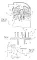
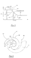
- Scroll compressor 20 includes an orbiting scroll member 22 driven by a shaft 24.
- a fixed scroll member 26 has a helical scroll wrap 28 extending from a base plate and interfitting with a helical scroll wrap 27 extending from a base plate of orbiting scroll member 22.
- a discharge port 23 receives the compressed fluid.
- a back pressure chamber 29 is defined by a pair of seals 30 and 32 and a crank case 33.
- a vent hole 34 taps fluid from pressure chambers defined between the scroll wraps 27 and 28 to the back pressure chamber 29.
- the fluid tapped to back pressure chamber 29 is utilized to counteract a separating force created near the center axis of the orbiting scroll member 22 which tends to axially separate the orbiting and fixed scroll members 22 and 26.
- the force developed in the back pressure chamber 29 opposes this separating force, and maintains the orbiting scroll member 22 biased toward the fixed scroll member 26.
- vent hole 34 is generally open to the pressure chambers defined between the scroll wraps 27 and 28 through the majority of the orbiting cycle of the orbiting scroll wrap 22.
- vent hole 34 communicates varying and pulsating pressures to back pressure chamber 29.
- the pressure developed between the scroll wraps 27 and 28 varies during the operating cycle.
- the pressure increases from a low or suction pressure 41 to a high or discharge pressure 42.
- An intermediate pressure ramp 43 extends from the suction pressure 41 to the high pressure 42.
- the prior art vent hole 34 is typically exposed to intermediate pressure along a portion of ramp 43 and a portion of the high pressure 42. This period of exposure is illustrated by envelope region 47.
- the fixed scroll wrap 28 passes over hole 34 closing it momentarily. This closure is typically incidental and for a limited time.
- the pressure in the back pressure chamber 29 pulsates and may vary dramatically. This becomes particularly acute in high pressure ratio scroll compressor applications.
- Pulsation in the back pressure chamber has been found to result in back pressure chamber seal failure, and unstable operation.
- the pulsation results in a varying back pressure force to oppose the separating force between the orbiting and fixed scroll members.
- the varying force may not always successfully resist the separating force, particularly when the back chamber pressure is at a low point of the pulsation.
- a valve may be placed on the discharge port 23.
- the valve is selectively opened and closed in response to a discharge pressure 44 that is increased dramatically above an uppermost point 45 of the intermediate pressure ramp 43. When this occurs, pressures along the intermediate pressure ramp that are closer to the lower pressure range become particularly undesirable for use in back pressure chamber 29.
- point 45 may actually be higher than the discharge pressure 46. In these applications, eliminating the intermediate pressure altogether would be undesirable, as there are portions near the point 45 which are actually the highest operational pressures for the particular compressor application.
- the present invention overcomes the challenges in the prior art by developing a scroll compressor wherein the vent hole is only uncovered for a small portion of the operational cycle of the scroll compressor.
- the vent hole is effectively closed over the majority of the operational cycle of the scroll compressor.
- a designer can ensure the vent hole is exposed to an optimum selection of intermediate and discharge pressures, which is communicated to, and maintained in, the back pressure chamber. Pressure pulsations are also reduced.
- the pumping losses found in the prior art are also reduced dramatically.
- the tapping or venting system is configured such that it selectively vents the fluid to the back pressure chamber from the pressure chambers at an intermediate pressure over a small portion of the cycle, and then vents the fluid at the discharge pressure over a separate small portion of the cycle.
- the vent hole is preferably closed between the tapping of the intermediate pressure portion and the discharge pressure portion.
- the vent hole extends through the tip of the scroll wrap of the orbiting scroll.
- the hole is closed or abuts an end face of the base of the fixed scroll for the majority of its operational cycle. However, for a relatively small portion of its cycle it is exposed to an intermediate pressure. It is then again closed for a period of time, and then exposed to a discharge pressure for a small portion of its cycle.
- grooves are formed in the base plate of the fixed scroll to tap the discharge and intermediate pressure to a location where they are periodically communicated to the vent hole in the orbiting scroll wrap as the orbiting scroll wrap moves relative to the fixed scroll wrap.
- vent holes are formed through the base plate of the orbiting or fixed scrolls.
- the scroll wrap of the other scroll member is positioned over the vent hole for the majority of the operational cycle of the scroll compressor.
- the vent hole is opened for a small portion of the cycle of the scroll compressor where it would be exposed to an intermediate pressure, and also for a small portion where it would be exposed to a discharge pressure.
- Figure 1A shows a prior art scroll compressor.
- Figure 1B is a graph showing the pressures encountered during a typical cycle of the prior art scroll compressor.
- Figure 2 shows an inventive orbiting scroll according to a first embodiment of the present invention.
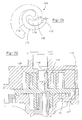
- Figure 3 shows a center portion of a fixed scroll utilized with the first embodiment of the present invention.
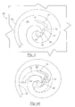
- Figure 4A shows a first step during the cycle of the first embodiment of the present invention.
- Figure 4B shows the step shown in Figure 4A with the orbiting scroll wrap removed for clarity.
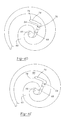
- Figure 4C shows a subsequent step.
- Figure 4D shows a subsequent step.
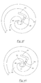
- Figure 4E shows a subsequent step.
- Figure 4F shows a subsequent step.
- Figure 4G shows a subsequent step.
- Figure 5 is a graph similar to Figure 1B, but showing the first embodiment of the present invention.
- Figure 6 shows a second embodiment of the present invention.
- Figure 7A shows a third embodiment of the present invention.
- FIG. 7B shows further detail of the third embodiment.
- An orbiting scroll 50 shown in Figure 2 incorporates a base plate 52 having a scroll wrap 53 extending from base plate 52.
- a vent hole 54 is formed through a tip 56 of the wrap 53. Vent hole 54 communicates with a bore 58 leading to a cross bore 60 extending through the base 52 to a tap hole 62. Hole 62 communicates with a back pressure chamber 29 as in the prior art.
- a plug 64 closes the bore 60 at an end of base 52.
- Figure 3 shows a center portion of the wrap of a fixed scroll member 60 which is preferably utilized with the orbiting scroll member 50.
- a wrap 62 extends from a base plate 64.
- the discharge port 66 is found generally at a center location on base plate 64.
- a first high pressure tap groove 68 extends from an end 70 which communicates with the discharge port 66 to a remote end 72.
- An intermediate pressure groove 74 extends from an end 76 positioned adjacent the end 72 of groove 68 to a remote end 78.
- the grooves 68 and 74 could be replaced by tap holes to tap the fluid to the locations of the groove ends on the base plate.
- the orbiting scroll wrap 53 and vent hole 54 are shown on top of the fixed scroll 60.
- the vent hole 54 is shown aligned with the base plate 64, and out of communication with both grooves 68 and 74.
- the close spacing between the wrap 53 and the base plate 64 will provide a high resistance to flow entering the vent hole 54.
- the fluid previously captured in the back pressure chamber 29 remains, and the pnor art pulsation and pumping losses are eliminated during this portion of the cycle.
- the groove 74 is shown communicating to an intermediate pressure radially outwardly of the wrap 53.
- Groove 68 constantly communicates to discharge pressure through the discharge port 66.
- Figure 4B shows an operational point similar to that shown in Figure 4A, but with the orbiting scroll wrap 53 removed for clarity.
- the vent hole 54 is shown at a position approximately equal to that shown in Figure 4A.
- Figure 4C shows a step slightly further along in the operational cycle of the scroll compressor of this embodiment.
- the tap hole 54 is still not communicating with either groove 68 or 74.
- FIG. 4D shows a point somewhat subsequent to that shown in Figure 4C.
- Vent hole 54 now communicates with the inner end 76 of the groove 74.
- An intermediate pressure fluid is now tapped from groove end 78 to portion 76, and then through the vent hole 54 to the back pressure chamber.
- End portion of the groove 74 is not covered by the orbiting scroll wrap at this point such that it can communicate an intermediate pressure to end 76.
- the location where the intermediate pressure is tapped to the portion 76 at this cyclical point can be controlled such that the particular intermediate pressure desired for the particular scroll compressor can be carefully selected. As an example, in some applications it may be desirable to have an intermediate pressure that is as high as possible tapped to vent hole 54.
- the shape of the groove 74 is designed such that when the vent hole 54 is in the location shown in Figure 4D, the intermediate pressure exposed to the groove 74 is from the highest intermediate pressure point.
- Figure 4E shows a step somewhat subsequent to that shown in Figure 4D. At this point, vent hole 54 is about to move out of communication with the groove 74 by moving beyond the end 76.
- vent hole 54 is now out of communication with both grooves 74 and 68. At this point, the vapor in the back pressure chamber 29 is captured and maintained. Again, pulsation and pumping losses are eliminated for this portion of the cycle.
- vent hole 54 is now in communication with the end 72 of the groove 68.
- discharge pressure from the discharge port 66 communicates from end 70 to end 72, through tap hole 54, and into back pressure chamber 29.
- the present invention allows a designer to carefully control the pressures in back pressure chamber 29.
- Figure 5 shows the pressure of a pressure chamber during one cycle of the present invention. As shown, the designer could carefully capture vapor at various pressures as desired for the particular scroll compressor in the two small envelope regions 77 and 78. Thus, the designer is able to capture vapor at a discharge pressure over envelope region 77 and also capture vapor over a small envelope region 78 at a desirable intermediate pressure.
- the force tending to separate the scrolls, and against which the back chamber force is intended to act is dependent in part on the intermediate pressure ramp 43 and is part on the discharge pressure 42 (or 44 or 46 as it may vary). It is thus desirable and necessary for the back chamber pressure and its resultant force to be dependent on and independently responsive to those two pressure components.
- Proper selection of the widths of envelope regions 77 and 78, which determine the amount of time the vent 54 is exposed to groove ends 72 and 76 respectively, as well as selection of the location of envelope region 78 on intermediate pressure ramps 43 and of the area of back chamber 29 all can result in tailoring of the back chamber pressure and its resulting force to optimally act against and respond to changes in the scroll separating force.
- a higher average pressure in envelope region 78 will result in a higher average pressure in the back chamber 29 with no loss in responsiveness to the magnitude of intermediate pressure ramp 43.
- the higher average pressure means that the back chamber area may be reduced for a given magnitude of back chamber force and thus the overall size of the compressor may be reduced.
- Figure 6 shows a second embodiment 90 wherein the orbiting scroll 91 has a base 92 with two pressure taps 94 and 96 formed adjacent a portion of its wrap 98.
- the holes 94 and 96 are preferably shown near the inner end of the wrap 98.
- the fixed scroll 97 is shown in this location covering the tap 94, but exposing the tap 96.
- the dotted lines 99 and 100 show the movement of the holes 94 and 96 during the orbiting movement of the orbiting scroll wrap 91.
- hole 94 and hole 96 will be covered by the scroll wrap 97.
- Hole 96 is in communication with discharge pressure for a small portion of the compression cycle corresponding to envelope region 77 and hole 94 is in communication with intermediate pressure for a small portion of the compression cycle corresponding to envelope 78. Both holes are also in communication with back chamber 29.
- Figure 7A shows another embodiment 109 of the present invention.
- the fixed scroll wrap 110 has a base 112 formed adjacent to wrap 114. Vent holes 116 and 118 are formed through the base 112.
- the orbiting scroll wrap 120 is shown covering hole 116, but exposing hole 118. During movement of the scroll wrap 120, again, holes 116 and 118 will be periodically exposed to pressure during selected portions of the compression cycle. However, as was the case in the prior embodiments, it is preferred that during the majority of the operational cycle of the scroll compressor of this embodiment, the orbiting scroll wrap 120 cover holes 116 and 118.
- Figure 7B shows further features of the third embodiment shown in Figure 7A.
- a fluid communication line 122 extends around and through the fixed scroll wrap 110 to the back pressure chamber 29.
- the present invention discloses a method and apparatus for controlling the fluid tapped or vented to the back pressure chamber of the scroll compressor.
- the tap occurs over two relatively small portions of the operational cycle of the scroll compressor. During a first portion, an intermediate pressure is tapped to the back pressure chamber. The tap is then closed for a period of the operational cycle of the scroll compressor. A tap is then exposed to a discharge pressure, and then again closed.
- the present invention taps fluid at two relatively small, and carefully selected portions of the operational cycle of the scroll compressor to the back pressure chamber. In this way, the operator may eliminate pulsations in the back pressure chamber, pumping losses through the vent holes, and also can carefully control the pressure found in the back pressure chamber.
- the grooves as shown in Figure 3 could be placed in the orbiting scroll.
- a vent hole could be placed in the fixed scroll with a passage arrangement such as shown in Figure 7.
- the grooves such as shown in the Figure 3 embodiment could be utilized with two vent holes through the tip of the orbiting scroll. Each vent hole could communicate with one of the grooves exclusively.
- back pressure chamber when the term "back pressure chamber" is utilized in this application it should be understood that by utilizing three seals one could achieve a pair of sub-chambers which are separated from each other. This type of "dual-chamber" back pressure chamber is still within the scope of this invention.
- back pressure chamber is utilized in this application it should be understood that by utilizing three seals one could achieve a pair of sub-chambers which are separated from each other. This type of "dual-chamber" back pressure chamber is still within the scope of this invention.
Landscapes
- Engineering & Computer Science (AREA)
- Mechanical Engineering (AREA)
- General Engineering & Computer Science (AREA)
- Rotary Pumps (AREA)
- Applications Or Details Of Rotary Compressors (AREA)
- Compressor (AREA)
Applications Claiming Priority (2)
| Application Number | Priority Date | Filing Date | Title |
|---|---|---|---|
| US08/789,933 US5762483A (en) | 1997-01-28 | 1997-01-28 | Scroll compressor with controlled fluid venting to back pressure chamber |
| US789933 | 1997-01-28 |
Publications (2)
| Publication Number | Publication Date |
|---|---|
| EP0855512A1 true EP0855512A1 (fr) | 1998-07-29 |
| EP0855512B1 EP0855512B1 (fr) | 2003-04-09 |
Family
ID=25149153
Family Applications (1)
| Application Number | Title | Priority Date | Filing Date |
|---|---|---|---|
| EP98300043A Expired - Lifetime EP0855512B1 (fr) | 1997-01-28 | 1998-01-06 | Compresseur à spirales avec échappement de fluide contrôlé vers une chambre arrière d'étanchéité |
Country Status (12)
| Country | Link |
|---|---|
| US (2) | US5762483A (fr) |
| EP (1) | EP0855512B1 (fr) |
| JP (1) | JP2912322B2 (fr) |
| KR (1) | KR100298605B1 (fr) |
| CN (1) | CN1092292C (fr) |
| BR (1) | BR9800457A (fr) |
| DE (1) | DE69813054T2 (fr) |
| EG (1) | EG21440A (fr) |
| ES (1) | ES2191252T3 (fr) |
| MY (1) | MY115572A (fr) |
| SA (1) | SA98180824B1 (fr) |
| TW (1) | TW347443B (fr) |
Families Citing this family (33)
| Publication number | Priority date | Publication date | Assignee | Title |
|---|---|---|---|---|
| JP3874469B2 (ja) * | 1996-10-04 | 2007-01-31 | 株式会社日立製作所 | スクロール圧縮機 |
| US6206652B1 (en) | 1998-08-25 | 2001-03-27 | Copeland Corporation | Compressor capacity modulation |
| US6146118A (en) * | 1998-06-22 | 2000-11-14 | Tecumseh Products Company | Oldham coupling for a scroll compressor |
| JP2000220585A (ja) * | 1999-01-28 | 2000-08-08 | Toyota Autom Loom Works Ltd | スクロール型圧縮機 |
| KR100576631B1 (ko) * | 1999-12-21 | 2006-05-04 | 한라공조주식회사 | 맥동압 저감구조를 가지는 압축기 |
| JP4599764B2 (ja) * | 2001-06-08 | 2010-12-15 | ダイキン工業株式会社 | スクロール型流体機械及び冷凍装置 |
| US6527528B1 (en) * | 2001-10-15 | 2003-03-04 | Scroll Technologies | Scroll compressor with controlled fluid venting |
| JP4519489B2 (ja) * | 2004-03-15 | 2010-08-04 | 日立アプライアンス株式会社 | スクロール圧縮機 |
| US7338264B2 (en) * | 2005-05-31 | 2008-03-04 | Scroll Technologies | Recesses for pressure equalization in a scroll compressor |
| JP4355308B2 (ja) * | 2005-09-01 | 2009-10-28 | 日立アプライアンス株式会社 | スクロール流体機械 |
| JP2007138868A (ja) * | 2005-11-21 | 2007-06-07 | Hitachi Appliances Inc | スクロール圧縮機 |
| US8157538B2 (en) | 2007-07-23 | 2012-04-17 | Emerson Climate Technologies, Inc. | Capacity modulation system for compressor and method |
| US7997883B2 (en) * | 2007-10-12 | 2011-08-16 | Emerson Climate Technologies, Inc. | Scroll compressor with scroll deflection compensation |
| JP4518206B2 (ja) * | 2007-12-28 | 2010-08-04 | ダイキン工業株式会社 | シングルスクリュー圧縮機 |
| KR101442547B1 (ko) * | 2008-08-05 | 2014-09-23 | 엘지전자 주식회사 | 스크롤 압축기 |
| WO2010036614A2 (fr) * | 2008-09-26 | 2010-04-01 | Carrier Corporation | Commande de décharge de compresseur sur un système de réfrigération de transport |
| JP5201113B2 (ja) | 2008-12-03 | 2013-06-05 | 株式会社豊田自動織機 | スクロール型圧縮機 |
| BRPI1007407A2 (pt) | 2009-01-27 | 2016-02-16 | Emerson Climate Technologies | sistema e método de descarregamento para um compressor |
| KR101576459B1 (ko) * | 2009-02-25 | 2015-12-10 | 엘지전자 주식회사 | 스크롤 압축기 및 이를 적용한 냉동기기 |
| JP4614009B1 (ja) * | 2009-09-02 | 2011-01-19 | ダイキン工業株式会社 | スクロール圧縮機 |
| US8579614B2 (en) * | 2011-02-04 | 2013-11-12 | Danfoss Scroll Technologies Llc | Scroll compressor with three discharge valves, and discharge pressure tap to back pressure chamber |
| CN103452840A (zh) * | 2013-09-12 | 2013-12-18 | 安徽奥特佳科技发展有限公司 | 双级压缩中间喷射的汽车热泵电动涡旋压缩机 |
| WO2015085823A1 (fr) * | 2013-12-12 | 2015-06-18 | 艾默生环境优化技术(苏州)有限公司 | Compresseur à spirales |
| CN104712556B (zh) * | 2013-12-12 | 2019-06-25 | 艾默生环境优化技术(苏州)有限公司 | 涡旋压缩机 |
| DE102015120151A1 (de) | 2015-11-20 | 2017-05-24 | OET GmbH | Verdrängermaschine nach dem Spiralprinzip, Verfahren zum Betreiben einer Verdrängermaschine, Fahrzeugklimaanlage und Fahrzeug |
| JP6274280B1 (ja) * | 2016-08-31 | 2018-02-07 | ダイキン工業株式会社 | スクロール圧縮機 |
| DE102017110913B3 (de) * | 2017-05-19 | 2018-08-23 | OET GmbH | Verdrängermaschine nach dem Spiralprinzip, Verfahren zum Betreiben einer Verdrängermaschine, Fahrzeugklimaanlage und Fahrzeug |
| KR102031851B1 (ko) * | 2018-04-13 | 2019-10-14 | 엘지전자 주식회사 | 전동식 압축기 |
| US11078907B2 (en) * | 2018-11-08 | 2021-08-03 | Beijing University Of Chemical Technology | Scroll type micro-compressor, and method for machining fixed scroll plate and orbit scroll plate thereof |
| JP7349279B2 (ja) * | 2019-07-12 | 2023-09-22 | サンデン株式会社 | スクロール圧縮機 |
| US11761446B2 (en) | 2021-09-30 | 2023-09-19 | Trane International Inc. | Scroll compressor with engineered shared communication port |
| US12292048B2 (en) * | 2022-09-13 | 2025-05-06 | Mahle International Gmbh | Electric compressor with scroll bearing injection orifice |
| CN118815715B (zh) * | 2024-08-02 | 2026-01-30 | 珠海格力节能环保制冷技术研究中心有限公司 | 涡旋压缩机、空调器 |
Citations (3)
| Publication number | Priority date | Publication date | Assignee | Title |
|---|---|---|---|---|
| US4993928A (en) * | 1989-10-10 | 1991-02-19 | Carrier Corporation | Scroll compressor with dual pocket axial compliance |
| US5277563A (en) * | 1992-08-10 | 1994-01-11 | Industrial Technology Research Institute | Scroll compressor with axial sealing apparatus |
| WO1996020345A1 (fr) * | 1994-12-23 | 1996-07-04 | Bristol Compressors, Inc. | Compresseur a spirales comportant une structure de palier dans une spirale a deplacement orbital afin d'eliminer les forces de basculement |
Family Cites Families (11)
| Publication number | Priority date | Publication date | Assignee | Title |
|---|---|---|---|---|
| US3924977A (en) * | 1973-06-11 | 1975-12-09 | Little Inc A | Positive fluid displacement apparatus |
| JPS55107093A (en) * | 1979-02-13 | 1980-08-16 | Hitachi Ltd | Enclosed type scroll compressor |
| JPS55160193A (en) * | 1979-05-28 | 1980-12-12 | Hitachi Ltd | Scroll fluid equipment |
| JPS6073080A (ja) * | 1983-09-30 | 1985-04-25 | Toshiba Corp | スクロ−ル型圧縮装置 |
| GB2162899B (en) * | 1984-06-27 | 1988-06-15 | Toshiba Kk | Scroll compressors |
| JPS6153486A (ja) * | 1984-08-22 | 1986-03-17 | Hitachi Ltd | スクロ−ル圧縮機 |
| JPH02118362A (ja) * | 1988-10-26 | 1990-05-02 | Hitachi Ltd | 容量制御空調機 |
| US4992032A (en) * | 1989-10-06 | 1991-02-12 | Carrier Corporation | Scroll compressor with dual pocket axial compliance |
| JP2782858B2 (ja) * | 1989-10-31 | 1998-08-06 | 松下電器産業株式会社 | スクロール気体圧縮機 |
| US5090878A (en) * | 1991-01-14 | 1992-02-25 | Carrier Corporation | Non-circular orbiting scroll for optimizing axial compliancy |
| JPH051677A (ja) * | 1991-06-27 | 1993-01-08 | Hitachi Ltd | スクロール圧縮機 |
-
1997
- 1997-01-28 US US08/789,933 patent/US5762483A/en not_active Expired - Fee Related
- 1997-12-31 CN CN97126245A patent/CN1092292C/zh not_active Expired - Fee Related
-
1998
- 1998-01-06 DE DE69813054T patent/DE69813054T2/de not_active Expired - Lifetime
- 1998-01-06 ES ES98300043T patent/ES2191252T3/es not_active Expired - Lifetime
- 1998-01-06 EP EP98300043A patent/EP0855512B1/fr not_active Expired - Lifetime
- 1998-01-07 MY MYPI98000071A patent/MY115572A/en unknown
- 1998-01-26 EG EG9398A patent/EG21440A/xx active
- 1998-01-26 TW TW087101109A patent/TW347443B/zh not_active IP Right Cessation
- 1998-01-26 BR BR9800457A patent/BR9800457A/pt not_active IP Right Cessation
- 1998-01-26 KR KR1019980002452A patent/KR100298605B1/ko not_active Expired - Fee Related
- 1998-01-28 JP JP10015176A patent/JP2912322B2/ja not_active Expired - Fee Related
- 1998-02-10 SA SA98180824A patent/SA98180824B1/ar unknown
- 1998-02-27 US US09/032,554 patent/US6517332B1/en not_active Expired - Lifetime
Patent Citations (3)
| Publication number | Priority date | Publication date | Assignee | Title |
|---|---|---|---|---|
| US4993928A (en) * | 1989-10-10 | 1991-02-19 | Carrier Corporation | Scroll compressor with dual pocket axial compliance |
| US5277563A (en) * | 1992-08-10 | 1994-01-11 | Industrial Technology Research Institute | Scroll compressor with axial sealing apparatus |
| WO1996020345A1 (fr) * | 1994-12-23 | 1996-07-04 | Bristol Compressors, Inc. | Compresseur a spirales comportant une structure de palier dans une spirale a deplacement orbital afin d'eliminer les forces de basculement |
Also Published As
| Publication number | Publication date |
|---|---|
| KR19980070887A (ko) | 1998-10-26 |
| JPH10213083A (ja) | 1998-08-11 |
| JP2912322B2 (ja) | 1999-06-28 |
| EG21440A (en) | 2001-10-31 |
| CN1092292C (zh) | 2002-10-09 |
| TW347443B (en) | 1998-12-11 |
| CN1189582A (zh) | 1998-08-05 |
| MY115572A (en) | 2003-07-31 |
| KR100298605B1 (ko) | 2002-01-15 |
| DE69813054D1 (de) | 2003-05-15 |
| ES2191252T3 (es) | 2003-09-01 |
| BR9800457A (pt) | 1999-06-01 |
| EP0855512B1 (fr) | 2003-04-09 |
| DE69813054T2 (de) | 2004-02-12 |
| US5762483A (en) | 1998-06-09 |
| SA98180824B1 (ar) | 2006-10-11 |
| US6517332B1 (en) | 2003-02-11 |
Similar Documents
| Publication | Publication Date | Title |
|---|---|---|
| US5762483A (en) | Scroll compressor with controlled fluid venting to back pressure chamber | |
| KR101253135B1 (ko) | 피스톤 조립체를 가지고 있는 압축기 | |
| AU768192B2 (en) | Compressor pulse width modulation | |
| US6176686B1 (en) | Scroll machine with capacity modulation | |
| US5855475A (en) | Scroll compressor having bypass valves | |
| KR100291408B1 (ko) | 용량 조절식 스크롤 머신 | |
| US20190186491A1 (en) | Variable Volume Ratio Compressor | |
| EP1498610A2 (fr) | Compresseur à spirales à capacité modulée | |
| EP2055957B1 (fr) | Compresseur à spirales | |
| US20070036661A1 (en) | Capacity modulated scroll compressor | |
| EP1160453B1 (fr) | Compresseur a volutes | |
| AU3577899A (en) | Stepped annular intermediate pressure chamber for axial compliance in a scroll compressor | |
| KR20090014091A (ko) | 단계식 용량 조절을 가진 계단식 스크롤 압축기 | |
| US6190138B1 (en) | Flow valve for correcting reverse rotation in scroll compressor | |
| US5562435A (en) | Structure for preventing axial leakage in a scroll compressor | |
| US6554592B1 (en) | Scroll compressor with condition responsive back pressure chamber valve | |
| US6527528B1 (en) | Scroll compressor with controlled fluid venting | |
| US6116867A (en) | Scroll machine with capacity modulation | |
| US6203299B1 (en) | Capacity modulation for scroll compressors | |
| US6464470B1 (en) | Scroll compressor with variable discharge port | |
| JP2006009640A (ja) | スクロール圧縮機 | |
| US5350280A (en) | Fluid compressor | |
| AU2003252946B2 (en) | Compressor pulse width modulation | |
| JP2001032787A (ja) | 可変容量スクロール型圧縮機 |
Legal Events
| Date | Code | Title | Description |
|---|---|---|---|
| PUAI | Public reference made under article 153(3) epc to a published international application that has entered the european phase |
Free format text: ORIGINAL CODE: 0009012 |
|
| 17P | Request for examination filed |
Effective date: 19980129 |
|
| AK | Designated contracting states |
Kind code of ref document: A1 Designated state(s): BE DE ES FR IT |
|
| AX | Request for extension of the european patent |
Free format text: AL;LT;LV;MK;RO;SI |
|
| AKX | Designation fees paid |
Free format text: BE DE ES FR IT |
|
| RBV | Designated contracting states (corrected) |
Designated state(s): BE DE ES FR IT |
|
| 17Q | First examination report despatched |
Effective date: 20010724 |
|
| GRAH | Despatch of communication of intention to grant a patent |
Free format text: ORIGINAL CODE: EPIDOS IGRA |
|
| GRAH | Despatch of communication of intention to grant a patent |
Free format text: ORIGINAL CODE: EPIDOS IGRA |
|
| GRAA | (expected) grant |
Free format text: ORIGINAL CODE: 0009210 |
|
| AK | Designated contracting states |
Designated state(s): BE DE ES FR IT |
|
| REG | Reference to a national code |
Ref country code: ES Ref legal event code: FG2A Ref document number: 2191252 Country of ref document: ES Kind code of ref document: T3 |
|
| ET | Fr: translation filed | ||
| PLBE | No opposition filed within time limit |
Free format text: ORIGINAL CODE: 0009261 |
|
| STAA | Information on the status of an ep patent application or granted ep patent |
Free format text: STATUS: NO OPPOSITION FILED WITHIN TIME LIMIT |
|
| 26N | No opposition filed |
Effective date: 20040112 |
|
| PGFP | Annual fee paid to national office [announced via postgrant information from national office to epo] |
Ref country code: ES Payment date: 20100128 Year of fee payment: 13 |
|
| PGFP | Annual fee paid to national office [announced via postgrant information from national office to epo] |
Ref country code: IT Payment date: 20100115 Year of fee payment: 13 Ref country code: FR Payment date: 20100208 Year of fee payment: 13 |
|
| PGFP | Annual fee paid to national office [announced via postgrant information from national office to epo] |
Ref country code: DE Payment date: 20100107 Year of fee payment: 13 Ref country code: BE Payment date: 20100125 Year of fee payment: 13 |
|
| BERE | Be: lapsed |
Owner name: *CARRIER CORP. Effective date: 20110131 |
|
| REG | Reference to a national code |
Ref country code: FR Ref legal event code: ST Effective date: 20110930 |
|
| PG25 | Lapsed in a contracting state [announced via postgrant information from national office to epo] |
Ref country code: FR Free format text: LAPSE BECAUSE OF NON-PAYMENT OF DUE FEES Effective date: 20110131 |
|
| PG25 | Lapsed in a contracting state [announced via postgrant information from national office to epo] |
Ref country code: BE Free format text: LAPSE BECAUSE OF NON-PAYMENT OF DUE FEES Effective date: 20110131 |
|
| REG | Reference to a national code |
Ref country code: DE Ref legal event code: R119 Ref document number: 69813054 Country of ref document: DE Effective date: 20110802 |
|
| PG25 | Lapsed in a contracting state [announced via postgrant information from national office to epo] |
Ref country code: IT Free format text: LAPSE BECAUSE OF NON-PAYMENT OF DUE FEES Effective date: 20110106 |
|
| REG | Reference to a national code |
Ref country code: ES Ref legal event code: FD2A Effective date: 20120220 |
|
| PG25 | Lapsed in a contracting state [announced via postgrant information from national office to epo] |
Ref country code: ES Free format text: LAPSE BECAUSE OF NON-PAYMENT OF DUE FEES Effective date: 20110107 |
|
| PG25 | Lapsed in a contracting state [announced via postgrant information from national office to epo] |
Ref country code: DE Free format text: LAPSE BECAUSE OF NON-PAYMENT OF DUE FEES Effective date: 20110802 |