EP0855560A2 - Dispositif de ventilation - Google Patents
Dispositif de ventilation Download PDFInfo
- Publication number
- EP0855560A2 EP0855560A2 EP97112976A EP97112976A EP0855560A2 EP 0855560 A2 EP0855560 A2 EP 0855560A2 EP 97112976 A EP97112976 A EP 97112976A EP 97112976 A EP97112976 A EP 97112976A EP 0855560 A2 EP0855560 A2 EP 0855560A2
- Authority
- EP
- European Patent Office
- Prior art keywords
- ventilation
- filter elements
- housing
- filter element
- ventilation device
- Prior art date
- Legal status (The legal status is an assumption and is not a legal conclusion. Google has not performed a legal analysis and makes no representation as to the accuracy of the status listed.)
- Granted
Links
- 238000009423 ventilation Methods 0.000 title claims description 116
- 238000011084 recovery Methods 0.000 claims abstract description 32
- 239000000853 adhesive Substances 0.000 claims description 5
- 230000001070 adhesive effect Effects 0.000 claims description 5
- 239000003570 air Substances 0.000 abstract 3
- 239000012080 ambient air Substances 0.000 abstract 1
- 230000003134 recirculating effect Effects 0.000 abstract 1
- 238000005192 partition Methods 0.000 description 14
- 238000005273 aeration Methods 0.000 description 9
- 239000000463 material Substances 0.000 description 8
- 238000013022 venting Methods 0.000 description 6
- 238000012423 maintenance Methods 0.000 description 5
- 238000007789 sealing Methods 0.000 description 5
- 241000446313 Lamella Species 0.000 description 4
- 239000011358 absorbing material Substances 0.000 description 4
- 238000004140 cleaning Methods 0.000 description 2
- 238000013016 damping Methods 0.000 description 2
- 238000009434 installation Methods 0.000 description 2
- 239000012774 insulation material Substances 0.000 description 2
- 238000004519 manufacturing process Methods 0.000 description 2
- 229910052751 metal Inorganic materials 0.000 description 2
- 239000002184 metal Substances 0.000 description 2
- 239000002245 particle Substances 0.000 description 2
- 238000011144 upstream manufacturing Methods 0.000 description 2
- RYGMFSIKBFXOCR-UHFFFAOYSA-N Copper Chemical compound [Cu] RYGMFSIKBFXOCR-UHFFFAOYSA-N 0.000 description 1
- 238000010521 absorption reaction Methods 0.000 description 1
- 229910052782 aluminium Inorganic materials 0.000 description 1
- XAGFODPZIPBFFR-UHFFFAOYSA-N aluminium Chemical compound [Al] XAGFODPZIPBFFR-UHFFFAOYSA-N 0.000 description 1
- 230000005540 biological transmission Effects 0.000 description 1
- 230000015572 biosynthetic process Effects 0.000 description 1
- 239000004020 conductor Substances 0.000 description 1
- 238000011109 contamination Methods 0.000 description 1
- 229910052802 copper Inorganic materials 0.000 description 1
- 239000010949 copper Substances 0.000 description 1
- 230000008878 coupling Effects 0.000 description 1
- 238000010168 coupling process Methods 0.000 description 1
- 238000005859 coupling reaction Methods 0.000 description 1
- 230000008021 deposition Effects 0.000 description 1
- 238000005553 drilling Methods 0.000 description 1
- 230000002349 favourable effect Effects 0.000 description 1
- 238000007667 floating Methods 0.000 description 1
- 239000006260 foam Substances 0.000 description 1
- 229920001821 foam rubber Polymers 0.000 description 1
- 238000010438 heat treatment Methods 0.000 description 1
- 238000002347 injection Methods 0.000 description 1
- 239000007924 injection Substances 0.000 description 1
- 238000009413 insulation Methods 0.000 description 1
- 238000000465 moulding Methods 0.000 description 1
- 230000000149 penetrating effect Effects 0.000 description 1
- 230000002093 peripheral effect Effects 0.000 description 1
- 238000000926 separation method Methods 0.000 description 1
- 239000007787 solid Substances 0.000 description 1
- 239000000243 solution Substances 0.000 description 1
Images


Classifications
-
- F—MECHANICAL ENGINEERING; LIGHTING; HEATING; WEAPONS; BLASTING
- F24—HEATING; RANGES; VENTILATING
- F24F—AIR-CONDITIONING; AIR-HUMIDIFICATION; VENTILATION; USE OF AIR CURRENTS FOR SCREENING
- F24F13/00—Details common to, or for air-conditioning, air-humidification, ventilation or use of air currents for screening
- F24F13/28—Arrangement or mounting of filters
-
- F—MECHANICAL ENGINEERING; LIGHTING; HEATING; WEAPONS; BLASTING
- F24—HEATING; RANGES; VENTILATING
- F24F—AIR-CONDITIONING; AIR-HUMIDIFICATION; VENTILATION; USE OF AIR CURRENTS FOR SCREENING
- F24F8/00—Treatment, e.g. purification, of air supplied to human living or working spaces otherwise than by heating, cooling, humidifying or drying
- F24F8/10—Treatment, e.g. purification, of air supplied to human living or working spaces otherwise than by heating, cooling, humidifying or drying by separation, e.g. by filtering
- F24F8/108—Treatment, e.g. purification, of air supplied to human living or working spaces otherwise than by heating, cooling, humidifying or drying by separation, e.g. by filtering using dry filter elements
-
- F—MECHANICAL ENGINEERING; LIGHTING; HEATING; WEAPONS; BLASTING
- F24—HEATING; RANGES; VENTILATING
- F24F—AIR-CONDITIONING; AIR-HUMIDIFICATION; VENTILATION; USE OF AIR CURRENTS FOR SCREENING
- F24F12/00—Use of energy recovery systems in air conditioning, ventilation or screening
- F24F12/001—Use of energy recovery systems in air conditioning, ventilation or screening with heat-exchange between supplied and exhausted air
- F24F12/006—Use of energy recovery systems in air conditioning, ventilation or screening with heat-exchange between supplied and exhausted air using an air-to-air heat exchanger
-
- F—MECHANICAL ENGINEERING; LIGHTING; HEATING; WEAPONS; BLASTING
- F24—HEATING; RANGES; VENTILATING
- F24F—AIR-CONDITIONING; AIR-HUMIDIFICATION; VENTILATION; USE OF AIR CURRENTS FOR SCREENING
- F24F8/00—Treatment, e.g. purification, of air supplied to human living or working spaces otherwise than by heating, cooling, humidifying or drying
- F24F8/10—Treatment, e.g. purification, of air supplied to human living or working spaces otherwise than by heating, cooling, humidifying or drying by separation, e.g. by filtering
-
- F—MECHANICAL ENGINEERING; LIGHTING; HEATING; WEAPONS; BLASTING
- F24—HEATING; RANGES; VENTILATING
- F24F—AIR-CONDITIONING; AIR-HUMIDIFICATION; VENTILATION; USE OF AIR CURRENTS FOR SCREENING
- F24F12/00—Use of energy recovery systems in air conditioning, ventilation or screening
- F24F12/001—Use of energy recovery systems in air conditioning, ventilation or screening with heat-exchange between supplied and exhausted air
- F24F2012/007—Use of energy recovery systems in air conditioning, ventilation or screening with heat-exchange between supplied and exhausted air using a by-pass for bypassing the heat-exchanger
-
- Y—GENERAL TAGGING OF NEW TECHNOLOGICAL DEVELOPMENTS; GENERAL TAGGING OF CROSS-SECTIONAL TECHNOLOGIES SPANNING OVER SEVERAL SECTIONS OF THE IPC; TECHNICAL SUBJECTS COVERED BY FORMER USPC CROSS-REFERENCE ART COLLECTIONS [XRACs] AND DIGESTS
- Y02—TECHNOLOGIES OR APPLICATIONS FOR MITIGATION OR ADAPTATION AGAINST CLIMATE CHANGE
- Y02B—CLIMATE CHANGE MITIGATION TECHNOLOGIES RELATED TO BUILDINGS, e.g. HOUSING, HOUSE APPLIANCES OR RELATED END-USER APPLICATIONS
- Y02B30/00—Energy efficient heating, ventilation or air conditioning [HVAC]
- Y02B30/56—Heat recovery units
Definitions
- the invention relates to a ventilation device for simultaneous ventilation of rooms and / or for short-circuit operation for air circulation in rooms, especially with a device for heat recovery from the ventilation media flow, with a housing, which is arranged on or in a building wall, for example on the inside of the room, and can be connected to a ventilation duct leading to the outside air for the ventilation and ventilation media flow, wherein two separate flow paths are formed within the housing, and filter elements are provided in both flow paths.
- Ventilation devices of this type are already known made by DE 38 28 011 C2.
- This ventilation device has a plate-shaped Filter element on, which between the exhaust air opening, the Front wall and the passage in the wall of the air duct structure is provided.
- the filter element consists of a flexible Filter material, for example a filter fleece, which is made in one piece.
- a front wall closing the housing is removed and the filter element along - partially arcuate curved - front edges of attached to the housing Cross bars inserted into a chamber.
- Filter element includes a forced ventilation fan U-shaped.
- part of the filter element has no filter function since it is neither in the ventilation nor is in the ventilation media flow of the ventilation device and that the filter element also contrary to its intended Flow direction can be installed if the used filter material in a designated direction having. Installation or maintenance of the ventilation device is due to the arrangement of the filter element complicates that the flexible filter element in the area cannot be seen behind the forced ventilation device can, so that unwanted folds or the like arise can.
- vent and Ventilation media flow different filter elements too use.
- the invention is based on the object, a To provide ventilation device of the type mentioned in the introduction, in which the filter element or elements as possible is or are designed to be easy to maintain. At the same time the optimal function of the filter element can be guaranteed.
- a preferred embodiment provides that the through the filter elements formed an L-shaped assembly Has cross section, through a filter element formed legs at least almost perpendicular to each other stand.
- Filter element with the larger thickness dimension on its Narrow side assigned to a broad side of the filter element which has the smaller thickness dimension is provided.
- the sensible and energy-saving operation of the Ventilation device is guaranteed when to separate the Media flows the area connection between the two Filter elements are sealed and thereby short circuits the Media flows can be prevented.
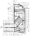
- Fig. 1 of the drawing shows a vertical section through a Ventilation device 1 for simultaneous ventilation of a room 2.
- This ventilation device 1 can be preferably inside the room, on or in a building wall 3 fasten, which has an opening 4 to the outside, in which can be used a tubular ventilation duct 5.
- the tubular ventilation duct 5 has a partition 6, the two longitudinal flow channels 7 and 8 of about same cross-section. Prefers the ventilation duct 5 has a round cross section in which through the partition 6 the two flow channels 7 and 8 are each provided with a semicircular cross section.
- the housing 9 of the ventilation device 1 has a trough-like base body 10 to a pipe section 11 firm, but preferably limited angular movement, is flanged, which is inserted into the opening 4 can be.
- the pipe section 11 tapers at least conical near its free end 12 on its outer circumference, while a diametrical partition 13 of the same in one conically opening groove 14 ends.
- a ventilation media flow path formed in this way 15 ends in a chamber 16 of the housing 9, which is provided with a larger flow cross-section, than the ventilation media flow path 15 itself Chamber 16 through a partition 17 in the aeration media flow path 15 and a vent media flow path 18 divided. The latter is through the pipe section 11 and the ventilation duct 5 in the opening 4 of the building wall 3 Outside air.
- the chamber 16 becomes the inside of the room limited by a front panel 19, which is essentially transverse to the central axis 5a of the ventilation duct 5 or Pipe section 11 extends.
- the front panel 19 is - like all other side walls of chamber 16 - with sound absorbing Material 20 lined.
- the front panel 19 does not consist of a levels, e.g. convex or concave curved, solid plate consists. In the embodiment, it has one - from the inside viewed from chamber 16 - curved outwards, that is concave shape. This means that any existing natural frequencies reduced and the noise reduction inside the chamber 16 favored.
- the partition 17 to the department of the ventilation media flow path 15 from Vent media flow path 18 in substantial parts of a device for heat recovery 25 is formed.
- a device for heat recovery 25 is preferably a recuperative Heat exchanger that has a cross-flow design. He consists of at least one stack of plates or plates 24, which consists of a larger number of individual lamellas or -Plates 23 is composed. Each of them can do one have approximately C-shaped cross section and, as in the 1, 4, 5 and 9 shows the embodiment shown, have an approximately square plan.
- the single lamella or -Plates 23 are formed as thin-walled as possible and are made of a good heat-conducting material, for example aluminum or copper.
- the individual lamellas or -Plates 23 are mutually normal to their plane directional axis rotated 90 ° against each other placed one on top of the other so that flow channels 21 between them and 22 are formed which alternate one around the other 90 ° twisted position so that through them air flows passed through in the layered position successive flow channels 21 and 22, respectively cross.
- the preferred and illustrated embodiment consists of thin-walled profile sections that like already described above, each offset by 90 ° to each other to be ordered. It is possible within the facility for heat recovery 25 or the one forming it Plate stack 24 each parallel to the media flow path 15, 18th running partition walls to provide the surface of the Enlarge device for heat recovery 25 and thus increase their efficiency. Through their directional function can but also the formation of a laminar flow favor.
- the heat recovery device 25 is in the aeration media flow path 15 upstream of a filter element 26, which the air introduced into room 2 from floating Free dirt particles.
- the device is also in the ventilation media flow path 18 Heat recovery 25 upstream a filter element 27, the just like the filter element 26, contamination of the Device for heat recovery 25 from room 2 vacuumed dirt particles prevented.
- the filter elements 26, 27 are both for the ventilation media flow 15 and for the ventilation media stream 18 in the intake path of Forced ventilation devices 28 and 29 respectively. Thereby is achieved that both in the filter elements 26 and 27th as well as in the device for heat recovery 25 a laminar flow is present, the full surface Flow guaranteed. This is supported by the 25 installed in the heat recovery device, (already mentioned) partitions or longitudinal webs, because these for a further alignment of the ventilation and the Ensure ventilation media flow (18).
- the forced ventilation devices 28, 29 are on the upper, horizontal boundary walls 42 and the Forced ventilation devices 29 are on the lower horizontal boundary walls 43 of the chamber 16 are arranged, so that there is the greatest possible distance to the Filter elements 26, 27 and to the device for Heat recovery 25 results. This also results in favorable flow conditions also a longer one Dwell time of the air flow with the associated better heating of the supplied ventilation media stream 15 through the entire housing 9.
- each of the Forced ventilation devices 28, 29 from pairs cooperating fans and that from the in the ventilation media flow 15 arranged fan pair 30, 31 and in Ventilation media stream 18 arranged fan pair 32, 33.
- blowers 30, 31 of the Ventilation media stream 15 arranged in the top of the housing 9 so that they have separate blowout channels 60, but one have common suction space 34.
- Vent media flow 18 and below in the housing 9 arranged blowers 32, 33 both a common Intake chamber 35 and a common blow-out duct 36 Blow-out duct 36 is ideally from pipe section 11 educated.
- the forced ventilation devices 28, 29 are each stored directly in a block-like insert body 37, for example made of foam plastic or foam rubber is formed. This will make the inevitable Internal noise of the blowers 30, 31 and 32, 33 to a minimum reduced or insulated because the fan vibrations do not increase the housing 9 are transmitted.
- Double blower or blower pairs 30/31 or 32/33 By designing as Double blower or blower pairs 30/31 or 32/33 is above also achieved that at the same volume flow, the blower 30, 31, 32, 33 can work at a relatively low speed. However, the volume flow generated with this is compared to one usually used twice as large Single blowers much larger.
- the forced ventilation devices 28, 29 can be in the housing 9 drawer-like - without additional fasteners - be stored. This is achieved through the creation of Open compartments 48, 49 inside the housing 9, in which the one-piece Allow forced ventilation devices 28, 29 to slide in.
- the power supply to the forced ventilation devices 28, 29 takes place, as will be described in more detail below, by attached to the rear wall of the housing 9 Contact points 46 with on the forced ventilation devices 28, 29 attached contact springs 47 cooperate. she will implemented wirelessly, so that the Forced ventilation devices 28, 29 effortlessly open Housing 9 can be removed.
- the arrangement of the Contact points 46 is in a manner known per se chosen so that the forced ventilation devices 28, 29 only in are properly supplied with power so that a possible incorrect assembly remains without consequences.
- the device for heat recovery 25 can Maintenance purposes can be removed from the housing 9. For this is first the pivotally mounted on the housing 9 Front plate 19 pivoted about a lower horizontal axis, so that the chamber 16 is open on the inside of the room.
- the Device for heat recovery 25 25 is together with the Filter elements 26 and 27 mounted on a frame 38, the is pivotable about a bearing axis 39.
- the bearing axis 39 is effective as a snap-snap connection, so that the frame 38 can be removed from the housing 9 in total.
- Of the Frame 38 has limits 40 which in the closed state the front panel 19 at corresponding sealing points 41 of the Bump housing 9 and the front panel 19.
- Filter elements 27, 26 can have different designs to have. So is the filter element 26, which in the aeration media flow 15 lies, with a higher degree of separation equipped as the filter element 27 for the ventilation media flow 18th
- the filter elements 26, 27 are detachable on the frame 38 attached, at least the filter element 26 for the Aeration media stream 15 from the device to Heat recovery 25 is spaced. This ensures that the entire filter element 26 is flowed through. At a Arrangement of the same directly on the device for Heat recovery 25 would, however, with their air-impermeable edge sections meet Filter sections entail a high pressure loss.
- the front plate 19 is curved in cross section to the outside executed and on the inside with insulation material 20 busy.
- the Housing 9 consists of a trough-like base body 10 which a frame 45 is releasably attached. All perpendicular to Main plane of the boundary walls of the Base body 10 are closed, so that if necessary Assembly of the ventilation device 1 also at least partially in one - indicated in FIG. 2 with dash-dotted lines - Niche 3a of the building wall 3 can take place.
- the frame 45 and the base body 10 are provided with seals 10a Flanges 10b connected and with - not shown - Fasteners, e.g. Screws, fastened together.
- the frame 45 When attaching the ventilation device 1 accordingly 2, the frame 45 is detached from the base body 10. Of the Base body 10 is fastened in the wall recess 3a and only then the frame 45 is flush with the wall surface Building wall 3 created. The frame 45 can then on Base body 10 are attached.
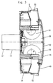
- Fig. 4 shows that provided within the housing 9 Course of the ventilation media flow path 15 using a Basic form of the ventilation device 1.
- the Aeration media stream 15 comes from - in this Representation not visible - flow channel 8 in breakthrough 4 of the building wall 3 by the also not shown Pipe section 11 and enters the chamber 16. From there it follows one with a multitude of redirections hatched arrows 15a marked path.
- Of the Aeration media stream 15 is initially in the chamber 16 from the ventilation media flow 18 through the partition 17 separated, after which it moves upwards through the Filter element 26 and the device for heat recovery 25 leads. From there it continues upwards to Suction side of the on the upper horizontal boundary wall 42nd the ventilation device 27 arranged in the chamber 16. In it, the two fans 30 and 31 Volume flow divided in half.
- a first half of the Volume flow is deflected to the left as shown and directed into a downward chute 50.
- the second half of the volumetric flow is added to this mirror-symmetric direction directed to the right, but what is not visible in Fig. 4.
- At the bottom of each shaft 50 are lateral outlet openings 51 through which the ventilation media flow 15 then gets into the interior of the room.
- the one on each side of the housing 9 and the outside of the chamber 16th along shaft 50 is with sound absorbing Material 20 lined with a liner to the Outer walls 52 to avoid the transfer of Structure-borne noise is generally sufficient.
- the shaft 50 is through Removing the frame 45 accessible from the base body 10.
- a second chamber 54 is formed approximately in the center of the housing 9.
- the Ventilation device 1 necessary electrical components as well the control and display instruments are also arranged, which are not shown.
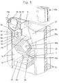
- Fig. 5 is provided within the housing 9
- Course of the ventilation media stream 18 also in one Principle of spatial form recognizable. He leads over Air inlet openings 55 at the top into the interior of the housing 9, as the open arrows 18a make clear.
- With two following right-angled bends 56, 57 he goes in a vertical shaft 58, which is behind the shaft 50 is arranged, so also along the outside of the chamber 16 guided.
- the shaft 58 cut in this illustration opens at the perpendicular boundary walls 59 through - not visible here - openings in the chamber 16 a.
- the filter element 27 to protect the in the vent media flow path 18 subsequently arranged device for Heat recovery 25 is from the rear wall of the housing 9 flows through to the front panel 19, the Ventilation media stream 18 in the suction chamber 35 below the Partition 17 arrives.
- the vent media flow path 18 leads from this - through the forced ventilation device 29 driven - in the flow channel 7 the Ventilation device 1 connects to the outside air.
- Fig. 5 shows by the arrows 18a that the Venting media stream 18 in several places - mostly right-angled - kinked.
- the Forced ventilation device 29 is arranged so that the Blow-out duct 36 of both fans 32 and 33 parallel to Central axis 5a of the ventilation duct 5, which is not visible here runs.
- FIGS. 4 and 5 show each only half of the aeration media flow 15 and the venting media stream 18, the second of which Half mirrored to the vertical central plane of the Ventilation unit 1 is guided.
- the forced ventilation devices 28, 29 both in the ventilation media flow 15 as well as in the venting media stream 18 Have an arrangement in which the suction path of the same - within of the housing 9 of the ventilation device 1 - each longer is dimensioned as the blow-out path. With this arrangement achieved that the operation of the Forced ventilation devices 28, 29 arise Internal noise of the blowers 30, 31 and 32, 33 a maximum Experience damping.
- the base body 10 and the frame 45 of the housing 9 are as Plastic injection molded parts, which is a dimensionally accurate and inexpensive production results.
- De-molding of the base body 10 is the wall 61 of the Shaft 58 or shaft 50 are designed loosely, i.e. the Wall 61 is only on the assembly of the frame 45 on the Base body 10 used. This also enables a Cleaning of those located in the venting media flow path 18 Flow channels that are not directly accessible.
- a preferred embodiment provides that the wall 61 a perfect fit, with soundproofing material on all sides enclosed and provided with a crease 62 Cardboard section exists. This can be in the event of any maintenance of the device simply removed from it and through a new section to be replaced.
- the Forced ventilation device 28 consists of an upper one and a lower housing half 65, 66.
- the - not shown - blower motors are on the bottom 68 of the upper housing half 65 attached.
- the blowers 32 and 33 suck in via the opening 66a and blow out to the side, the blow-out directions mirror-symmetrical to Transverse central axis 67 and away from each other.
- a guide 69 runs along the transverse central axis 67 through an open groove 70 in the upper housing half 65 and by a projection 71 on the lower housing half 66 is formed.
- this guide 69 shows a push rod 72 guided longitudinally, which cooperates at one end 73 with the front panel 19, while with the other end 74 on a push button switch 75 meets.
- the fixation of the lower housing half 66 on the upper Housing half 65 is carried out by the upper housing half 65 molded locking hooks 76, as shown in FIG. 8. This In the assembled state, latching hooks 76 engage in recesses 77 and lock a swivel bearing. This is through laterally open longitudinal eyelets 78 of the lower housing half 66 and in this engaging tab of the upper housing half 65 the is not shown here.
- the forced ventilation device 29 is equivalent to this Way equipped. However, it does not have the guide 69 and has the other blowout direction already described.
- Both forced ventilation devices 28 and 29 are like is highlighted several times, by at least one part Covering with soundproofing material to avoid Structure-borne noise transmissions.
- the profile sections 95, 96 are over that of the Profile bars 91, 92, 93 and the side cheeks 90 formed Frame 38 attached in that its side edges in Longitudinal grooves 91b, 92 and 93b of the profile bars 91, 92, 93 sit in. Additionally there are seals 91c, 92c and 93c appropriate.
- the profile bars 91, 92, 93 also have longitudinal grooves 91d, 92d, 93d seated seals 91e, 92e, 93e on the in a familiar way with those already ahead with reference to FIG. 1 sealing points 41 of the shown housing or front panel 19 cooperate.
- the side cheeks 90 are in the illustrated embodiment provided with a bore 97 to which a lateral Opening 98 connects.
- the center of the bore 97 forms a bearing axis 39 around which, as already described, the entire frame 38 is pivotally mounted.
- the bearing axis 39 in the housing 9 can be close to its end Sheathed flattened cylinder rod are formed, the has approximately the diameter 99 of the hole 97. In the field of Flattening corresponds to its cross section approximately the width 98a the opening 98, whereby a kind Bayonet lock arises, via which the frame 38 in the Housing 9 can be fixed immovably.
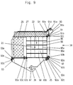
- Fig. 10 shows the frame 38 in the housing 9. Die Filter elements 26, 27, as already described, by the frame 38 worn, which also the device for Heat recovery 25 picks up.
- the filter elements 26, 27 are firmly connected and through an effective adhesive bond between them. This Adhesive connection works across the entire width of the Filter elements 26, 27 and causes the filter elements 26, 27 form a structural unit.
- This unit has an L-shaped cross section thereof Legs are formed by the filter elements 26, 27 that are at least almost perpendicular to each other. This will achieved that the filter elements 26, 27 after pivoting of the frame 38 together in one operation to the frame 38 can be removed.
- the L-shaped cross section of the Unit encompasses the device for Heat recovery 25 on two sides, being through the fixed Connection of the filter elements 26, 27 also a safe and spaced attachment of the filter element 26 relative to the Heat recovery device 25 is ensured.
- the filter element 26 consists of a pleated filter material by a surrounding frame 100 is enclosed.
- frame materials come e.g. Cardboard or metal in question.
- the filter element 27 consists of a filter mat formed by a fleece.
- the frame 100 supports or holds the filter element 26 on the one hand with its peripheral edges 100a, 100b between the longitudinal edges 93f of the profile bar 93. On the other hand, the frame 100 with one protruding beyond the plane of the filter element 26 Edge 100b against the heat recovery device 25 and the rear wall of the base body 10 is supported.
- connection of the filter elements can of course can also be designed to be detachable, the filter element 27 for example by means of an attached Velcro fastener is held on the filter element 26.
- Overlap area 103 makes sense that the filter element 26th with the larger thickness dimensions 101 on its narrow side 104 assigned to a broad side 105 of the filter element 27 which has the smaller thickness dimension 102. This maximizes the overlap area 103 and the Connection is expanded as much as possible. Also will achieved that consisting of the filter elements 26, 27 Unit receives a stable structure, the one has greater dimensional stability than the individual components.
- FIG. 10 in connection with FIG. 9, has the frame 38 in the operating state relative to the housing inclined installation position.
- the one at the top of the filter elements 26 and 27 located corner area 106 is with a chamfer 107 provided in the operating state of the ventilation device 1 runs parallel to the rear wall of the base body 10. Since the filter element 27 via this recessed chamfer 107 protrudes - as Fig. 9 shows - the material of the Filter element 27 in the installed state to the level of recessed chamfer 107 deforms and acts as a seal with the rear wall of the base body 9 together.
- the structural unit with the L-shaped cross section is 10, in the operating state of the Ventilation device 1 inclined so that the angle which of the leg of the L-shaped cross section is enclosed, is halved by the horizontal.
- the filter element 27 Forces equally on both filter elements 26, 27 and Frame 38 transmitted.
- the changing of the filter elements 26, 27 happens - how already described above - by pivoting the Frame 38 around the bearing axis 39 with the front panel 19 open whereby for cleaning purposes or for changing the by the Filter elements 26, 27 formed the entire unit Frame 38 removed from the housing 9 of the ventilation device 1 can be.
- the arrangement of the filter elements 26, 27 as a structural unit also causes an incorrect passage direction of the Media flows are counteracted by this.
- the different thickness dimensions 102, 103 of the Filter elements 26, 27 do not require that the filter elements 26, 27 different degrees of absorption or deposition exhibit.
Landscapes
- Engineering & Computer Science (AREA)
- Chemical & Material Sciences (AREA)
- Combustion & Propulsion (AREA)
- Mechanical Engineering (AREA)
- General Engineering & Computer Science (AREA)
- Ventilation (AREA)
- Filtering Of Dispersed Particles In Gases (AREA)
- Liquid Crystal (AREA)
- Seal Device For Vehicle (AREA)
- Duct Arrangements (AREA)
- Devices For Conveying Motion By Means Of Endless Flexible Members (AREA)
- Temperature-Responsive Valves (AREA)
- Valve-Gear Or Valve Arrangements (AREA)
- Cooling Or The Like Of Electrical Apparatus (AREA)
- Input Circuits Of Receivers And Coupling Of Receivers And Audio Equipment (AREA)
- Flow Control (AREA)
- Fluid-Driven Valves (AREA)
Applications Claiming Priority (2)
| Application Number | Priority Date | Filing Date | Title |
|---|---|---|---|
| DE29701324U DE29701324U1 (de) | 1997-01-24 | 1997-01-24 | Lüftungsvorrichtung |
| DE29701324U | 1997-01-24 |
Publications (3)
| Publication Number | Publication Date |
|---|---|
| EP0855560A2 true EP0855560A2 (fr) | 1998-07-29 |
| EP0855560A3 EP0855560A3 (fr) | 2002-01-02 |
| EP0855560B1 EP0855560B1 (fr) | 2004-04-21 |
Family
ID=8035087
Family Applications (1)
| Application Number | Title | Priority Date | Filing Date |
|---|---|---|---|
| EP97112976A Expired - Lifetime EP0855560B1 (fr) | 1997-01-24 | 1997-07-29 | Dispositif de ventilation |
Country Status (5)
| Country | Link |
|---|---|
| EP (1) | EP0855560B1 (fr) |
| AT (1) | ATE265030T1 (fr) |
| DE (2) | DE29701324U1 (fr) |
| NO (1) | NO973593L (fr) |
| PL (1) | PL323891A1 (fr) |
Cited By (3)
| Publication number | Priority date | Publication date | Assignee | Title |
|---|---|---|---|---|
| EP1296098A1 (fr) * | 2001-09-20 | 2003-03-26 | Kui Wong Yeung | Ventilateur avec échangeur de chaleur à haut rendement et filtre à air |
| DE20204755U1 (de) * | 2002-03-25 | 2003-05-28 | Meltem Wärmerückgewinnung GmbH & Co. KG, 82239 Alling | Luftaustauschvorrichtung |
| WO2022053247A1 (fr) * | 2020-09-11 | 2022-03-17 | Siegenia-Aubi Kg | Dispositif de ventilation |
Families Citing this family (3)
| Publication number | Priority date | Publication date | Assignee | Title |
|---|---|---|---|---|
| DE102014003753A1 (de) | 2014-03-18 | 2015-09-24 | Siegenia-Aubi Kg | Lüftungsvorrichtung |
| CN104654484B (zh) * | 2015-02-12 | 2017-05-10 | 梅立功 | 一种室内外空气流通净化集尘装置 |
| DE102016009790B3 (de) * | 2016-06-07 | 2017-12-07 | Seventilation Gmbh | Raumbe- und -entlüftungsgerät zur Montage in Durchbrüchen von Wänden oder Decken |
Citations (1)
| Publication number | Priority date | Publication date | Assignee | Title |
|---|---|---|---|---|
| DE3828011A1 (de) | 1988-05-30 | 1989-12-07 | Siegenia Frank Kg | Lueftungsvorrichtung zum gleichzeitigen be- und entlueften von raeumen |
Family Cites Families (3)
| Publication number | Priority date | Publication date | Assignee | Title |
|---|---|---|---|---|
| FR2529308B1 (fr) * | 1982-06-25 | 1987-06-05 | Godefroy Raymond | Groupe de ventilation pour des locaux |
| FR2533682A1 (fr) * | 1982-09-24 | 1984-03-30 | Fimec | Perfectionnements aux echangeurs de temperature a flux croises, notamment pour systemes de ventilation mecanique pour locaux |
| DE58905108D1 (de) * | 1988-05-30 | 1993-09-09 | Siegenia Frank Kg | Lueftungsvorrichtung zum gleichzeitigen be- und entlueften von raeumen. |
-
1997
- 1997-01-24 DE DE29701324U patent/DE29701324U1/de not_active Expired - Lifetime
- 1997-07-29 DE DE59711543T patent/DE59711543D1/de not_active Expired - Fee Related
- 1997-07-29 AT AT97112976T patent/ATE265030T1/de not_active IP Right Cessation
- 1997-07-29 EP EP97112976A patent/EP0855560B1/fr not_active Expired - Lifetime
- 1997-08-05 NO NO973593A patent/NO973593L/no not_active Application Discontinuation
- 1997-12-19 PL PL97323891A patent/PL323891A1/xx unknown
Patent Citations (1)
| Publication number | Priority date | Publication date | Assignee | Title |
|---|---|---|---|---|
| DE3828011A1 (de) | 1988-05-30 | 1989-12-07 | Siegenia Frank Kg | Lueftungsvorrichtung zum gleichzeitigen be- und entlueften von raeumen |
Cited By (8)
| Publication number | Priority date | Publication date | Assignee | Title |
|---|---|---|---|---|
| EP1296098A1 (fr) * | 2001-09-20 | 2003-03-26 | Kui Wong Yeung | Ventilateur avec échangeur de chaleur à haut rendement et filtre à air |
| WO2003025470A1 (fr) * | 2001-09-20 | 2003-03-27 | Kui Wong Yeung | Ventilateur d'air avec echangeur de chaleur et filtre a air de grande capacite |
| US6684939B2 (en) | 2001-09-20 | 2004-02-03 | Housely Industries, Inc. | Air-ventilator with high efficiency thermal exchanger and air filter |
| US6966356B2 (en) | 2001-09-20 | 2005-11-22 | Housely Industries, Inc. | Air-ventilator with high efficiency thermal exchanger and air filter |
| DE20204755U1 (de) * | 2002-03-25 | 2003-05-28 | Meltem Wärmerückgewinnung GmbH & Co. KG, 82239 Alling | Luftaustauschvorrichtung |
| WO2003081141A3 (fr) * | 2002-03-25 | 2004-04-01 | Meltem Waermerueckgewinnung Gm | Dispositif de renouvellement d'air |
| EP2365258A1 (fr) * | 2002-03-25 | 2011-09-14 | Meltem Wärmerückgewinnung GmbH & Co. KG | Dispositif de renouvellement d'air |
| WO2022053247A1 (fr) * | 2020-09-11 | 2022-03-17 | Siegenia-Aubi Kg | Dispositif de ventilation |
Also Published As
| Publication number | Publication date |
|---|---|
| ATE265030T1 (de) | 2004-05-15 |
| NO973593L (no) | 1998-07-27 |
| DE29701324U1 (de) | 1997-03-20 |
| DE59711543D1 (de) | 2004-05-27 |
| NO973593D0 (no) | 1997-08-05 |
| EP0855560B1 (fr) | 2004-04-21 |
| PL323891A1 (en) | 1998-08-03 |
| EP0855560A3 (fr) | 2002-01-02 |
Similar Documents
| Publication | Publication Date | Title |
|---|---|---|
| DE3006318C2 (de) | Lüftungsvorrichtung | |
| EP2867432B1 (fr) | Système de joint de porte | |
| EP2487429B1 (fr) | Boîtier carré, notamment en forme de cube, pour la réception de composants d'une installation technique de climatisation et/ou d'air ambiant | |
| EP1832818B1 (fr) | Installation d'aération | |
| DE202009002307U1 (de) | Heizkörper mit Lüfterbaugruppe | |
| DE3441769A1 (de) | Lueftungsvorrichtung fuer raeume | |
| EP0855560B1 (fr) | Dispositif de ventilation | |
| AT391551B (de) | Lueftungsvorrichtung fuer raeume mit zwei getrennten stroemungswegen zur be- und entlueftung | |
| DE19709145C1 (de) | Zweiteilige Wärmetauschereinrichtung | |
| EP0828118A2 (fr) | Dispositif de ventilation pour aérer et désaérer simultanément des locaux | |
| CH620026A5 (en) | Device intended for installation in the region of a window for the forced ventilation of rooms | |
| DE3128906C2 (fr) | ||
| EP1308678B1 (fr) | Dispositif de ventilation | |
| CH663079A5 (de) | Lueftungsvorrichtung fuer den einbau in eine fenster-, tuer- oder andere wandoeffnung eines gebaeudes. | |
| DE202012009059U1 (de) | Luftauslass | |
| DE102012018640A1 (de) | Luftauslass sowie Verfahren zur Herstellung des Luftauslasses | |
| DE102020121397B3 (de) | Anordnung zur raumlüftung | |
| DE3928294A1 (de) | Gehaeuse fuer lueftungsgeraete, klimageraete oder dergleichen | |
| DE10250287C1 (de) | Wärmetauscher, insbesondere für eine Heiz- und/oder Klimaeinrichtung eines Kraftfahzeuges | |
| EP0149053A2 (fr) | Dispositif d'aération pour locaux | |
| DE102016009790B3 (de) | Raumbe- und -entlüftungsgerät zur Montage in Durchbrüchen von Wänden oder Decken | |
| EP1251326B1 (fr) | Elément de régulation de température d'une enceinte | |
| DE29701930U1 (de) | Ventilationsvorrichtung | |
| EP0902241A2 (fr) | Profilé pour un plafond, un mur ou un plancher refroidi | |
| DE2809611A1 (de) | Verfahren zum lueften von raeumen sowie lueftungsvorrichtung zur durchfuehrung des verfahrens |
Legal Events
| Date | Code | Title | Description |
|---|---|---|---|
| PUAI | Public reference made under article 153(3) epc to a published international application that has entered the european phase |
Free format text: ORIGINAL CODE: 0009012 |
|
| AK | Designated contracting states |
Kind code of ref document: A2 Designated state(s): AT BE CH DE DK ES FI FR GB GR IE IT LI LU MC NL PT SE Kind code of ref document: A2 Designated state(s): AT CH DE GB IT LI NL |
|
| RIC1 | Information provided on ipc code assigned before grant |
Free format text: 7F 24F 12/00 A, 7F 24F 3/16 B, 7F 24F 13/28 B |
|
| PUAL | Search report despatched |
Free format text: ORIGINAL CODE: 0009013 |
|
| AK | Designated contracting states |
Kind code of ref document: A3 Designated state(s): AT BE CH DE DK ES FI FR GB GR IE IT LI LU MC NL PT SE |
|
| 17P | Request for examination filed |
Effective date: 20020211 |
|
| AKX | Designation fees paid |
Free format text: AT CH DE GB IT LI NL |
|
| RAP1 | Party data changed (applicant data changed or rights of an application transferred) |
Owner name: SIEGENIA-AUBI KG |
|
| RAP1 | Party data changed (applicant data changed or rights of an application transferred) |
Owner name: SIEGENIA-AUBI KG |
|
| GRAP | Despatch of communication of intention to grant a patent |
Free format text: ORIGINAL CODE: EPIDOSNIGR1 |
|
| GRAS | Grant fee paid |
Free format text: ORIGINAL CODE: EPIDOSNIGR3 |
|
| GRAA | (expected) grant |
Free format text: ORIGINAL CODE: 0009210 |
|
| AK | Designated contracting states |
Kind code of ref document: B1 Designated state(s): AT CH DE GB IT LI NL |
|
| REG | Reference to a national code |
Ref country code: GB Ref legal event code: FG4D Free format text: NOT ENGLISH |
|
| REG | Reference to a national code |
Ref country code: CH Ref legal event code: NV Representative=s name: PA ALDO ROEMPLER Ref country code: CH Ref legal event code: EP |
|
| GBT | Gb: translation of ep patent filed (gb section 77(6)(a)/1977) |
Effective date: 20040421 |
|
| REG | Reference to a national code |
Ref country code: IE Ref legal event code: FG4D Free format text: GERMAN |
|
| REF | Corresponds to: |
Ref document number: 59711543 Country of ref document: DE Date of ref document: 20040527 Kind code of ref document: P |
|
| RAP2 | Party data changed (patent owner data changed or rights of a patent transferred) |
Owner name: SIEGENIA-AUBI KG |
|
| NLT2 | Nl: modifications (of names), taken from the european patent patent bulletin |
Owner name: SIEGENIA-AUBI KG |
|
| PLBE | No opposition filed within time limit |
Free format text: ORIGINAL CODE: 0009261 |
|
| STAA | Information on the status of an ep patent application or granted ep patent |
Free format text: STATUS: NO OPPOSITION FILED WITHIN TIME LIMIT |
|
| 26N | No opposition filed |
Effective date: 20050124 |
|
| REG | Reference to a national code |
Ref country code: CH Ref legal event code: PCAR Free format text: ALDO ROEMPLER PATENTANWALT;BRENDENWEG 11 POSTFACH 154;9424 RHEINECK (CH) |
|
| PGFP | Annual fee paid to national office [announced via postgrant information from national office to epo] |
Ref country code: DE Payment date: 20080731 Year of fee payment: 12 Ref country code: CH Payment date: 20080730 Year of fee payment: 12 |
|
| PGFP | Annual fee paid to national office [announced via postgrant information from national office to epo] |
Ref country code: NL Payment date: 20080724 Year of fee payment: 12 Ref country code: IT Payment date: 20080724 Year of fee payment: 12 Ref country code: AT Payment date: 20080725 Year of fee payment: 12 |
|
| PGFP | Annual fee paid to national office [announced via postgrant information from national office to epo] |
Ref country code: GB Payment date: 20080723 Year of fee payment: 12 |
|
| REG | Reference to a national code |
Ref country code: CH Ref legal event code: PL |
|
| GBPC | Gb: european patent ceased through non-payment of renewal fee |
Effective date: 20090729 |
|
| NLV4 | Nl: lapsed or anulled due to non-payment of the annual fee |
Effective date: 20100201 |
|
| PG25 | Lapsed in a contracting state [announced via postgrant information from national office to epo] |
Ref country code: LI Free format text: LAPSE BECAUSE OF NON-PAYMENT OF DUE FEES Effective date: 20090731 Ref country code: CH Free format text: LAPSE BECAUSE OF NON-PAYMENT OF DUE FEES Effective date: 20090731 |
|
| PG25 | Lapsed in a contracting state [announced via postgrant information from national office to epo] |
Ref country code: GB Free format text: LAPSE BECAUSE OF NON-PAYMENT OF DUE FEES Effective date: 20090729 |
|
| PG25 | Lapsed in a contracting state [announced via postgrant information from national office to epo] |
Ref country code: DE Free format text: LAPSE BECAUSE OF NON-PAYMENT OF DUE FEES Effective date: 20100202 Ref country code: AT Free format text: LAPSE BECAUSE OF NON-PAYMENT OF DUE FEES Effective date: 20090729 |
|
| PG25 | Lapsed in a contracting state [announced via postgrant information from national office to epo] |
Ref country code: IT Free format text: LAPSE BECAUSE OF NON-PAYMENT OF DUE FEES Effective date: 20090729 |
|
| PG25 | Lapsed in a contracting state [announced via postgrant information from national office to epo] |
Ref country code: NL Free format text: LAPSE BECAUSE OF NON-PAYMENT OF DUE FEES Effective date: 20100201 |