EP0855823A2 - Méthode d'affichage, dispositif d'affichage et méthode de communication - Google Patents
Méthode d'affichage, dispositif d'affichage et méthode de communication Download PDFInfo
- Publication number
- EP0855823A2 EP0855823A2 EP98101177A EP98101177A EP0855823A2 EP 0855823 A2 EP0855823 A2 EP 0855823A2 EP 98101177 A EP98101177 A EP 98101177A EP 98101177 A EP98101177 A EP 98101177A EP 0855823 A2 EP0855823 A2 EP 0855823A2
- Authority
- EP
- European Patent Office
- Prior art keywords
- display
- face
- displayed
- change
- communication apparatus
- Prior art date
- Legal status (The legal status is an assumption and is not a legal conclusion. Google has not performed a legal analysis and makes no representation as to the accuracy of the status listed.)
- Granted
Links
Images


Classifications
-
- H—ELECTRICITY
- H04—ELECTRIC COMMUNICATION TECHNIQUE
- H04M—TELEPHONIC COMMUNICATION
- H04M1/00—Substation equipment, e.g. for use by subscribers
- H04M1/72—Mobile telephones; Cordless telephones, i.e. devices for establishing wireless links to base stations without route selection
- H04M1/724—User interfaces specially adapted for cordless or mobile telephones
- H04M1/72403—User interfaces specially adapted for cordless or mobile telephones with means for local support of applications that increase the functionality
- H04M1/72427—User interfaces specially adapted for cordless or mobile telephones with means for local support of applications that increase the functionality for supporting games or graphical animations
-
- G—PHYSICS
- G08—SIGNALLING
- G08B—SIGNALLING SYSTEMS, e.g. PERSONAL CALLING SYSTEMS; ORDER TELEGRAPHS; ALARM SYSTEMS
- G08B5/00—Visible signalling systems, e.g. visible personal calling systems or remote indication of seats occupied
- G08B5/22—Visible signalling systems, e.g. visible personal calling systems or remote indication of seats occupied using electric transmission; using electromagnetic transmission
- G08B5/222—Personal calling arrangements or devices, i.e. paging systems
- G08B5/223—Personal calling arrangements or devices, i.e. paging systems using wireless transmission
- G08B5/224—Paging receivers with visible signalling details
- G08B5/225—Display details
- G08B5/226—Display details with alphanumeric or graphic display means
-
- H—ELECTRICITY
- H04—ELECTRIC COMMUNICATION TECHNIQUE
- H04M—TELEPHONIC COMMUNICATION
- H04M1/00—Substation equipment, e.g. for use by subscribers
- H04M1/72—Mobile telephones; Cordless telephones, i.e. devices for establishing wireless links to base stations without route selection
- H04M1/724—User interfaces specially adapted for cordless or mobile telephones
-
- Y—GENERAL TAGGING OF NEW TECHNOLOGICAL DEVELOPMENTS; GENERAL TAGGING OF CROSS-SECTIONAL TECHNOLOGIES SPANNING OVER SEVERAL SECTIONS OF THE IPC; TECHNICAL SUBJECTS COVERED BY FORMER USPC CROSS-REFERENCE ART COLLECTIONS [XRACs] AND DIGESTS
- Y10—TECHNICAL SUBJECTS COVERED BY FORMER USPC
- Y10S—TECHNICAL SUBJECTS COVERED BY FORMER USPC CROSS-REFERENCE ART COLLECTIONS [XRACs] AND DIGESTS
- Y10S345/00—Computer graphics processing and selective visual display systems
- Y10S345/901—Electronic book with display
Definitions
- the present invention relates to a display method and a display apparatus applied to various electronic equipments and a communication apparatus such as a portable radio telephone or the like to which the display apparatus is applied
- radio telephone systems employing communication apparatus called portable telephones have been put into practice.
- a plurality of base stations are disposed at a predetermined interval, and a service area is set around each of the base stations.
- Communication apparatus radio telephone apparatus, i.e., subscriber stations
- each of the service areas communicate with the base station in the area and set a telephone circuit via the base station to make a telephone call to an optional party and to carry out data transmission.
- the general radio telephone apparatus incorporates a secondary battery therein and operates by using the secondary battery as a power source.
- a comparatively small radio communication apparatus such as a portable telephone or the like has a display unit such as a comparatively small-sized liquid crystal display panel or the like which displays various informations in the form of letters, numerals and symbols.
- Informations displayed on this display unit includes, for example, a telephone number for calling, a registered telephone number, date and time, a reception level, a remaining charge amount of the secondary battery, and so on.
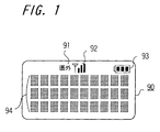
- FIG. 1 is a diagram showing an example of a display panel of a portable telephone.
- a display area 91 used for displaying letters (this means "out of area” in English) which means that the portable telephone is positioned out of a telephone call area (out of service area)
- a reception-level display area 92 used for displaying a reception level of a signal from a base station in the form of a bar graph including a plurality of bars (three bars in an example shown in FIG. 1) as well as a symbol of an antenna
- a battery-remaining-amount display area 93 used for displaying a remaining charge amount of a secondary battery by using the number of display blocks in a figure representing a battery.
- the display panel has at the remaining portion a plurality of areas 94 used for displaying numerics and letters, the plurality of the areas 94 are arranged in a dot matrix fashion with predetermined columns and rows (in this case, letters of ten columns x three rows, i.e., thirty letters).
- predetermined columns and rows in this case, letters of ten columns x three rows, i.e., thirty letters.
- numerics such as a telephone number or the like, a registered name, various messages and so on are displayed.
- the display panel thus arranged has a dimension of a lateral length of about 2 to 3 cm and a longitudinal length of about 1 to 2 cm, representation of the remaining charged amount of the secondary battery is displayed with extremely small symbols, which makes very difficult for a user to see what is displayed.
- the symbol display area becomes smaller, which makes extremely difficult for a user to see what is displayed.
- a display method of displaying a state of an electronic equipment includes a step of displaying at least two states of the electronic equipment by using change among representations of face portions different from one another.
- an electronic equipment for displaying a state of an operation and a status includes a detection unit for detecting at least two states of the electronic equipment, and a display unit for displaying the at least two states obtained from an output from the detection unit by using change among representations of face portions different from one another.
- a communication apparatus for displaying a state of an operation and a status thereof includes a detection unit for detecting at least two states of the electronic equipment, and a display unit for displaying the at least two states obtained from an output from the detection unit by using change among representations of face portions different from one another.
- the present invention is applied to a terminal apparatus of a radio telephone system.
- the radio telephone system to which the present invention is applied may be not only a general radio telephone but also a simple type radio telephone system such as a personal handy phone (PHS) or the like, and in each of the systems a basic arrangement is the same.
- FIG. 2 is a block diagram showing an arrangement of the terminal apparatus.
- the terminal apparatus has an antenna 1 used for communicating with a base station by wireless and connected to a radio communication processing unit 2.
- a transmission signal subjected by the radio communication processing unit 2 to a transmission processing is transmitted from the antenna 1 by wireless, and a signal having a predetermined frequency band and transmitted from the base station is received by the antenna 1 and then subjected to a reception processing by the radio communication processing unit 2 to obtain a reception signal.
- the reception signal subjected to the reception processing by the radio communication processing unit 2 and thereby demodulated is supplied to a data processing unit 3.
- THe data processing unit 3 subjects the supplied reception signal to a predetermined data processing to extract an audio data and a control data.
- the audio data extracted by the data processing unit is supplied to an audio processing unit 4.
- the audio processing unit 4 subjects the supplied audio data to an audio processing such as a digital-to-analog conversion, amplification or the like and supplies the processed audio signal to a speaker 5.
- the speaker 5 emanates a sound.
- An audio signal obtained form a sound the microphone 6 picks up is supplied to the audio processing unit 4.
- the audio processing unit 4 carries out the audio processing such as an analog-to-digital conversion or the like to obtain a transmission audio data and supplies the audio data to the data processing unit 3.
- the data processing unit 3 adds the supplied audio data with other data such as a control data, a synchronization data or the like to form a transmission signal, and supplies the transmission signal to the radio communication processing unit 2.
- the radio communication processing unit 2 modulates the supplied transmission signal and then frequency-converts the modulated signal into a signal having a predetermined transmission frequency, thereafter the frequency-converted transmission signal being transmitted from the antenna 1 by wireless.
- the above reception and transmission processings are carried out under the control of a control unit 11 as a system controller of the terminal apparatus.
- information about operations of respective operation units 12 such as a dial key or the like provided in the terminal apparatus are supplied to the control unit 11.
- the control unit 11 carries out various kind of processings of the radio telephone such as a call-out processing, a call-in processing or the like based on the operation information.
- the control unit 11 supplies a display control signal to a liquid crystal display (LCD) driver 13 serving as a drive circuit for a liquid crystal display panel.
- a liquid crystal display panel 20 connected to the LCD driver 13 displays letters, numerics, figures and so on based on the display control signal.
- a backlight 16 is provided on a surface on the opposite side of a display surface of the liquid crystal display panel 20.
- the backlight 16 is turned on at a predetermined time under the control of the control unit 11 to illuminate the liquid crystal display panel 20.
- a backlight incorporating light emitting diodes having a plurality of colors is employed as the backlight 16 of this embodiment.
- a red light emitting diode and a green light emitting diode are incorporated in the backlight 16 and the light emitting diodes of respective colors can individually emit light to illuminate the liquid crystal display panel 20 with red or green light and can emit both lights simultaneously to illuminate it with yellow light. Control of colors of emitted light is carried out under the control of the control unit 11.
- a secondary battery 15 as a power source for operating the terminal apparatus is incorporated in (or externally attached to) the terminal apparatus.
- a power source circuit 14 connected to the secondary battery 115 supplies to each of circuits in the terminal apparatus a power source corresponding to a voltage of each circuit.
- the power source circuit 114 is arranged so as to detect a battery state of the secondary battery 15 such as a remaining charged amount or the like based on a battery voltage, a current and so on, and supplies information about the detected battery state such as the remaining charged amount or the like to the control unit 11.
- the liquid crystal display panel 20 displays thereon not only representations directly concerning a telephone call such as a telephone number of call-out and call-in, a name corresponding to a registered telephone number and so on but also a service level representation indicating that the terminal apparatus is located within a service area, representation of the remaining charged amount of the secondary battery 15 and so on.
- control unit 11 determines a reception electric field intensity of a specific signal transmitted from a base station and determines that the terminal apparatus is located out of a service area, representation indicating that the terminal apparatus is out of an area. Contrary, when the control unit 11 determines that the terminal apparatus is located within a service area, one of plural-step representations is carried out depending upon an intensity of the level based on the received electric field intensity. Thus, the service level representations carried out. The plural-step representation of the remaining charged amount is also carried out based on the remaining charged amount of the secondary battery 15 determined by the control unit 11.
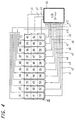
- FIG. 3 is a diagram showing an arrangement of the liquid crystal display panel 20 according to this embodiment.
- the liquid crystal display panel 20 has, at its upper portion, an area 21 used for displaying letters which means that the terminal apparatus is located out of a telephone call area (i.e., a service area, a service level display area 22 used of displaying a symbol of an antenna and a reception level of a signal from a base station in the form of a graph using a plurality of bars (three bars in this embodiment), a remaining-charged-amount display area 23 used for displaying a remaining charged amount of the secondary battery 15 by using the number of display blocks in the figure representing a battery.
- a telephone call area i.e., a service area, a service level display area 22 used of displaying a symbol of an antenna and a reception level of a signal from a base station in the form of a graph using a plurality of bars (three bars in this embodiment)
- a remaining-charged-amount display area 23 used for displaying a
- the liquid crystal display panel 20 has, at a rest portion, an area 30 used for displaying numerics and letters by using a dot matrix.
- the area 30 is provided so as to display letters of predetermined columns and rows (ten columns and three rows in this embodiment). On this display area 30 using the dot matrixes, numerics such as a telephone number, a registered name, various message and so on are displayed.
- the service level representation and the remaining charged amount representation are carried out by using a figure of a deformed face.
- a figure of a deformed face Detailed representation of a figure of a deformed face will be described later on.
- this dot-matrix display area 30 has added lines 61 to 73 provided between the display areas for the letters, and hence can display a comparatively large figure by using the entire dot-matrix display are 30.
- the dot-matrix area 30 is formed of thirty letter display areas of ten columns x three rows (letter display areas 31, 32, 33, ⁇ c ⁇ c, 60 shown in FIG. 4).
- One letter display area is formed of 35 dots of 7-dot column x 5-dot row.
- dots shown by solid squares are dots forming each of the letter display areas.
- the added vertical lines 61 to 70 are provided at vertical-direction spaces between the adjacent letter display areas and at the left end of the dot-matrix display area 30.
- the added horizontal lines 71, 72, 73 used for displaying cursors.
- dots shown by open squares are dots forming each of the added lines.
- FIG. 4 is a diagram showing a connection state of the dot-matrix display area 30 of the liquid display panel 20 and the LCD driver 13.
- a LCD driver which can display a dot matrix of twelve columns x three rows the LCD driver 13 according to this embodiment.
- the dot-matrix display area 30 is formed of the thirty letter display areas 31, 32, 33, ⁇ c, 60 of ten columns x three rows in vertical lines (5 dots x 10 : 50 lines) of dots forming the ten letter display areas of each row are connected to the LCD driver 13 by using vertical line connection unit X1 to X10 for twelve columns of prepared vertical line connection units X1 to X12 of the LCD driver 13.
- Horizontal lines (7 dots x 3 + 3 dots for the cursor display lines: 24 lines) are connected to the LCD driver 13 by using the horizontal line connection units Y1, Y2, Y3 prepared for three rows.
- Ten lines forming the added vertical lines 61 to 70 are connected to the LCD driver 13 by using ten line amount of the remaining vertical line connection units X11, X12 for two columns of the LCD driver 13.
- the LCD driver 13 which can display 8 dots including one dot for the cursor display line in the vertical direction is employed (if the driver (if a driver which can display only 7 dots in the vertical direction, then another horizontal line connection unit is used as used for the added vertical lines).
- this arrangement permits an area of 24 vertical direction dots x 60 horizontal direction dots continuously provided is formed.
- Use of this area 30 permits not only the display of letters and numerics with an area of ten columns x three rows (when only the letters and numerics are displayed, the added lines 61 to 73 are not used) but also a figure and so on continuously employing the dot-matrix display area 30 is employed.
- a processing for displaying a figure and so on by using the dot-matrix display area 30 according to this embodiment will be described. It is assumed that under the control of the control unit 11, a figure of a face representing two states of a service level and a battery remaining amount is displayed on the dot-matrix display area 30 of the liquid crystal display panel 20. Specifically, based on the service level and the battery remaining amount determined by the control unit 11, the control unit 11 supplies a display control signal used for display the figure of the corresponding face to the LCD driver 13. As shown in FIG. 5, the figure of the corresponding face is displayed at the left end of the dot-matrix display area 30. In the case shown in FIG.
- the representation indicative of a "out-of-area" state, a service level representation and a remaining charged amount representation are carried out on the display areas 21, 22, 23 on an upper portion of the liquid crystal display panel 20 similarly to that shown in FIG. 1 (while all representations are displayed in FIG. 5, practically only a portion corresponding to a state is displayed).
- the dot-matrix display area 30 as he liquid crystal display panel 20 may be prepared to display only the figure corresponding to the service level and the battery remaining amount on the dot-matrix display area 30.
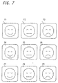
- FIG. 7 is a diagrams showing a changed state of the figure of the displayed face in this embodiment.
- the figures of faces having expressions of nine kinds are previously prepared, and one of the figures of the faces of the expressions is displayed in response to the service level and the battery remaining amount.
- the control unit 11 determines the service level by using three steps a strong electric field state, a weak electric field state and an out-of-area state and also determines the battery remaining amount by using three steps of large remaining amount, a middle remaining amount and a small remaining amount.
- the control 11 practically determines the states by using finer steps and displays the states determined as ones of the fine steps on the display areas 21, 22, 23.
- eyes of the displayed face in the figure are changed in response to the determined service level and mouths of the displayed face are changed in response to the determined battery remaining amount.
- the eyes of the laughing face (eyes formed of upward semicircles) are displayed in case of the strong electric field state.
- the eyes of a normal expression (linear-shaped eyes) are displayed in case of the weak electric field state.
- the closed eyes (eyes formed of downward semicircles) are displayed in case of the out-of-area state.
- the mouths of the laughing face are displayed in case of the large remaining amount state.
- the mouths of a normal expression (linear-shaped mouths) are displayed in case of the middle remaining amount state.
- the closed mouths (mouths formed of downward semicircles) are displayed in case of the small remaining amount state.
- Combination of the eye expressions of three kinds and the mouth expressions of three kinds permits figures P1 to P9 of face expressions of nine kinds shown in FIG. 7 to be formed, and one of the nine figures is selected in response to the service level and the battery remaining amount of the terminal apparatus at that time and then displayed on the dot-matrix display area 30 of the liquid crystal display panel 20.
- the figure P1 indicates a strong electric field and a large battery remaining amount.
- the figure P2 indicates a strong electric field and a middle battery remaining amount.
- the figure P3 indicates a strong electric field and a small battery remaining amount.
- the figure P4 indicates a weak electric field and a large battery remaining amount.
- the figure P5 indicates a weak electric field and a middle battery remaining amount.
- the figure P6 indicates a weal electric field and a small battery remaining amount.
- the figure P7 indicates a out-of-area state and a strong battery remaining amount.
- the figure P8 indicates a out-of-area state and a middle battery remaining amount.
- the figure P9 indicates a out-of-area state and a small battery remaining amount.
- FIGS. 8A to 8D are diagrams showing the display parts. Parts of a contour portion shown in FIG. 8A are commonly used in faces of respective expressions. One of parts b1, b2, b3, b4 of eyes shown in FIG. 8B is selected depending upon the expression. The parts b1 is used to display largely opened eyes and different from parts used to display the above three expressions. A case employing the parts b1 will be described later on.
- One of parts c1, c2, c3, c4 of eyes shown in FIG. 8C is selected depending upon the expression.
- the parts c1 is used to display a largely opened mouth and different from parts used to display the above three expressions. A case employing the parts b1 will be described later on.
- Parts d1, d2, d3 of a space portion shown in FIG. 8D are obtained by converting parts used for display on the added lines into parts having a size of eight vertical-direction dots x five horizontal-direction dots similar to that of the letter display area.
- One of the parts d1, d2, d3 is selected properly in response to a shape of the figure to be displayed at the time.
- the figures of the faces of nine kinds of expressions are displayed on the liquid display panel 20 to display a current state of the terminal apparatus (the service level and the battery remaining amount), and in response to the displayed figure, the color of light used for display is changed by the backlight 16 provided on the rear surface side of the liquid crystal display panel 20.
- the backlight 16 according to this embodiment provides three illumination colors of red, green and yellow for selection.
- the liquid crystal display panel 20 is illuminated with green light when the state of the terminal apparatus is comparatively satisfactory.
- the liquid crystal display panel 20 is illuminated with yellow light when the state of the terminal apparatus is comparatively unsatisfactory.
- the liquid crystal display panel 20 is illuminated with red light when the state of the terminal apparatus is considerably unsatisfactory.
- the backlight 16 employs the green light illumination.
- the backlight 16 employs a red light illumination.
- the backlight 16 employs a yellow light illumination.
- the backlight 16 employs the green light illumination.
- the backlight 16 employs a yellow light illumination.
- the backlight 16 employs a red light illumination.
- the illumination color of the backlight 16 may be changed in response only to one of the two states.
- the backlight 16 employs a green light illumination.
- the backlight 16 employs a yellow light illumination.
- the illumination color of the backlight 16 may be changed in response only to the change of the battery remaining amount.
- another example of allocating the illumination colors to the changed states may be set.
- the dot-matrix display area 30 of the liquid crystal display panel 20 When the figures of the faces described above are displayed on the dot-matrix display area 30 of the liquid crystal display panel 20, another representation may be carried out on a remaining portion of the dot-matrix display area 30.
- FIG. 9 when the figure P9 indicative of the out-of-area state is displayed at the left end of the dot-matrix display area 30, letters (which are chinese characters) may be displayed on a right-hand remaining portion of the dot-matrix display portion 30.
- the dot-matrix display area 30 is an area where dots are continuously disposed, the letters can be satisfactorily displayed by using a plurality of letter display areas continuously. Even in other states, letters and so on may be displayed together with the figure indicative of the state. Moreover, other information such as a telephone number or the like may be simultaneously displayed.
- the displayed face portion may be changed in the figure of the faces displayed on the dot-matrix display area 30 of the liquid crystal display panel 20.
- the displayed figure of the face presenting a state that the mouth thereof is being opened and closed may be displayed.
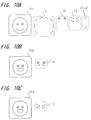
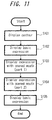
- FIG. 11 which is a flowchart therefor, a contour of the face is constantly displayed by using parts forming the contour portion of the face in step S101.
- a basic expression is displayed by using parts indicative of the closed mouth in step S102.
- the figure P11 shown in FIG. 10A is a figure of a face of the basic expression and employs contour portion parts, the parts b1 for eyes, the parts c1 for the mouth, and the parts d1, d2 for the space portions.
- a predetermined time e.g., one second
- a figure P12 shown in FIG. 10B and indicative of a face with an opened mouth is displayed by using parts indicative of a state with an opened mouth in step S103.
- parts for an upper lip portion used in the basic expression is changed to the parts e, thereby the face with the opened mouth being displayed.
- a predetermined time e.g., one second
- a figure P13 shown in FIG. 10C and indicative of a face with an opened mouth is displayed by using parts indicative of a state with an opened mouth in step S104.
- parts for an upper lip portion used in the basic expression is changed to the parts f, thereby the face with the opened mouth being displayed.
- a predetermined time e.g., one second
- the figure P11 shown in FIG. 10A and indicative of the face with the closed mouth is displayed by using parts indicative of a state with an opened mouth in step S105.
- the above processing permits the face with the opened mount to be displayed once, and hence, if necessity is caused, a representation indicating that the mouth is successively opened and closed is displayed by repeatedly carrying out the processing according to the flowchart shown in FIG. 11.
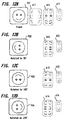
- FIGS. 12A to 12D are diagrams showing an example of a display presented when the figure is rotated.
- Figures of the faces used for the display of the rotated figures includes a figure P21 shown in FIG. 12A indicative of the face faced to the front and rotated by a rotation angle of 0°, a figure P22 shown in FIG. 12B rotated by a rotation angle of 90°, a figure P23 shown in FIG. 12C rotated by a rotation angle of 180°, and a figure P24 shown in FIG. 12D rotated by a rotation angle of 270°.
- Each of theses figures P21 to P24 is formed of the parts all for the common contour portion used for forming a contour of a face, and further formed of one of the parts b11, b12, b13, b14 for the center portion and one of the parts d11, d12, d13, d14 for the space portion both of which are selected in response to the figure.
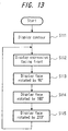
- FIG. 12 is a flowchart used to explain a processing for displaying the rotated figure.
- step S111 a contour display processing using the parts all for forming the contour portion is constantly carried out.
- step S112 the figure P21 indicative of the face faced to the front is displayed by using the parts b11 for the center portion and the parts d11 for the space portion.
- step S113 the figure P22 rotated by 90° is displayed by using the parts b12 for the center portion and the parts d12 for the space portion in step S113.
- the present invention is not limited thereto.
- the figure may be rotated in both of the above direction and the reverse direction, eg.g., the rotation direction of the figure of the face corresponding to the operation direction (rotation direction) of the operation unit may be set.
- a period used for changing the rotation angle by 90° i.g., a rotation speed of the displayed figure
- the figure may be changed by every finer angle.
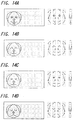
- FIGS. 14A to 14D are diagrams showing the change of the expressions of dog's faces, showing each of the two states of the terminal apparatus by four steps (in FIGS. 14A to 14D, although only four examples are shown, there are figures of expressions of total sixteen kinds because each of the examples is changed at four steps).
- FIGS. 14A to 14D At the right-hand sides of FIGS. 14A to 14D, exploded parts forming the figures are shown..
- the service level representation is displayed by using he expressions of the dog's eyes and the representation of the battery remaining amount is displayed by using the expression of the dog's mouth.
- One expression of the dog's face can also display the two states of the terminal apparatus simultaneously similarly to the above embodiment.
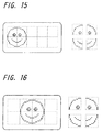
- FIG. 15 is a diagram showing an example of displaying a figure of a face by using four fonts, each of which is formed of 12 vertical-direction dots x 12 horizontal-direction dots, of a display panel. At the right-hand sides of FIG. 15, exploded parts forming the figure are shown.
- FIG. 16 is a diagram showing an example of displaying a figure of a face by using four fonts, each of which is formed of 16 vertical-direction dots x 16 horizontal-direction dots, of a display panel. At the right-hand sides of FIG. 16, exploded parts forming the figure are shown. As described above, if the shape of the face is properly set in response to the dot arrangement of the display panel to be used, then the display of the above figure can be carried out on a display panel having any dot arrangement.
- the display unit may constantly be illuminated with light of one color. There may be no display-unit illumination means such as the backlight.
- the service level and the battery remaining amount of the terminal apparatus are displayed by using two parts of the figure of the one face, the two states may be indicated by using expression of one portion.. Alternatively, more states may simultaneously be indicated by using three or larger parts of the face.
- the present invention is applied to the terminal apparatus of the radio telephone system and a simple type radio telephone system, it is needless to say that the present invention can be applied to a state display processing of a terminal apparatus of other communication system (e.g., any data transmission terminal apparatus) as long as the terminal apparatus is used in a communication system for communication via a base station.
- a terminal apparatus of other communication system e.g., any data transmission terminal apparatus
- the present invention can be applied to various electronic equipments other than such communication terminal apparatus when a plurality of states of the electronic equipment are displayed.
- a display method of the present invention it is possible to easily discriminate a plurality of stats of an equipment based on an expression of a face shown in the displayed figure.
- a signal used for displaying a figure of a face having changed expressions of different parts is generated based on an input information of at least two states of an electronic equipment and then the figure of the face is displayed on the display unit, it is possible for a user to determine a plurality of states of the electronic equipment from the figure of one face displayed on the display unit, and it is possible to easily determine a plurality of stats of the electronic equipment from the displayed figure.
- the display unit has a plurality of display areas each for displaying numerics and so on by using a dot matrix which are continuously provided therein and the figure of the face is displayed by using the plurality of continuous display areas, without preparing a display unit dedicated for the figure of the face, by using general-purpose display areas formed of dot matrixes, it is possible to display the figure of the face.
- the backlight for illuminating the display unit with colors of plural kinds and the illumination color of the backlight is changed in response to the change of the expression of the face displayed on the display unit, it is possible to inform effectively the state by using the color of the backlight.
- the figure in which the expressions different parts of the face are changed in response to the two states of the battery remaining charged amount and a radio communication state is displayed, it is possible for the user to understand at least the two states of the battery remaining charged amount and a radio communication state by watching the figure of the displayed face to thereby easily understand the state of the communication apparatus from the representation.
- the display unit has a plurality of display areas continuously provided for displaying numerics and son on by using the dot matrixes and the figure of the face is displayed thereon by using the plurality of continuous display areas, without preparing the display unit dedicated for the figure of the face, it is possible to easily display the figure of the face by using the display area already provided in the apparatus for displaying numbers and names by using the dot matrixes.
- the backlight for illuminating the display unit with light of colors of plural kinds is provided and the illumination color of the backlight is changed in response to the expression of the face, it becomes for the user to understand the changed of the expression of the face more easily and to more easily understand the remaining charged amount of the battery and the radio communication state from the displayed representation.
Landscapes
- Engineering & Computer Science (AREA)
- Computer Networks & Wireless Communication (AREA)
- Physics & Mathematics (AREA)
- Human Computer Interaction (AREA)
- Signal Processing (AREA)
- Electromagnetism (AREA)
- General Physics & Mathematics (AREA)
- Control Of Indicators Other Than Cathode Ray Tubes (AREA)
- Mobile Radio Communication Systems (AREA)
- Devices For Indicating Variable Information By Combining Individual Elements (AREA)
Applications Claiming Priority (6)
| Application Number | Priority Date | Filing Date | Title |
|---|---|---|---|
| JP1043397 | 1997-01-23 | ||
| JP1043397 | 1997-01-23 | ||
| JP10433/97 | 1997-01-23 | ||
| JP08104797A JP3671590B2 (ja) | 1997-01-23 | 1997-03-31 | 表示方法、表示装置及び通信装置 |
| JP81047/97 | 1997-03-31 | ||
| JP8104797 | 1997-03-31 |
Publications (3)
| Publication Number | Publication Date |
|---|---|
| EP0855823A2 true EP0855823A2 (fr) | 1998-07-29 |
| EP0855823A3 EP0855823A3 (fr) | 2000-01-12 |
| EP0855823B1 EP0855823B1 (fr) | 2008-10-01 |
Family
ID=26345702
Family Applications (1)
| Application Number | Title | Priority Date | Filing Date |
|---|---|---|---|
| EP98101177A Expired - Lifetime EP0855823B1 (fr) | 1997-01-23 | 1998-01-23 | Méthode d'affichage, dispositif d'affichage et méthode de communication |
Country Status (4)
| Country | Link |
|---|---|
| US (1) | US6239787B1 (fr) |
| EP (1) | EP0855823B1 (fr) |
| JP (1) | JP3671590B2 (fr) |
| DE (1) | DE69840059D1 (fr) |
Cited By (7)
| Publication number | Priority date | Publication date | Assignee | Title |
|---|---|---|---|---|
| WO2001062018A3 (fr) * | 2000-02-18 | 2002-03-28 | Vtech Mobile Ltd | Telephone mobile a interface homme-machine amelioree |
| EP1189414A4 (fr) * | 2000-03-08 | 2002-09-25 | Mitsubishi Electric Corp | Systeme de service de communication et terminal de communication specifique utilise dans ledit systeme |
| WO2003100760A1 (fr) * | 2002-05-29 | 2003-12-04 | Yamaha Hatsudoki Kabushiki Kaisha | Systeme d'indication de l'etat de produits, programme pour systeme d'indication de l'etat de produits, support d'enregistrement pour systeme d'indication de l'etat de produits |
| EP1592212A1 (fr) | 2004-04-30 | 2005-11-02 | Samsung Electronics Co., Ltd. | Procédé d'affichage d'une image écran sur un terminal mobile |
| WO2007003942A3 (fr) * | 2005-07-05 | 2007-05-18 | Vida Software S L | Interfaces utilisateur pour dispositifs electroniques |
| EP1903759A1 (fr) * | 2006-09-19 | 2008-03-26 | Samsung Electronics Co., Ltd. | Procédé pour le contrôle de l'affichage d'une horloge analogique et terminal de communication mobile l'utilisant |
| EP1860854A3 (fr) * | 2006-05-25 | 2010-08-04 | Samsung Electronics Co., Ltd. | Procédé pour composer un numéro sur l'écran et structure de couche pour terminal mobile |
Families Citing this family (23)
| Publication number | Priority date | Publication date | Assignee | Title |
|---|---|---|---|---|
| US6494827B1 (en) * | 1998-10-29 | 2002-12-17 | Olympus Optical Co., Ltd. | Endoscope device and operation apparatus |
| KR100534672B1 (ko) * | 1999-05-26 | 2005-12-08 | 삼성전자주식회사 | 온 스크린 디스플레이를 피벗시키기 위한 기능을 갖는 영상표시장치 |
| US6321562B1 (en) * | 1999-06-29 | 2001-11-27 | Calsonic Kansei Corporation | Evaporator of automotive air-conditioner |
| US6490465B1 (en) * | 1999-09-09 | 2002-12-03 | Qualcomm, Inc. | Mobile telephone status menu with antenna position indication |
| JP3483026B2 (ja) * | 1999-12-08 | 2004-01-06 | Necモバイリング株式会社 | 携帯端末機及び携帯端末機におけるバックライト表示方法 |
| JP3580206B2 (ja) * | 2000-02-01 | 2004-10-20 | 日本電気株式会社 | 携帯電話装置及び携帯電話装置の表示動作方法並びに携帯電話装置の表示動作プログラムを記録した記憶媒体 |
| KR100388944B1 (ko) * | 2000-06-26 | 2003-06-25 | 삼성전자주식회사 | 전자기기 상태 표시방법 및 장치 |
| BR8100823U (pt) * | 2001-05-17 | 2003-02-04 | Dalton Swain Conselvan | Disposição introduzida em inversor de display |
| US7714824B2 (en) * | 2001-06-11 | 2010-05-11 | Genoa Color Technologies Ltd. | Multi-primary display with spectrally adapted back-illumination |
| US7003040B2 (en) * | 2002-09-24 | 2006-02-21 | Lg Electronics Inc. | System and method for multiplexing media information over a network using reduced communications resources and prior knowledge/experience of a called or calling party |
| FI20021759A0 (fi) * | 2002-10-03 | 2002-10-03 | Nokia Corp | Menetelmä ja käyttöliittymä tekstin syöttämiseen |
| EP2290930A3 (fr) | 2002-10-04 | 2012-02-22 | Nec Corporation | Téléphone portable et méthode de présentation de charactères pour celui-ci |
| US7002604B1 (en) * | 2002-11-04 | 2006-02-21 | Savaje Technologies, Inc. | Screen rotation |
| US6802757B1 (en) | 2003-05-01 | 2004-10-12 | The First Years, Inc. | Developmental toy |
| US7777764B2 (en) * | 2003-09-11 | 2010-08-17 | Sharp Kabushiki Kaisha | Portable display device |
| JP4503553B2 (ja) * | 2006-04-06 | 2010-07-14 | 株式会社エヌ・ティ・ティ・ドコモ | 通信端末、通信システム及び制御方法 |
| JP2007336256A (ja) * | 2006-06-15 | 2007-12-27 | Toshiba Corp | 無線通信端末 |
| US20080079716A1 (en) * | 2006-09-29 | 2008-04-03 | Lynch Thomas W | Modulating facial expressions to form a rendered face |
| KR20120040946A (ko) * | 2010-10-20 | 2012-04-30 | 삼성전자주식회사 | 휴대단말기의 도트 led 이미지 생성 장치 및 방법 |
| USD682882S1 (en) * | 2012-03-30 | 2013-05-21 | Microsoft Corporation | Display screen with icon |
| WO2013157297A1 (fr) * | 2012-04-18 | 2013-10-24 | ソニー株式会社 | Dispositif de traitement d'informations, procédé de traitement d'informations, et programme |
| US9474956B2 (en) | 2013-07-22 | 2016-10-25 | Misfit, Inc. | Methods and systems for displaying representations of facial expressions and activity indicators on devices |
| WO2017069551A1 (fr) * | 2015-10-23 | 2017-04-27 | Samsung Electronics Co., Ltd. | Appareil d'affichage d'image et procédé d'exploitation correspondant |
Family Cites Families (9)
| Publication number | Priority date | Publication date | Assignee | Title |
|---|---|---|---|---|
| US4642710A (en) * | 1985-03-15 | 1987-02-10 | Milton Bradley International, Inc. | Animated display controlled by an audio device |
| JP3279556B2 (ja) * | 1990-07-06 | 2002-04-30 | 株式会社日立製作所 | データ編集方法 |
| US5406268A (en) * | 1991-06-12 | 1995-04-11 | Iqv Corporation | Portable microcomputer with power-sparing system of illuminated indicators |
| GB9125331D0 (en) * | 1991-11-28 | 1992-01-29 | Shaye Communications Ltd | Illumination of displays |
| JPH0651129A (ja) * | 1992-07-27 | 1994-02-25 | Inoue Denki Kk | 照明装置 |
| US5805981A (en) * | 1994-06-06 | 1998-09-08 | Casio Computer Co., Ltd. | Communication terminal and communication system with image display and image storage section |
| JPH0965224A (ja) * | 1995-08-24 | 1997-03-07 | Hitachi Ltd | テレビ受像機 |
| JPH09331561A (ja) * | 1996-06-12 | 1997-12-22 | Nec Shizuoka Ltd | 表示付き無線選択呼出受信機 |
| US5870683A (en) * | 1996-09-18 | 1999-02-09 | Nokia Mobile Phones Limited | Mobile station having method and apparatus for displaying user-selectable animation sequence |
-
1997
- 1997-03-31 JP JP08104797A patent/JP3671590B2/ja not_active Expired - Fee Related
-
1998
- 1998-01-23 DE DE69840059T patent/DE69840059D1/de not_active Expired - Lifetime
- 1998-01-23 EP EP98101177A patent/EP0855823B1/fr not_active Expired - Lifetime
- 1998-01-26 US US09/010,338 patent/US6239787B1/en not_active Expired - Lifetime
Cited By (11)
| Publication number | Priority date | Publication date | Assignee | Title |
|---|---|---|---|---|
| WO2001062018A3 (fr) * | 2000-02-18 | 2002-03-28 | Vtech Mobile Ltd | Telephone mobile a interface homme-machine amelioree |
| EP1189414A4 (fr) * | 2000-03-08 | 2002-09-25 | Mitsubishi Electric Corp | Systeme de service de communication et terminal de communication specifique utilise dans ledit systeme |
| US7046645B1 (en) | 2000-03-08 | 2006-05-16 | Mitsubishi Denki Kabushiki Kaisha | Communication service system and dedicated communication terminal used in it |
| WO2003100760A1 (fr) * | 2002-05-29 | 2003-12-04 | Yamaha Hatsudoki Kabushiki Kaisha | Systeme d'indication de l'etat de produits, programme pour systeme d'indication de l'etat de produits, support d'enregistrement pour systeme d'indication de l'etat de produits |
| US7242312B2 (en) | 2002-05-29 | 2007-07-10 | Yamaha Hatsudoki Kabushiki Kaisha | Product state display system, and program and recording medium for the same |
| EP1592212A1 (fr) | 2004-04-30 | 2005-11-02 | Samsung Electronics Co., Ltd. | Procédé d'affichage d'une image écran sur un terminal mobile |
| US7555717B2 (en) | 2004-04-30 | 2009-06-30 | Samsung Electronics Co., Ltd. | Method for displaying screen image on mobile terminal |
| WO2007003942A3 (fr) * | 2005-07-05 | 2007-05-18 | Vida Software S L | Interfaces utilisateur pour dispositifs electroniques |
| US20100180202A1 (en) * | 2005-07-05 | 2010-07-15 | Vida Software S.L. | User Interfaces for Electronic Devices |
| EP1860854A3 (fr) * | 2006-05-25 | 2010-08-04 | Samsung Electronics Co., Ltd. | Procédé pour composer un numéro sur l'écran et structure de couche pour terminal mobile |
| EP1903759A1 (fr) * | 2006-09-19 | 2008-03-26 | Samsung Electronics Co., Ltd. | Procédé pour le contrôle de l'affichage d'une horloge analogique et terminal de communication mobile l'utilisant |
Also Published As
| Publication number | Publication date |
|---|---|
| DE69840059D1 (de) | 2008-11-13 |
| JP3671590B2 (ja) | 2005-07-13 |
| EP0855823A3 (fr) | 2000-01-12 |
| EP0855823B1 (fr) | 2008-10-01 |
| US6239787B1 (en) | 2001-05-29 |
| JPH10271559A (ja) | 1998-10-09 |
Similar Documents
| Publication | Publication Date | Title |
|---|---|---|
| EP0855823A2 (fr) | Méthode d'affichage, dispositif d'affichage et méthode de communication | |
| US5584070A (en) | Wireless pager with separable receiver unit and transmitter unit | |
| EP1020062B1 (fr) | Alarme visuelle pour module de communication | |
| EP1271286A3 (fr) | Terminal d'information portable | |
| CA2353161A1 (fr) | Interface utilisateur et methode permettant d'afficher de courts messages sur un dispositif sans fil | |
| RU2003108740A (ru) | Персонализация мобильного телефона | |
| CA2321039A1 (fr) | Terminal de communication | |
| EP1542436A1 (fr) | ASIC pour jeu de lumière | |
| MY113251A (en) | Communications terminal equipment for receiving and sending message information and the control method thereof | |
| WO2002091714A3 (fr) | Dispositif radio mobile | |
| GB2373977A (en) | Displaying "wallpaper" on a mobile telephone display | |
| US20070024538A1 (en) | Display Apparatus and Display Control Method | |
| EP1178650A3 (fr) | Terminal d'information portable | |
| EP1610208A1 (fr) | Appareil d'entrée à touches pour entrer des numéros plus facilement et un dispositif électronique correspondant | |
| EP0743624B1 (fr) | Récepteur d'appel sélectif radio avec fonction d'affichage et procédé d'affichage d'information par image | |
| JPH1039842A (ja) | 液晶表示装置を有する端末 | |
| US6658270B1 (en) | Displayer-embedded cellular phone battery | |
| JP2570494B2 (ja) | 表示付選択呼出受信機 | |
| JPH10126827A (ja) | 無線呼出受信装置 | |
| IE883537L (en) | Communication device | |
| KR100617794B1 (ko) | 휴대용 무선 단말기에서 디스플레이 소자의 배경조명 색상선택 방법 | |
| KR100774477B1 (ko) | 다중 디스플레이 수단을 갖는 이동통신 단말기 | |
| JP4234891B2 (ja) | 移動通信端末 | |
| JP2006119212A (ja) | 電子機器 | |
| JP2001346255A (ja) | 通信方法およびその装置 |
Legal Events
| Date | Code | Title | Description |
|---|---|---|---|
| PUAI | Public reference made under article 153(3) epc to a published international application that has entered the european phase |
Free format text: ORIGINAL CODE: 0009012 |
|
| AK | Designated contracting states |
Kind code of ref document: A2 Designated state(s): DE FR GB |
|
| AX | Request for extension of the european patent |
Free format text: AL;LT;LV;MK;RO;SI |
|
| RHK1 | Main classification (correction) |
Ipc: H04M 1/72 |
|
| PUAL | Search report despatched |
Free format text: ORIGINAL CODE: 0009013 |
|
| AK | Designated contracting states |
Kind code of ref document: A3 Designated state(s): AT BE CH DE DK ES FI FR GB GR IE IT LI LU MC NL PT SE |
|
| AX | Request for extension of the european patent |
Free format text: AL;LT;LV;MK;RO;SI |
|
| 17P | Request for examination filed |
Effective date: 20000529 |
|
| AKX | Designation fees paid |
Free format text: DE FR GB |
|
| 17Q | First examination report despatched |
Effective date: 20050511 |
|
| 17Q | First examination report despatched |
Effective date: 20050511 |
|
| GRAP | Despatch of communication of intention to grant a patent |
Free format text: ORIGINAL CODE: EPIDOSNIGR1 |
|
| GRAS | Grant fee paid |
Free format text: ORIGINAL CODE: EPIDOSNIGR3 |
|
| GRAA | (expected) grant |
Free format text: ORIGINAL CODE: 0009210 |
|
| AK | Designated contracting states |
Kind code of ref document: B1 Designated state(s): DE FR GB |
|
| REG | Reference to a national code |
Ref country code: GB Ref legal event code: FG4D |
|
| REF | Corresponds to: |
Ref document number: 69840059 Country of ref document: DE Date of ref document: 20081113 Kind code of ref document: P |
|
| PLBE | No opposition filed within time limit |
Free format text: ORIGINAL CODE: 0009261 |
|
| STAA | Information on the status of an ep patent application or granted ep patent |
Free format text: STATUS: NO OPPOSITION FILED WITHIN TIME LIMIT |
|
| 26N | No opposition filed |
Effective date: 20090702 |
|
| REG | Reference to a national code |
Ref country code: GB Ref legal event code: 746 Effective date: 20091130 |
|
| PGFP | Annual fee paid to national office [announced via postgrant information from national office to epo] |
Ref country code: FR Payment date: 20130213 Year of fee payment: 16 Ref country code: GB Payment date: 20130122 Year of fee payment: 16 Ref country code: DE Payment date: 20130122 Year of fee payment: 16 |
|
| REG | Reference to a national code |
Ref country code: DE Ref legal event code: R119 Ref document number: 69840059 Country of ref document: DE |
|
| GBPC | Gb: european patent ceased through non-payment of renewal fee |
Effective date: 20140123 |
|
| REG | Reference to a national code |
Ref country code: DE Ref legal event code: R119 Ref document number: 69840059 Country of ref document: DE Effective date: 20140801 |
|
| PG25 | Lapsed in a contracting state [announced via postgrant information from national office to epo] |
Ref country code: DE Free format text: LAPSE BECAUSE OF NON-PAYMENT OF DUE FEES Effective date: 20140801 |
|
| REG | Reference to a national code |
Ref country code: FR Ref legal event code: ST Effective date: 20140930 |
|
| PG25 | Lapsed in a contracting state [announced via postgrant information from national office to epo] |
Ref country code: FR Free format text: LAPSE BECAUSE OF NON-PAYMENT OF DUE FEES Effective date: 20140131 Ref country code: GB Free format text: LAPSE BECAUSE OF NON-PAYMENT OF DUE FEES Effective date: 20140123 |