EP0855866B1 - Fermoir a bouton - Google Patents
Fermoir a bouton Download PDFInfo
- Publication number
- EP0855866B1 EP0855866B1 EP97921578A EP97921578A EP0855866B1 EP 0855866 B1 EP0855866 B1 EP 0855866B1 EP 97921578 A EP97921578 A EP 97921578A EP 97921578 A EP97921578 A EP 97921578A EP 0855866 B1 EP0855866 B1 EP 0855866B1
- Authority
- EP
- European Patent Office
- Prior art keywords
- clasp
- unfolding
- locking
- arm
- base blade
- Prior art date
- Legal status (The legal status is an assumption and is not a legal conclusion. Google has not performed a legal analysis and makes no representation as to the accuracy of the status listed.)
- Expired - Lifetime
Links
- 230000000717 retained effect Effects 0.000 claims description 2
- 210000000707 wrist Anatomy 0.000 claims 2
- 230000007246 mechanism Effects 0.000 description 8
- 230000000694 effects Effects 0.000 description 4
- 230000000295 complement effect Effects 0.000 description 2
- 238000010276 construction Methods 0.000 description 2
- 230000003213 activating effect Effects 0.000 description 1
- 238000005452 bending Methods 0.000 description 1
- 230000006835 compression Effects 0.000 description 1
- 238000007906 compression Methods 0.000 description 1
- 230000003247 decreasing effect Effects 0.000 description 1
- 238000006073 displacement reaction Methods 0.000 description 1
- 238000004880 explosion Methods 0.000 description 1
- 238000003754 machining Methods 0.000 description 1
- 238000012423 maintenance Methods 0.000 description 1
- 230000007257 malfunction Effects 0.000 description 1
- 238000004519 manufacturing process Methods 0.000 description 1
- 239000000463 material Substances 0.000 description 1
- 239000007769 metal material Substances 0.000 description 1
- 238000000034 method Methods 0.000 description 1
- 230000002441 reversible effect Effects 0.000 description 1
- 230000035943 smell Effects 0.000 description 1
- 239000007787 solid Substances 0.000 description 1
- 229910001220 stainless steel Inorganic materials 0.000 description 1
- 239000010935 stainless steel Substances 0.000 description 1
Images


Classifications
-
- A—HUMAN NECESSITIES
- A44—HABERDASHERY; JEWELLERY
- A44C—PERSONAL ADORNMENTS, e.g. JEWELLERY; COINS
- A44C5/00—Bracelets; Wrist-watch straps; Fastenings for bracelets or wrist-watch straps
- A44C5/18—Fasteners for straps, chains or the like
- A44C5/22—Fasteners for straps, chains or the like for closed straps
- A44C5/24—Fasteners for straps, chains or the like for closed straps with folding devices
-
- Y—GENERAL TAGGING OF NEW TECHNOLOGICAL DEVELOPMENTS; GENERAL TAGGING OF CROSS-SECTIONAL TECHNOLOGIES SPANNING OVER SEVERAL SECTIONS OF THE IPC; TECHNICAL SUBJECTS COVERED BY FORMER USPC CROSS-REFERENCE ART COLLECTIONS [XRACs] AND DIGESTS
- Y10—TECHNICAL SUBJECTS COVERED BY FORMER USPC
- Y10T—TECHNICAL SUBJECTS COVERED BY FORMER US CLASSIFICATION
- Y10T24/00—Buckles, buttons, clasps, etc.
- Y10T24/21—Strap tighteners
- Y10T24/2143—Strap-attached folding lever
- Y10T24/2155—Jewelry-watch straps
-
- Y—GENERAL TAGGING OF NEW TECHNOLOGICAL DEVELOPMENTS; GENERAL TAGGING OF CROSS-SECTIONAL TECHNOLOGIES SPANNING OVER SEVERAL SECTIONS OF THE IPC; TECHNICAL SUBJECTS COVERED BY FORMER USPC CROSS-REFERENCE ART COLLECTIONS [XRACs] AND DIGESTS
- Y10—TECHNICAL SUBJECTS COVERED BY FORMER USPC
- Y10T—TECHNICAL SUBJECTS COVERED BY FORMER US CLASSIFICATION
- Y10T24/00—Buckles, buttons, clasps, etc.
- Y10T24/21—Strap tighteners
- Y10T24/2166—Jewelry
-
- Y—GENERAL TAGGING OF NEW TECHNOLOGICAL DEVELOPMENTS; GENERAL TAGGING OF CROSS-SECTIONAL TECHNOLOGIES SPANNING OVER SEVERAL SECTIONS OF THE IPC; TECHNICAL SUBJECTS COVERED BY FORMER USPC CROSS-REFERENCE ART COLLECTIONS [XRACs] AND DIGESTS
- Y10—TECHNICAL SUBJECTS COVERED BY FORMER USPC
- Y10T—TECHNICAL SUBJECTS COVERED BY FORMER US CLASSIFICATION
- Y10T24/00—Buckles, buttons, clasps, etc.
- Y10T24/47—Strap-end-attaching devices
- Y10T24/4782—Watch strap
Definitions
- the invention relates to closures specially used to provide a bracelet clasp closure according to claims.
- Document FR 2,723,824 describes a folding clasp comprising a blade base consisting of two parallel parts whose ends are connected by rods receiving articulated arms located between said parts of the blade based. The two arms cooperate by snap-fastening with pins for the closure of the clasp, pins carried by a transverse and through bolt said parallel parts.
- This latching device has the same disadvantages than that of document EP 0.509.938 and moreover the stability transverse parallel parts forming the base blade is not guaranteed made of their great length and that they are connected only at their ends.
- the document CH 684.151 describes a folding clasp comprising two arms leaflets articulated at the ends of a central stretcher.
- This clasp has mounted on the central stretcher two latches sliding transversely by compared to this central stretcher, controlled by lifters, subject to action a spring tending to separate them from each other.
- the use of spring leads always risks of malfunction and complicates construction.
- a third drawback lies in the reliability and security of the closures. known folding clasp and snap. The locking forces are difficult to adjust, presenting a risk of inadvertent opening of the clasp.
- the objective of the present invention is to provide a solution to these problems creating a folding clasp, for general application, for example for a wristwatch, of a particularly compact and compatible construction with known and proven manufacturing techniques.
- FIGS 1a to 1c and 2a, 2b show a perspective and exploding view of a detail of different preferred embodiments of a folding clasp.
- Said folding clasp comprises at least one folding arm 1,2 articulated in an opening / closing plane OO ' with respect to a base blade 3.
- Said at least one folding arm 1,2 is removable around at least one axis articulation with at least one hinge rod 1.5,2.5.
- the clasp comprises two folding arms 1, 2 are removable around two articulation axes with two hinge pins 1.5, 2.5. It is of course possible, while remaining within the scope of the invention, to produce a clasp with only one folding arm.
- the folding clasp is characterized by a locking means 4 arranged on the base blade 3.
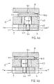
- Figures 2a and 2b distinguish between two preferred embodiments of a folding clasp.
- a first embodiment according to FIG. 2a shows a locking effected essentially by a moving part 4.5 of the locking means 4 with at least one inclined face tip 1.1,2.1 of said at least one folding arm 1.2 folded over the base blade 3 .
- This lock will be described in more detail with the aid of figures 3a and 3b.
- Another embodiment according to FIG. 2b also shows an initial locking effect carried out by a guide piece 4.3 of the locking means 4 with at least one cylindrical rod 1.40, 2.40 of said at least one folding arm 1.2 folded over the blade of base 3. This initial locking will be described in more detail with the aid of FIGS. 5a and 5b.
- These two interlocks are complementary.
- Said locking of the moving part 4.5 with at least one inclined end piece 1.1,2.1 is carried out by moving said moving part 4.5 in a plane TT ' substantially perpendicular to the opening / closing plane OO' of said at least one folding arm 1,2 .
- the plane TT ' is perpendicular (lateral) to the longitudinal direction of the clasp and respectively of a bracelet of a wristwatch.
- said moving part 4.5 slides on at least one lateral axis 4.1, 4.4.2 of the locking means 4. So that said moving part 4.5 is easily accessible, said locking means 4 comprises a button 4.4 securely fixed to said moving part 4.5.
- Said locking means 4 further comprises a guide part 4.3 having an opening 4.31 elongated in the direction of the plane TT ' , so that said button 4.4 being arranged inside said opening 4.31 is guided with play and maintained during the locking of said at least one folding arm 1,2.
- Said initial locking of the guide piece 4.3 of the locking means 4 with at least one cylindrical rod 1.40, 2.40 is carried out by moving said at least one folding arm 1.2 in the opening / closing plane OO '.
- a cylindrical rod 1.40,2.40 is fixed on the side of a fastener 1.4,2.4 of two folding arms 1,2.
- two cylindrical rods 1.40, 2.40 carry out a first initial locking or locking with recesses 4.30 of the guide part 4.3.
- Figures 3a and 3b show in a schematic top view a detail of the opening / closing mechanism of a folding clasp.
- An inclined end face 1.1.2.1 of said at least one folding arm 1.2 and at least one inclined end end corresponding 4.51,4.52 of said movable part 4.5 are V-shaped open or conical.
- Said inclined end faces 1.1,2.1,4.51,4.52 in the form of a V-shaped open or conical shape are arranged at a constant inclination angle relative to the plane TT ′, so that their wide conical side L corresponds to an unlocking position of the clasp (see Figure 3a) and that their narrow conical side F corresponds to a locking position of the clasp (see Figure 3b).
- the inclined end faces 1.1,2.1,4.51,4.52 are planar.
- the locking is done under the effect of a pinching of the moving part 4.5 against the at least one inclined face tip 1.1,2.1 of said at least one folding arm 1,2 in the locking position on the narrow conical side F.
- the moving part 4.5 is like a small mobile carriage which slides on at least one axis 4.1,4.2.
- the locking means 4 is either in the unlocked position on the wide conical side L (see FIGS. 3a and 4a), or in the locked position of the narrow conical side F (see Figures 3b and 4b).
- the movable part 4.5 is slightly pinched under the guide part 4.3 allowing the maintenance in the unlocked position. This can be done thanks to an additional thickness under the guide piece 4.3.
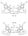
- Figures 5a and 5b show a schematic view of another detail of the opening / closing mechanism of a folding clasp.
- a cylindrical rod 1.40, 2.40 of said at least one folding arm 1.2 and at least one corresponding recess 4.30 of the guide piece 4.3 are arranged so that during movement of said at least one folding arm 1.2 in a plane opening / closing OO ' an initial locking is done by snapping each of said cylindrical rods 1.40,2.40 into a recess 4.30.
- the clasp comprises two folding arms 1,2 and each folding arm 1,2 is provided with a cylindrical rod 1,40,2.40.
- a guide part 4.3 is provided, having two recesses 4.30 on the side of the folding arms 1,2.
- the recesses 4.30 are adapted to the geometric shape of the cylindrical rods 1.40,2.40. It is entirely possible, without going beyond the scope of the invention, to provide different geometric shapes, for example rods and / or oval or even square recesses.
- the cylindrical rods 1.40, 2.40 may be in the form of thin-walled tubes. Solid rods or hollow rods forming elastic tubes can be split, for example in their longitudinal direction (see for example the cylindrical rod 2.40 according to Figures 5a and 5b). The application of slots is optional, it is possible to provide rods or elastic tubes which are not split (see for example the cylindrical rod 1.40 according to FIGS. 5a and 5b). These examples are shown by way of example.
- cylindrical rods or elastic tubes allow a variation in the elasticity of the cylindrical rods or elastic tubes.
- shape of such slots is not limited to linear slots in the longitudinal direction (helix, spiral or bias shapes are possible) and that the slots should not extend over the entire length.
- Such elastic tubes are preferably metallic and their thin wall is preferably 0.15 millimeter thick. For a smaller thickness, the maximum bending stress becomes too large (the deformation force is too high and the snap-fastening becomes difficult), for a larger thickness, the elastic constant of an elastic tube becomes too large (the wall thin deforms beyond the reversible elastic limit and the snap is not well accentuated).
- an elastic tube made with a metallic material for example an elastic tube made of stainless steel
- a thickness of 0.15 millimeters represents an ideal choice, allowing both a well defined closing or latching force (which smells good, without being too strong or too weak) while ensuring easy machining of the locking means.
- a split rod and / or a split tube gives an additional degree of freedom to the initial locking.
- the quality of a clasp is not only defined by its purely technical characteristics but also by its impression it makes on the user. Unlike known clasps, which do not use such an initial locking with cylindrical rods or elastic tubes and with a couple of different materials, it is possible to individually adjust the forces and in particular to adjust the characteristics of latching of the folding clasp.
- the cylindrical rods 1.40,2.40 are arranged near the fasteners 1.4,2.4.
- the rods 1.40,2.40 are added welded to the clips 1.4,2.4.
- Other fixing means are of course possible without going beyond the scope of the invention.
- This position at the end of the folding arms 1,2 allows in any circumstance a first snap-in or initial locking of the cylindrical rods 1.40, 2.40 of the folding arms 1.2 with the guide piece 4.3 of the locking means 4 before the locking of the faces inclined end piece 1.1,2.1 of the folding arms 1,2 with the movable part 4.5 of the locking means 4.
- This position of the cylindrical rods 1.40,2.40 half concealed by the fasteners 1.4,2.4 is particularly aesthetic and refined, which is desired by the user.
- Figure 5a shows this initial locking before the latching of the cylindrical rods 1.40,2.40 in the recesses 4.30
- Figure 5b shows the cylindrical rods 1.40,2.40 after the latching in the recesses 4.30
- the guide piece 4.3 is firmly fixed on the base blade 3.
- the folding arms 1,2 can be elastic to allow the more or less elastic cylindrical rods 1.40,2.40 to exceed the protruding edge of the recesses 4.30.
- Figures 4a and 4b show a detail view of a locking security of a folding clasp.
- a first folding arm 1 comprises a cover 10 articulated with respect to said first folding arm 1.
- Said cover 10 is removable around a hinge pin with a hinge rod 10.2. Said cover 10 folded over the locking means 4 provides security for locking said at least one folding arm 1,2.
- This locking security is complementary. In particular, this locking security is optional and it is possible, while remaining within the scope of the invention, to make a clasp with or without locking security.
- Said cover 10 includes an asymmetrical bottom 10.1.
- Said asymmetrical bottom 10.1 is provided with a boss 10.12 on the wide conical side L of said inclined end faces 1.1,2.1,4.51,4.52 (see FIGS. 1a to 3b) corresponding to an unlocking position of the clasp (see FIG. 4a) and said asymmetrical bottom 10.1 is hollowed out on the narrow conical side F of said inclined faces tip 1.1,2.1,4.51,4.52 corresponding to a locking position of the clasp (see FIG. 4b), so that said asymmetrical bottom 10.1 of a cover 10 folded down maintains the button 4.4 on the narrow conical side F of said inclined faces end piece 1.1,2.1,4.51,4.52 corresponding to a locking position of the clasp.
- This locking mechanism is characterized by dual-function security.
- the cover 10 with asymmetrical bottom 10.1 guarantees at the same time that the cover 10 cannot be folded down on a locking means 4 in the unlocked position on the wide conical side L (see FIGS. 3a and 4a), because the button 4.4 would act obstacle to the boss 10.12 of the cover 10 and the cover 10 reinforces the locking of the locking means 4 in the locked position on the narrow conical side F (see FIGS. 3b and 4b) avoiding inadvertent opening of the clasp.
- Said folded cover 10 is retained by snap-fastening with at least one fixing means arranged on a second folding arm 2 (see FIGS. 2a and 2b) or on the base blade 3.
- a fixing means 11.1, 11.2 are provided. and each fastening means 11.1,11.2 comprises a housing containing a ball 11.3 arranged at one end of a straight spring 11.4 . The other end of the spring 11.4 is fixed to the bottom of the housing.
- Such a fixing means 11.1, 11.2 is arranged inside a guide sleeve of a second folding arm 2 (see FIGS. 2a and 2b ) or of the base blade 3, so that the balls 11.3 protrude the guide sleeve and exert a fixing force on the folded cover 10 .
- the folded cover 10 is fixed by the spring force of the straight springs 11.4 . It is of course possible to use other embodiments of known fixing means that go beyond the scope of the invention.
- the folding clasp is made with a minimum number of elements that can easily be replaced or adjusted.
- the locking / unlocking force can be easily adjusted by changing (increasing / decreasing) the angle of inclination of the inclined faces 1.1.1.2,4.51,4.52 of V-shaped open or conical (see Figures 3a and 3b).
- the folding clasp is characterized by a particularly easy and safe opening / closing mechanism.
- the displacement of the locking means 4 in the plane TT ′ does not cause wear of said notching device.
- the folding clasp is preferably metallic.
- the folding clasp can be attached to the ends of a flexible link bracelet of a wristwatch.
- Such links 9,9 ′, 11,11 ′ of two bracelet strands are shown in FIGS. 2a and 2b.
- knurled axes 9.11 driven keep the links 9,9 ', 11,11' together.
- screws 9,1,9.2 are provided for fixing the bracelets strand to attachments 1.4,2.4 of the folding arms 1,2.
Landscapes
- Buckles (AREA)
- Purses, Travelling Bags, Baskets, Or Suitcases (AREA)
Description
- les figures 1a à 1c montrent une vue en perspective d'un détail d'un mode de réalisation préféré d'un fermoir dépliant.
- les figures 2a et 2b montrent une vue en explosion d'un détail de deux modes de réalisation préférés d'un fermoir dépliant.
- les figures 3a et 3b montrent une vue de dessus schématisée d'un détail du mécanisme d'ouverture/fermeture d'un mode de réalisation préféré d'un fermoir dépliant.
- les figures 4a et 4b montrent une vue schématisée d'un détail d'une sécurité du verrouillage d'un mode de réalisation préféré d'un fermoir dépliant.
- les figures 5a et 5b montrent une vue schématisée d'un détail du mécanisme d'ouverture/fermeture d'un mode de réalisation préféré d'un fermoir dépliant.
Claims (15)
- Fermoir dépliant comportant une lame de base (3) et au moins un bras dépliant (1;2) articulé par l'une de ses extrémités sur une extrémité de la lame de base (3) et destiné à être relié par son autre extrémité à une extrémité d'un bracelet; ce fermoir comportant un dispositif de verrouillage (4) solidaire de la lame de base (3) comprenant un verrou (4.5) déplaçable transversalement par rapport à ladite lame de base entre une position de verrouillage et une position de déverrouillage du fermoir, caractérisé par le fait que la lame de base est constituée de deux pièces parallèles (3) dont les extrémités sont reliées deux à deux par des tiges (1.5 ; 2.5) ; que le (1) ou les (1,2) bras sont articulés chacun sur l'une des tiges (1.5 ;2.5) par l'une de leurs extrémités, et située entre lesdites pièces parallèles (3) formant la lame de base ; par le fait que lesdites pièces parallèles (3) formant la lame de base sont reliées dans leur partie médiane par au moins un axe transversal (4.1 ;4.2) ; ledit dispositif de verrouillage comporte une pièce de guidage (4.3) solidaire de la lame de base (3) comportant une fente traversante (4.31) s'étendant transversalement par rapport à la lame de base (3) donnant passage à la tige d'un bouton (4.4) dont l'extrémité est solidaire du verrou (4,5); par le fait que l'ensemble formé par le verrou (4.5) et le bouton (4.4) coulisse dans la pièce de guidage (4.3) perpendiculairement à ladite lame de base (3); par le fait que ce verrou (4.5) comporte au moins une face de verrouillage (4.51;4.52); et par le fait que l'extrémité libre du ou des bras (1;2) comporte une face terminale inclinée (1.1;2.1) coopérant avec la face de verrouillage (4.51;4.52) du verrou (4.5) en position fermée et verrouillée du fermoir.
- Fermoir dépliant selon la revendication 1, caractérisé en ce que le fermoir comprend deux bras dépliants (1,2).
- Fermoir dépliant selon la revendication 1 ou 2, caractérisé en ce que ladite face inclinée embout (1.1,2.1) dudit au moins un bras dépliant (1,2) et au moins une face inclinée embout (4.51,4.52) correspondante de ladite pièce mobile (4.5) sont en forme de V dégagées ou coniques.
- Fermoir dépliant selon la revendication 3, caractérisé en ce que lesdites faces inclinées embout (1.1,2.1,4.51,4.52) en forme de V dégagées ou coniques sont agencées sous un angle d'inclinaison constant par rapport au plan (TT'), de façon que leur côté conique large (L) correspond à une position de déverrouillage du fermoir et que leur côté conique étroit (F) correspond à une position de verrouillage du fermoir.
- Fermoir dépliant selon une des revendications 1 à 4, caractérisé en ce que ladite pièce mobile (4.5) coulisse sur au moins un axe latéral (4.1,4.2) du moyen de verrouillage (4).
- Fermoir dépliant selon une des revendications 1 à 5, caractérisé en ce que ledit moyen de verrouillage (4) comprend un bouton (4.4) solidement fixé à ladite pièce mobile (4.5).
- Fermoir dépliant selon la revendication 6, caractérisé en ce que ledit moyen de verrouillage (4) comprend une pièce de guidage (4.3) ayant une ouverture (4.31) allongée dans le plan (TT'), ledit bouton (4.4) est agencé à l'intérieure de ladite ouverture (4.31), permettant le guidage et maintien dudit bouton (4.4) lors du verrouillage dudit au moins un bras dépliant (1,2).
- Fermoir dépliant selon une des revendications 1 à 7, caractérisé en ce que le moyen de verrouillage (4) comprend une pièce de guidage (4.3) permettant un verrouillage initial d'au moins une tige cylindrique (1.40,2.40) dudit au moins un bras dépliant (1,2) rabattu avec des évidements (4.30) de ladite pièce de guidage (4.3).
- Fermoir dépliant selon la revendication 8, caractérisé en ce que ladite au moins une tige cylindrique (1.40,2.40) est agencée près d'une attaches (1.4,2.4) à l'extrémité dudit au moins un bras dépliants (1,2) permettant en toute circonstance un premier encliquetage ou verrouillage initial de ladite tige cylindrique (1.40,2.40) avec la pièce de guidage (4.3) avant le verrouillage des faces inclinées embout (1.1,2.1) avec ladite pièce mobile (4.5).
- Fermoir dépliant selon la revendication 9, caractérisé en ce que ladite au moins une tige cylindrique (1.40,2.40) est un tube élastique à paroi mince et que ledit tube élastique peut être fendu dans son sens longitudinal.
- Fermoir dépliant selon une des revendications 1 à 10, caractérisé en ce qu'un premier bras dépliant (1) comprend un couvercle (10) articulé par rapport audit premier bras dépliant (1) et que ledit couvercle (10) rabattu sur le moyen de verrouillage (4) permet une sécurité du verrouillage dudit au moins un bras dépliant (1,2).
- Fermoir dépliant selon la revendication Il, caractérisé en ce que ledit couvercle (10) comprend un fond asymétrique (10.1), ledit fond asymétrique (10.1) est muni d'un bossage (10.12) du côté conique large (L) desdites faces inclinées embout (1.1,2.1,4.51,4.52) correspondant à une position de déverrouillage du fermoir et ledit fond asymétrique (10.1) est évidé du côté conique étroit (F) desdites faces inclinées embout (1.1,2.1,4.51,4.52) correspondant à une position de verrouillage du fermoir, de façon que ledit fond asymétrique (10.1) d'un couvercle (10) rabattu maintien le bouton (4.4) du côté conique étroit (F) desdites faces inclinées embout (1.1,2.1,4.51,4.52) correspondant à une position de verrouillage du fermoir.
- Fermoir dépliant selon la revendication 11, caractérisé en ce que ledit couvercle (10) rabattu est retenu par encliquetage avec au moins un moyen de fixation (11.1,11.2) agencé sur un deuxième bras dépliant (2) ou sur la lame de base (3).
- Fermoir dépliant selon la revendication 13, caractérisé en ce que chaqu'un desdits moyen de fixation (11.1,11.2) comprend un boítier contentant une bille (11.3) agencées à l'extrémité d'un ressort (11.4) rectiligne, ledit au moins un moyen de fixation (11.1,11.2) est agencé à l'intérieur d'une douille de guidage d'un deuxième bras dépliant (2) ou de la lame de base (3), de façon que ladite au moins une bille (11.3) dépasse la douille de guidage et exerce une force de fixation sur le couvercle (10) rabattu.
- Montre-bracelet ayant un fermoir dépliant selon une des revendications 1 à 14, caractérisé en ce ledit fermoir est attaché aux extrémités d'un bracelet de ladite montre-bracelet.
Applications Claiming Priority (4)
| Application Number | Priority Date | Filing Date | Title |
|---|---|---|---|
| CH163496 | 1996-07-01 | ||
| CH1634/96 | 1996-07-01 | ||
| CH01634/96A CH690894A5 (fr) | 1996-07-01 | 1996-07-01 | Fermoir dépliant, notamment à bouton. |
| PCT/CH1997/000214 WO1998000042A1 (fr) | 1996-07-01 | 1997-05-27 | Fermoir a bouton |
Publications (2)
| Publication Number | Publication Date |
|---|---|
| EP0855866A1 EP0855866A1 (fr) | 1998-08-05 |
| EP0855866B1 true EP0855866B1 (fr) | 2002-09-25 |
Family
ID=4215044
Family Applications (1)
| Application Number | Title | Priority Date | Filing Date |
|---|---|---|---|
| EP97921578A Expired - Lifetime EP0855866B1 (fr) | 1996-07-01 | 1997-05-27 | Fermoir a bouton |
Country Status (7)
| Country | Link |
|---|---|
| US (1) | US6119315A (fr) |
| EP (1) | EP0855866B1 (fr) |
| JP (1) | JP3632030B2 (fr) |
| AU (1) | AU2761397A (fr) |
| CH (1) | CH690894A5 (fr) |
| DE (1) | DE69715805T2 (fr) |
| WO (1) | WO1998000042A1 (fr) |
Families Citing this family (11)
| Publication number | Priority date | Publication date | Assignee | Title |
|---|---|---|---|---|
| GB9720459D0 (en) * | 1997-09-25 | 1997-11-26 | Luen Tat Watch Band Manufactur | Clasp |
| EP1201149B1 (fr) * | 2000-10-26 | 2005-12-28 | Rolex Sa | Fermoir de bracelet |
| FR2821725A1 (fr) * | 2001-03-07 | 2002-09-13 | Luigi Ferrario | Fermoir depliant pour bracelet |
| US8191210B2 (en) * | 2008-03-17 | 2012-06-05 | Devers Brock L | Device holding structure |
| EP2233026B1 (fr) * | 2009-03-25 | 2012-06-20 | Rolex S.A. | Dispositif et procédé pour la liaison et le verrouillage de deux pieces et barrette à billes |
| EP2502515B1 (fr) * | 2011-03-21 | 2013-09-04 | The Swatch Group Management Services AG | Fermoir de bracelet |
| CH708214B1 (fr) * | 2013-06-11 | 2017-06-15 | Boucledor Sa | Fermoir à boucle déployante. |
| EP3329797B1 (fr) | 2016-12-05 | 2020-07-01 | Rolex Sa | Dispositif de réglage de la longueur d'un bracelet |
| EP3329796B1 (fr) * | 2016-12-05 | 2019-07-10 | Rolex Sa | Dispositif de reglage de confort de la longueur d'un bracelet |
| EP3769640B1 (fr) * | 2019-07-26 | 2022-03-30 | Omega SA | Fermoir pour bracelet de montre |
| EP4159080B1 (fr) * | 2021-10-01 | 2024-03-27 | Omega SA | Fermoir de bracelet ajustable |
Family Cites Families (14)
| Publication number | Priority date | Publication date | Assignee | Title |
|---|---|---|---|---|
| US2532840A (en) * | 1948-02-03 | 1950-12-05 | Kreisler Mfg Corp Jacques | Folding extension device |
| FR1541115A (fr) * | 1967-08-24 | 1968-10-04 | Fermoir pour bracelet, collier et articles analogues | |
| CH604598A5 (en) * | 1977-04-01 | 1978-09-15 | Hertig Francis | Snap action watch bracelet fastener |
| DE3362646D1 (en) * | 1983-02-02 | 1986-04-30 | Cornu & Cie Sa | Foldable fastener for a bracelet |
| FR2548879B1 (fr) * | 1983-07-11 | 1985-11-22 | Omega Sa | Charniere demontable pour bracelet |
| FR2634107B1 (fr) * | 1988-07-15 | 1990-11-02 | Omega Sa | Fermoir de bracelet extensible a reglage fin |
| CH684151A5 (fr) * | 1990-11-28 | 1994-07-29 | Cornu & Cie S A | Fermoir de bracelet. |
| FR2675351B1 (fr) * | 1991-04-19 | 1994-12-30 | Maier | Fermoir depliant. |
| ITMI910764U1 (it) * | 1991-09-06 | 1993-03-06 | Gtf Srl | Dispositivo di chiusura per bracciali di orologi in metallo di tipo te ssuto o spinato, braccialetti, gioielli e simili |
| IT1252579B (it) * | 1991-12-23 | 1995-06-19 | Gtf Srl | Dispositivo di chiusura a portafoglio snodato per bracciali di orologi, braccialetti, gioielli e simili |
| FR2704120B1 (fr) * | 1993-04-19 | 1995-06-30 | Maier | Fermoir dépliant pour bracelet. |
| FR2705873B1 (fr) * | 1993-06-03 | 1995-08-11 | Ferrario Luigi | Fermoir du type à boucle déployante pour bracelet. |
| FR2723824A1 (fr) * | 1994-08-31 | 1996-03-01 | Alain Bonnet | Fermoir de bracelet verrouillable |
| FR2741244B1 (fr) * | 1995-11-21 | 1998-01-16 | Grandjean Sa | Fermoir a boucle deployante |
-
1996
- 1996-07-01 CH CH01634/96A patent/CH690894A5/fr not_active IP Right Cessation
-
1997
- 1997-05-26 US US09/029,599 patent/US6119315A/en not_active Expired - Fee Related
- 1997-05-27 AU AU27613/97A patent/AU2761397A/en not_active Abandoned
- 1997-05-27 DE DE69715805T patent/DE69715805T2/de not_active Expired - Fee Related
- 1997-05-27 EP EP97921578A patent/EP0855866B1/fr not_active Expired - Lifetime
- 1997-05-27 JP JP50369398A patent/JP3632030B2/ja not_active Expired - Fee Related
- 1997-05-27 WO PCT/CH1997/000214 patent/WO1998000042A1/fr not_active Ceased
Also Published As
| Publication number | Publication date |
|---|---|
| EP0855866A1 (fr) | 1998-08-05 |
| US6119315A (en) | 2000-09-19 |
| DE69715805T2 (de) | 2003-05-15 |
| AU2761397A (en) | 1998-01-21 |
| DE69715805D1 (de) | 2002-10-31 |
| JP3632030B2 (ja) | 2005-03-23 |
| JPH11511684A (ja) | 1999-10-12 |
| WO1998000042A1 (fr) | 1998-01-08 |
| HK1009070A1 (en) | 1999-05-28 |
| CH690894A5 (fr) | 2001-02-28 |
Similar Documents
| Publication | Publication Date | Title |
|---|---|---|
| EP1790247B1 (fr) | Dispositif de réglage de la longueur d'un bracelet, bracelet muni d'un tel dispositif, et montre équipée d'un tel bracelet | |
| EP0914049B1 (fr) | Fermoir a bras depliants | |
| EP0855866B1 (fr) | Fermoir a bouton | |
| EP1994852A1 (fr) | Boîtier de maquillage | |
| EP0661938B1 (fr) | Fermoir du type a boucle deployante pour bracelet | |
| EP0833579B1 (fr) | Fermoir de bracelet | |
| EP1816923A1 (fr) | Fermoir de bracelet à boucle glissante | |
| EP0865742B1 (fr) | Fermoir pliant pour bracelets | |
| WO1998030123A1 (fr) | Fermoir a triple depliant | |
| EP3329796B1 (fr) | Dispositif de reglage de confort de la longueur d'un bracelet | |
| EP0115364B1 (fr) | Fermoir de bracelet à boucle déployante | |
| EP0157064B1 (fr) | Fermoir, notamment pour bracelet | |
| CH667979A5 (en) | Adjustable fastener for bracelet - has curved central plate having groove in which arm of one part slides and locks in notches in groove | |
| EP3941300B1 (fr) | Fermoir pour bracelet | |
| CH705058B1 (fr) | Fermoir. | |
| FR2743641A1 (fr) | Montre-bracelet a cornes munie d'un dispositif de fixation d'un bracelet aux cornes et bracelet pour une telle montre | |
| EP4541222A1 (fr) | Fermoir à boucle déployante pour bracelet notamment d'une montre | |
| EP0867132B1 (fr) | Fermoir de type automatique notamment pour bracelet-montre | |
| CH719481B1 (fr) | Fermoir à boucle déployante | |
| CH690519A5 (fr) | Montre-bracelet à cornes munie d'un dispositif de fixation d'un bracelet aux cornes et bracelet notamment pour une telle montre. | |
| WO2023170128A1 (fr) | Fermoir a boucle deployante | |
| CH721197A2 (fr) | Dispositif de réglage de la longueur d'un bracelet, fermoir et montre-bracelet avec un tel dispositif | |
| WO2025061506A1 (fr) | Fermoir a boucle pour bracelet | |
| CH722130A1 (fr) | Fermoir à boucle déployante pour un bracelet | |
| BE699854A (fr) |
Legal Events
| Date | Code | Title | Description |
|---|---|---|---|
| PUAI | Public reference made under article 153(3) epc to a published international application that has entered the european phase |
Free format text: ORIGINAL CODE: 0009012 |
|
| 17P | Request for examination filed |
Effective date: 19980213 |
|
| AK | Designated contracting states |
Kind code of ref document: A1 Designated state(s): CH DE FR GB LI |
|
| RAP1 | Party data changed (applicant data changed or rights of an application transferred) |
Owner name: VACHERON & CONSTANTIN S.A. |
|
| RBV | Designated contracting states (corrected) |
Designated state(s): CH DE FR GB LI |
|
| 17Q | First examination report despatched |
Effective date: 20000327 |
|
| GRAG | Despatch of communication of intention to grant |
Free format text: ORIGINAL CODE: EPIDOS AGRA |
|
| GRAG | Despatch of communication of intention to grant |
Free format text: ORIGINAL CODE: EPIDOS AGRA |
|
| GRAH | Despatch of communication of intention to grant a patent |
Free format text: ORIGINAL CODE: EPIDOS IGRA |
|
| GRAH | Despatch of communication of intention to grant a patent |
Free format text: ORIGINAL CODE: EPIDOS IGRA |
|
| GRAA | (expected) grant |
Free format text: ORIGINAL CODE: 0009210 |
|
| AK | Designated contracting states |
Kind code of ref document: B1 Designated state(s): CH DE FR GB LI |
|
| REG | Reference to a national code |
Ref country code: GB Ref legal event code: FG4D Free format text: NOT ENGLISH |
|
| REG | Reference to a national code |
Ref country code: CH Ref legal event code: EP |
|
| REF | Corresponds to: |
Ref document number: 69715805 Country of ref document: DE Date of ref document: 20021031 |
|
| REG | Reference to a national code |
Ref country code: CH Ref legal event code: NV Representative=s name: MICHELI & CIE INGENIEURS-CONSEILS |
|
| GBT | Gb: translation of ep patent filed (gb section 77(6)(a)/1977) |
Effective date: 20021126 |
|
| REG | Reference to a national code |
Ref country code: CH Ref legal event code: PUE Owner name: RICHEMONT INTERNATIONAL S.A, CH |
|
| PLBE | No opposition filed within time limit |
Free format text: ORIGINAL CODE: 0009261 |
|
| STAA | Information on the status of an ep patent application or granted ep patent |
Free format text: STATUS: NO OPPOSITION FILED WITHIN TIME LIMIT |
|
| 26N | No opposition filed |
Effective date: 20030626 |
|
| REG | Reference to a national code |
Ref country code: GB Ref legal event code: 732E |
|
| PGFP | Annual fee paid to national office [announced via postgrant information from national office to epo] |
Ref country code: GB Payment date: 20040427 Year of fee payment: 8 |
|
| PGFP | Annual fee paid to national office [announced via postgrant information from national office to epo] |
Ref country code: CH Payment date: 20040429 Year of fee payment: 8 |
|
| PGFP | Annual fee paid to national office [announced via postgrant information from national office to epo] |
Ref country code: DE Payment date: 20040510 Year of fee payment: 8 |
|
| PGFP | Annual fee paid to national office [announced via postgrant information from national office to epo] |
Ref country code: FR Payment date: 20040512 Year of fee payment: 8 |
|
| REG | Reference to a national code |
Ref country code: FR Ref legal event code: TP |
|
| PG25 | Lapsed in a contracting state [announced via postgrant information from national office to epo] |
Ref country code: GB Free format text: LAPSE BECAUSE OF NON-PAYMENT OF DUE FEES Effective date: 20050527 |
|
| PG25 | Lapsed in a contracting state [announced via postgrant information from national office to epo] |
Ref country code: LI Free format text: LAPSE BECAUSE OF NON-PAYMENT OF DUE FEES Effective date: 20050531 Ref country code: CH Free format text: LAPSE BECAUSE OF NON-PAYMENT OF DUE FEES Effective date: 20050531 |
|
| PG25 | Lapsed in a contracting state [announced via postgrant information from national office to epo] |
Ref country code: DE Free format text: LAPSE BECAUSE OF NON-PAYMENT OF DUE FEES Effective date: 20051201 |
|
| REG | Reference to a national code |
Ref country code: CH Ref legal event code: PL |
|
| GBPC | Gb: european patent ceased through non-payment of renewal fee |
Effective date: 20050527 |
|
| PG25 | Lapsed in a contracting state [announced via postgrant information from national office to epo] |
Ref country code: FR Free format text: LAPSE BECAUSE OF NON-PAYMENT OF DUE FEES Effective date: 20060131 |
|
| REG | Reference to a national code |
Ref country code: FR Ref legal event code: ST Effective date: 20060131 |